2016 VOLVO XC90 T8 tire size
[x] Cancel search: tire sizePage 86 of 546

||
SAFETY
* Option/accessory, for more information, see Introduction.
84
WARNING
DEATH or SERIOUS INJURY can occur Follow all instructions on the booster cushion and in the vehicle's owner'smanual. MAKE SURE THE BOOSTER CUSHION IS SECURELY LOCKEDBEFORE THE CHILD IS SEATED. • Use this booster cushion only with chil- dren whose height and weight are withinthe permitted limits.
• In the event of a collision while the inte-grated booster cushion was occupied, theentire booster cushion and seat belt mustbe replaced. The booster cushion shouldalso be replaced if it is badly worn ordamaged in any way. This work should beperformed by a trained and qualifiedVolvo service technician only.
Related information
•
Integrated booster cushion
* (p. 81)
• Raising the integrated booster cushion
*
(p. 82)
Occupant weight sensor
The Occupant Weight Sensor (OWS) is designed to meet the regulatory requirements ofFederal Motor Vehicle Safety Standard (FMVSS)208 and is designed to disable (will not inflate)the passenger's side front airbag under certainconditions.
Occupant Weight Sensor (OWS) indicator light
Disabling the passenger's side front airbag
Volvo recommends that ALL occupants (adults and children) shorter than 4 feet 7 inches(140 cm) be seated in the back seat of any vehi-cle with a front passenger side airbag and beproperly restrained for their size and weight. The OWS works with sensors that are part of the front passenger's seat and seat belt. The sensorsare designed to detect the presence of a properly seated occupant and determine if the passeng-er's side front airbag should be enabled (mayinflate) or disabled (will not inflate). The OWS will disable (will not inflate) the pas- senger's side front airbag when:
• the front passenger's seat is unoccupied, or has small/medium objects in the front seat,
• the system determines that an infant is pres-ent in a rear-facing infant seat that is instal-led according to the manufacturer's instruc-tions,
• the system determines that a small child ispresent in a forward-facing child restraintthat is installed according to the manufactur-er's instructions,
• the system determines that a small child ispresent in a booster seat,
• a front passenger takes his/her weight off ofthe seat for a period of time,
• a child or a small person occupies the frontpassenger's seat.
The OWS uses a PASSENGER AIRBAG OFF indicator lamp which will illuminate and stay on toremind you that the passenger's side front airbagis disabled. The PASSENGER AIRBAG OFF indi-cator lamp is located in the overhead console,near the base of the rearview mirror.
Page 218 of 546

||
LOADING AND STORAGE
* Option/accessory, for more information, see Introduction.
216
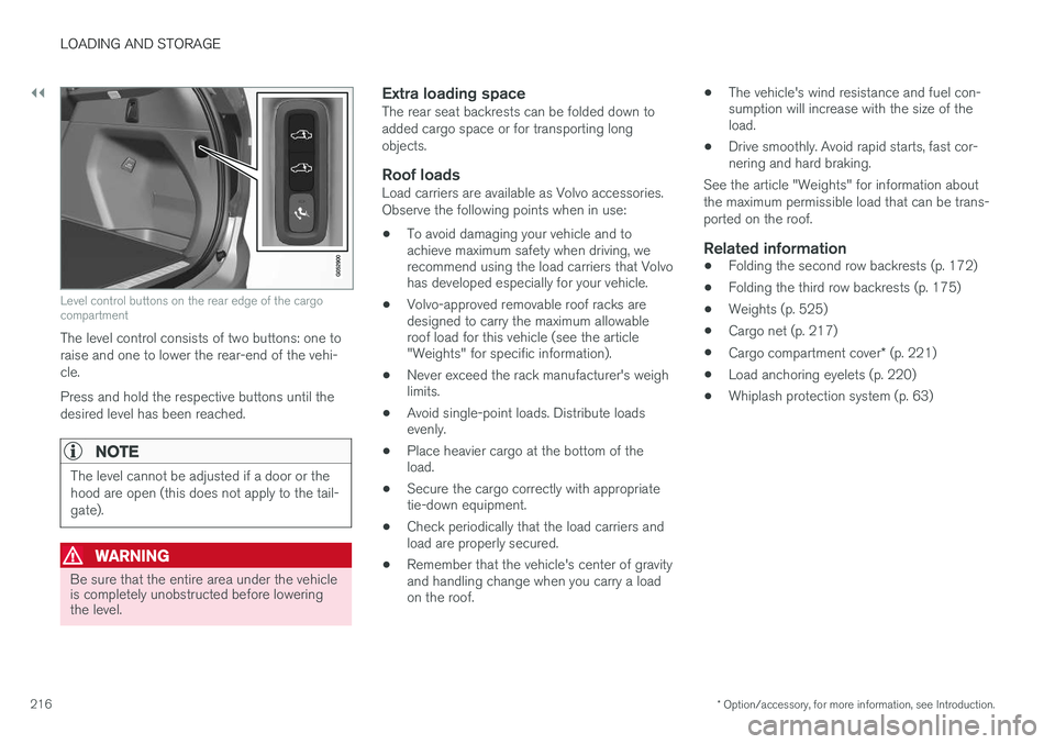
Level control buttons on the rear edge of the cargo compartment
The level control consists of two buttons: one to raise and one to lower the rear-end of the vehi-cle. Press and hold the respective buttons until the desired level has been reached.
NOTE
The level cannot be adjusted if a door or the hood are open (this does not apply to the tail-gate).
WARNING
Be sure that the entire area under the vehicle is completely unobstructed before loweringthe level.
Extra loading spaceThe rear seat backrests can be folded down to added cargo space or for transporting longobjects.
Roof loadsLoad carriers are available as Volvo accessories.Observe the following points when in use:
• To avoid damaging your vehicle and to achieve maximum safety when driving, werecommend using the load carriers that Volvohas developed especially for your vehicle.
• Volvo-approved removable roof racks aredesigned to carry the maximum allowableroof load for this vehicle (see the article"Weights" for specific information).
• Never exceed the rack manufacturer's weighlimits.
• Avoid single-point loads. Distribute loadsevenly.
• Place heavier cargo at the bottom of theload.
• Secure the cargo correctly with appropriatetie-down equipment.
• Check periodically that the load carriers andload are properly secured.
• Remember that the vehicle's center of gravityand handling change when you carry a loadon the roof. •
The vehicle's wind resistance and fuel con-sumption will increase with the size of theload.
• Drive smoothly. Avoid rapid starts, fast cor-nering and hard braking.
See the article "Weights" for information about the maximum permissible load that can be trans-ported on the roof.
Related information
• Folding the second row backrests (p. 172)
• Folding the third row backrests (p. 175)
• Weights (p. 525)
• Cargo net (p. 217)
• Cargo compartment cover
* (p. 221)
• Load anchoring eyelets (p. 220)
• Whiplash protection system (p. 63)
Page 323 of 546

DRIVER SUPPORT
* Option/accessory, for more information, see Introduction.321
Points to keep in mindPAP is a parking aid only and the driver should always be prepared to take control and cancel aparking sequence. This can be due to one ormore of the following factors:
• PAP's function is based on the way that the vehicles are parked behind and in front ofyour parking space. If they are, for example,parked too close to the curb, there is a riskthat your vehicle's tires or wheel rims couldbe damaged by the curb during the parkingprocedure.
• PAP is intended to provide parking assis-tance on straight streets, not sections ofstreet with curved or irregular curbs. Be surethat your vehicle is parallel to the curb whenPAP measures the parking space.
• PAP may not be able to provide parkingassistance on narrow streets due to lack ofspace to maneuver the vehicle. In situationslike this, it may help to drive between 1.5-5 ft(0.5-1.5 m) from the side of the road wherethe parking space is located.
• Use only approved tires with the correct infla-tion pressure because this affects PAP'scapacity to provide parking assistance.Changing to a different approved tire sizemay affect PAP's parameters. Consult atrained and qualified Volvo service technician.
• Heavy rain or snow may inhibit PAP'scapacity to correctly measure a parkingspace. •
Do not use PAP when using snow chainsand/or a temporary spare tire.
• Do not use PAP if there are any objects pro-truding from the vehicle.
WARNING
• The front end of your vehicle may turn out toward oncoming traffic during the park-ing procedure.
• Objects located above the parking sen-sors' field of vision are not included whenPAP measures a parking space. For thisreason, PAP may turn into the parkingspace too soon. Avoid parking spaces ofthis type.
• The driver is always responsible for deter-mining if PAP has selected a suitableparking space.
Maintenance
Location of the PAP sensors
PAP uses the same sensors as the Park Assist system. To function correctly, these sensors mustbe cleaned regularly with water and a suitable carwashing detergent.
Related information
•
Park Assist Pilot (PAP)
* (p. 316)
• Park Assist Pilot (PAP)
* limitations (p. 320)
• Park Assist Pilot (PAP)
* symbols and mes-
sages (p. 322)
Page 447 of 546

WHEELS AND TIRES
}}
445
to reduce the chance of oversteer during hard braking.
• Hitting curbs or potholes can damage thetires and/or wheels permanently.
Tire rotationYour vehicle has no required tire rotation. Tire wear is affected by a number of factors such astire inflation, ambient temperature, driving style,etc.
NOTE
• If the tires are rotated, they should only be moved from front to rear or vice versa.They should never be rotated left toright/right to left.
• Ideally, tire rotation should be done thefirst time after approximately 3,000 miles(5,000 km) and thereafter at 6,000-mile(10,000-km) intervals. Some customersfind that tire rotation may help to getextra mileage from tire life.
• Tire rotation should only be performed iffront/rear tire wear is fairly even andtread height is above 1/16" (1.6 mm).
Storing wheels and tiresWhen storing complete wheels (tires mounted on rims), they should be suspended off the floor orplaced on their sides on the floor. Tires not mounted on rims should be stored ontheir sides or standing upright, but should not besuspended.
CAUTION
Tires should preferably be stored in a cool, dry, dark place, and should never be stored inclose proximity to solvents, gasoline, oils, etc.
WARNING
•
The wheel and tire sizes for your Volvo are specified to meet stringent stabilityand handling requirements. Unapprovedwheel/tire size combinations can nega-tively affect your vehicle's stability andhandling.
• Any damage caused by installation ofunapproved wheel/tire size combinationswill not be covered by your new vehiclewarranty. Volvo assumes no responsibilityfor death, injury, or expenses that mayresult from such installations.
Related information
•
Checking tire inflation pressure (p. 451)
• Tread wear indicator (p. 449)
Tire sidewall designations
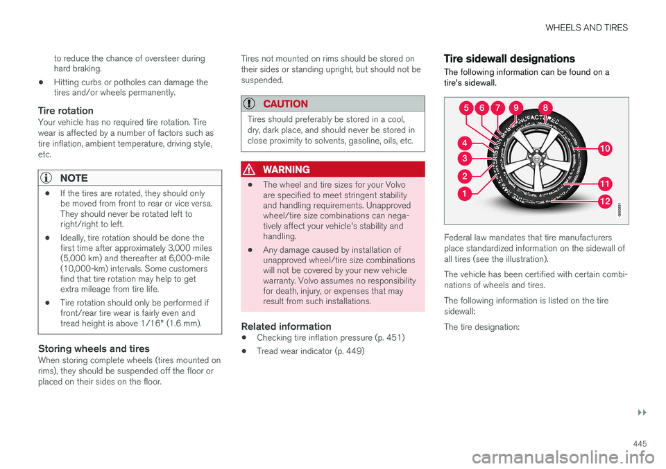
The following information can be found on a tire's sidewall.
Federal law mandates that tire manufacturers place standardized information on the sidewall ofall tires (see the illustration). The vehicle has been certified with certain combi- nations of wheels and tires. The following information is listed on the tire sidewall: The tire designation:
Page 448 of 546

||
WHEELS AND TIRES
446
NOTE
Please be aware that the following tire desig- nation is an example only and that this par-
ticular tire may not be available on your vehi- cle.
1. 215 : the width of the tire (in millimeters)
from sidewall edge to sidewall edge. The larger the number, the wider the tire.
2. 65: The ratio of the tire's height to its width
in percent.
3. R: Radial tire (the designation RF and the
symbol indicate that the vehicle is
equipped with optional self-supporting run flat tires 2
.
4. 15: The diameter of the wheel rim (in
inches).
5. 95: The tire's load index. In this example, a
load index of 95 equals a maximum load of 1521 lbs (690 kg).
6. H: The tire's speed rating, or the maximum
speed at which the tire is designed to bedriven for extended periods of time, carryinga permissible load for the vehicle, and withcorrect inflation pressure. For example, Hindicates a speed rating of 130 mph(210 km/h).
NOTE
The tire's load index and speed rating may not appear on the sidewall because they arenot required by law.
7. M+S or M/S = Mud and Snow, AT = All Ter-
rain, AS = All Season
8. U.S. DOT Tire Identification Number (TIN) : This begins with the letters "DOT" and
indicates that the tire meets all federalstandards. The next two numbers or lettersare the plant code where it was manufac-tured, the next two are the tire size code andthe last four numbers represent the weekand year the tire was built. For example,1510 means that the tire was manufacturedduring week 15 of 2010. The numbers inbetween are marketing codes used at themanufacturer's discretion. This informationhelps a tire manufacturer identify a tire forsafety recall purposes.
9. Tire Ply Composition and MaterialUsed : Indicates the number of plies indi-
cates or the number of layers of rubber-coated fabric in the tire tread and sidewall.Tire manufacturers also must indicate the plymaterials in the tire and the sidewall, whichinclude steel, nylon, polyester, and others. 10.
Maximum Load : Indicates the maximum
load in pounds and kilograms that can becarried by the tire. Refer to the vehicle's tireinformation placard located on the B-Pillarfor the correct tire pressure for your vehicle.
11. Treadwear, Traction, and Temperaturegrades .
12. Maximum permissible inflationpressure: the greatest amount of air pres-
sure that should ever be put in the tire. Thislimit is set by the tire manufacturer.
Speed SymbolA tire's Speed Symbol (SS) indicates the maxi-mum speed for which the tire has been certifiedand should be at least equivalent to the vehicle'stop speed. Winter tires, with our without studs, are excep- tions and may use a lower SS. When winter tiresare installed, the vehicle may not be driven fasterthan the tires' SS. The vehicle's speed should always be determined by the posted speed limit and traffic and roadconditions, not the tire's SS. The following table indicates the maximum per- missible speed for each SS.
2 Self-supporting run flat tires may not be available on all models
Page 449 of 546

WHEELS AND TIRES
}}
447
Speed Symbol
M81 mph (130 km/h)
Q100 mph (160 km/h)
T118 mph (190 km/h)
H130 mph (210 km/h)
V149 mph (240 km/h)
W168 mph (270 km/h)
Y186 mph (300 km/h)
WARNING
•The wheel and tire sizes for your Volvo are specified to meet stringent stabilityand handling requirements. Unapprovedwheel/tire size combinations can nega-tively affect your vehicle's stability andhandling.
• Any damage caused by installation ofunapproved wheel/tire size combinationswill not be covered by your new vehiclewarranty. Volvo assumes no responsibilityfor death, injury, or expenses that mayresult from such installations.
Wheel (rim) designations Wheel and rim dimensions are shown in the fol- lowing table.
The vehicle has been certified with certain combi- nations of wheels and tires. The following table shows an
example of wheel
dimensions: 8Jx18x42.5. This wheel may not be available on your vehicle.
8Wheel width in inches
JRim flange profile
18Wheel diameter in inches
42.5Offset in mm (distance from the center of the wheel to the wheel's contact sur-face on the hub)
Related information
• Tire sidewall designations (p. 445)
Tire terminology The following is a glossary of tire-related terms.
The tire suppliers may have additional markings, notes or warnings such as standard load, radialtubeless, etc.
• Tire information placard
: A placard show-
ing the OE (Original Equipment) tire sizes, recommended inflation pressure, and themaximum weight the vehicle can carry.
• Tire Identification Number (TIN)
: A number
on the sidewall of each tire providing infor-mation about the tire brand and manufactur-ing plant, tire size and date of manufacturer.
• Inflation pressure
: A measure of the
amount of air in a tire.
• Standard load
: A class of P-metric or Metric
tires designed to carry a maximum load at35 psi [37 psi (2.5 bar) for Metric tires].Increasing the inflation pressure beyond thispressure will not increase the tires load car-rying capability.
• Extra load
: A class of P-metric or Metric
tires designed to carry a heavier maximumload at 41 psi [43 psi (2.9 bar) for Metrictires]. Increasing the inflation pressurebeyond this pressure will not increase thetire's load carrying capability.
• kPa
: Kilopascal, a metric unit of air pressure.
• PSI
: Pounds per square inch, a standard unit
of air pressure.
Page 451 of 546

WHEELS AND TIRES
}}
449
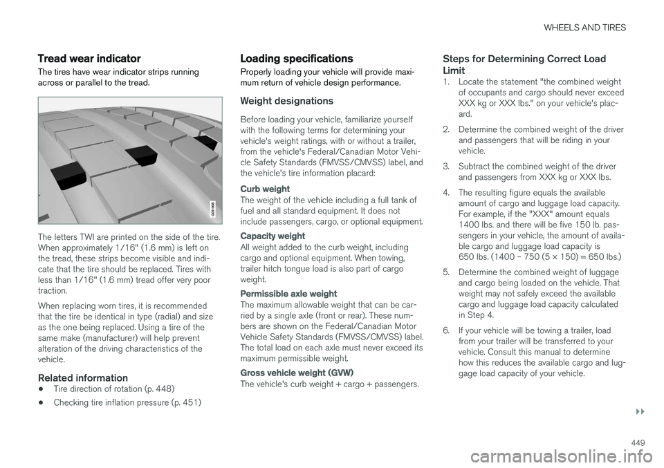
Tread wear indicatorThe tires have wear indicator strips running across or parallel to the tread.
The letters TWI are printed on the side of the tire. When approximately 1/16" (1.6 mm) is left onthe tread, these strips become visible and indi-cate that the tire should be replaced. Tires withless than 1/16" (1.6 mm) tread offer very poortraction. When replacing worn tires, it is recommended that the tire be identical in type (radial) and sizeas the one being replaced. Using a tire of thesame make (manufacturer) will help preventalteration of the driving characteristics of thevehicle.
Related information
• Tire direction of rotation (p. 448)
• Checking tire inflation pressure (p. 451)
Loading specifications Properly loading your vehicle will provide maxi- mum return of vehicle design performance.
Weight designations
Before loading your vehicle, familiarize yourself with the following terms for determining yourvehicle's weight ratings, with or without a trailer,from the vehicle's Federal/Canadian Motor Vehi-cle Safety Standards (FMVSS/CMVSS) label, andthe vehicle's tire information placard:
Curb weight
The weight of the vehicle including a full tank of fuel and all standard equipment. It does notinclude passengers, cargo, or optional equipment.
Capacity weight
All weight added to the curb weight, including cargo and optional equipment. When towing,trailer hitch tongue load is also part of cargoweight.
Permissible axle weight
The maximum allowable weight that can be car- ried by a single axle (front or rear). These num-bers are shown on the Federal/Canadian MotorVehicle Safety Standards (FMVSS/CMVSS) label.The total load on each axle must never exceed itsmaximum permissible weight.
Gross vehicle weight (GVW)
The vehicle's curb weight + cargo + passengers.
Steps for Determining Correct Load Limit
1. Locate the statement "the combined weight
of occupants and cargo should never exceed XXX kg or XXX lbs." on your vehicle's plac-ard.
2. Determine the combined weight of the driver and passengers that will be riding in yourvehicle.
3. Subtract the combined weight of the driver and passengers from XXX kg or XXX lbs.
4. The resulting figure equals the available amount of cargo and luggage load capacity.For example, if the "XXX" amount equals1400 lbs. and there will be five 150 lb. pas-sengers in your vehicle, the amount of availa-ble cargo and luggage load capacity is650 lbs. (1400 – 750 (5 × 150) = 650 lbs.)
5. Determine the combined weight of luggage and cargo being loaded on the vehicle. Thatweight may not safely exceed the availablecargo and luggage load capacity calculatedin Step 4.
6. If your vehicle will be towing a trailer, load from your trailer will be transferred to yourvehicle. Consult this manual to determinehow this reduces the available cargo and lug-gage load capacity of your vehicle.
Page 453 of 546

WHEELS AND TIRES
}}
451
Snow tires and chains
The use of snow chains and/or winter tires can help improve traction in winter driving conditions.
Snow chains can be used on your Volvo with the following restrictions:
• Snow chains should be installed on front wheels only. Use only Volvo approved snowchains.
• If accessory, aftermarket or "custom" tiresand wheels are installed and are of a size dif-ferent than the original tires and wheels,chains in some cases CANNOT be used.Sufficient clearances between chains andbrakes, suspension and body componentsmust be maintained.
• Some strap-on type chains will interfere withbrake components and therefore CANNOTbe used.
• All Wheel Drive models
: Snow chains
should only be installed on the front wheels.
• Certain size tires may not allow the assemblyof snow chains/traction devices.
Consult your Volvo retailer for additional snow chain information.
CAUTION
• Snow chains should not be used on wheels larger than 19".
• Always follow the chain manufacturer'sinstallation instructions carefully. Installchains as tightly as possible andretighten periodically.
• Check local regulations regarding the useof snow chains before installing.
• Use single-sided snow chains only.
• Never exceed the chain manufacturer'sspecified maximum speed limit. (Underno circumstances should you exceed31 mph (50 km/h).
• Avoid bumps, holes or sharp turns whendriving with snow chains.
• The handling of the vehicle can beadversely affected when driving withchains. Avoid fast or sharp turns as wellas locked wheel braking.
Checking tire inflation pressure
Correct tire inflation pressure helps improve driv- ing stability, save fuel and increase the servicelife of the tires.
WARNING
• Under-inflation is the most common cause of tire failure and may result insevere tire cracking, tread separation, or"blow-out," with unexpected loss of vehi-cle control and increased risk of injury.
• Under-inflated tires reduce the load car-rying capacity of your vehicle.
Cold tiresInflation pressure should be checked when the tires are cold. The tires are considered to be cold when they have the same temperature as the sur-rounding (ambient) air. This temperature is normally reached after the vehicle has been parked for at least 3 hours. After driving a distance of approximately 1 mile (1.6 km), the tires are considered to be hot. If youhave to drive farther than this distance to pumpyour tire(s), check and record the tire pressurefirst and add the appropriate air pressure whenyou get to the pump. When weather temperature changes occur, tire inflation pressures also change. A 10-degree