2016 VOLVO V60 CROSS COUNTRY horn
[x] Cancel search: hornPage 67 of 402

03 Instruments and controls
03
* Option/accessory, for more information, see Introduction.65
FunctionSee
Controls for menus and messages, turnsignals, high/lowbeams, trip computer(p. 74), (p. 93),(p. 87),(p. 113)
Paddles for manually shifting gears*(p. 259)
Cruise control(p. 176)
Horn, airbag(p. 85), (p. 33)
Main instrument panel(p. 66)
Infotainment system/ Bluetooth hands-freecontrolsSensus Info- tainmentsupplement
START/STOP ENGINE button(p. 76)
Ignition slot(p. 76)
Display for infotain- ment system func-tions and menus(p. 111), Sensus Info-tainmentsupplement
Door handle-
FunctionSee
In-door control pan- els (power windows,mirrors, central lock-ing button)(p. 99), (p. 100),(p. 160)
Hazard warning flashers(p. 93)
Controls for the info- tainment system andmenus(p. 74), (p. 126),Sensus Info-tainmentsupplement
Climate system con- trols(p. 126)
Gear selector(p. 257)
Controls for active chassis (Four-C)*(p. 169)
Wipers and washers(p. 96), (p. 97)
Steering wheel adjustment(p. 85)
Hood opening control(p. 332)
Parking brake(p. 274)
FunctionSee
Power seat* adjust- ment controls(p. 79)
Lighting panel, but- tons for opening fuelfiller door andunlocking the tailgate(p. 87), (p. 283),(p. 162)
Related information
• Information displays – ambient tempera- ture sensor (p. 75)
• Information displays – trip odometer andclock (p. 76)
Page 87 of 402

03 Instruments and controls
03
}}
* Option/accessory, for more information, see Introduction.85
NOTE
It may be necessary to move the front seats forward or put their backrests in amore upright position before folding downthe rear seat backrests.
WARNING
• When one or more sections of the backrest is returned to the uprightposition, check that it is properlylocked in place by pushing and pullingit. The red indicators should also notbe visible.
• Return the outboard head restraints tothe upright position.
• Long loads should always be securelyanchored to help avoid injury in theevent of a sudden stop.
• Always turn the engine off and applythe parking brake when loading/unloading the vehicle.
• Place the transmission in the Park (
P)
position to help prevent inadvertentmovement of the gear selector.
• On hot days, the temperature in thevehicle interior can rise very quickly.Exposure of people to these high tem-peratures for even a short period oftime can cause heat-related injury ordeath. Small children are particularly atrisk.
Related information
•
Front seats (p. 78)
• Front seats – power seat (p. 79)
• Rear seats – head restraints (p. 82)
Steering wheel
The steering wheel can be adjusted to various positions and has controls for the horn, cruisecontrol*, menus, the infotainment system and Bluetooth
®-connected cell phone.
Adjusting
G021138
Adjusting the steering wheel
Lever for releasing/locking the steering wheel
Possible positions
To adjust the steering wheel's height and reach:
1. Pull the lever toward you to release the steering wheel.
2. Adjust the steering wheel to the position that suits you.
Page 88 of 402

||
03 Instruments and controls
03
86* Option/accessory, for more information, see Introduction.
3. Push back the lever to lock the steering
wheel in place. If the lever is difficult to push into place, press the steering wheellightly at the same time as you push thelever.
WARNING
Never adjust the steering wheel while driv- ing.
With the optional speed-dependent power steering the level of steering force can beadjusted, see Active chassis* (Four C)(p. 169).
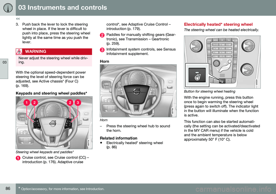
Keypads and steering wheel paddles*
Steering wheel keypads and paddles*
Cruise control, see Cruise control (CC) – introduction (p. 176). Adaptive cruise control*, see Adaptive Cruise Control –introduction (p. 179).
Paddles for manually shifting gears (Gear- tronic), see Transmission – Geartronic(p. 259).
Infotainment system controls, see Sensus Infotainment supplement.
Horn
Horn
–Press the steering wheel hub to sound the horn.
Related information
•
Electrically heated* steering wheel (p. 86)
Electrically heated* steering wheel
The steering wheel can be heated electrically.
Button for steering wheel heating
With the engine running, press this button once to begin warming the steering wheel(press again to switch off). The indicator lightin the button will illuminate when the functionis active. This function can also be started automati- cally (the setting can be activated/deactivatedin the MY CAR menu) if the vehicle is coldand the ambient temperature is belowapproximately 50° F (10° C).
Page 152 of 402

||
06 Locks and alarm
06
150* Option/accessory, for more information, see Introduction.
After a short pause, press the Unlock button a second time within 10 seconds to unlockthe other doors and the tailgate. This function can be changed so that all doors unlock at the same time by pressing My Car and going to
SettingsCar
settings
Lock settingsChange doors
unlock setting. For a description of the menu
system, see My Car – introduction (p. 74).
Approach lighting – As you approach
the vehicle, press the button on the remote key to light the interior lighting, parking lights,license plate lighting and the lights in the doormirrors*. These lights will switch off automatically after 30, 60 or 90 seconds. For a description of themenu system, see My Car – introduction(p. 74).
Unlock tailgate – Press the button twice
within several seconds to disarm the alarm system (the alarm indicator light on the dash-board will go out), and unlock only the tail-gate.
NOTE
As an added safety precaution, the parking lights will come on automatically for ashort period when the tailgate has beenopened.
After closing, the tailgate will not automati- cally relock. Press Lock to relock it and rearmthe alarm. For information on opening the tailgate from the passenger compartment, see Locking/unlocking – tailgate (p. 162)
Panic alarm – This button can be used
to attract attention during emergency situa- tions. To activate the panic alarm, press and hold this button for at least 3 seconds or press ittwice within 3 seconds. The turn signals andhorn will be activated. The panic alarm willstop automatically after 2 minutes and45 seconds. To deactivate, wait approximately 5 seconds and press the button again. The Panic alarm button will not unlock the vehicle.
Related information
• Locking/unlocking – from inside (p. 160)
• Locking/unlocking – from the outside (p. 159)
• Locking/unlocking confirmation (p. 147)
Remote key – range
The remote key has a range of approximately 60 ft. (20 m) from the vehicle.
NOTE
Buildings or other obstacles may interfere with the function of the remote key. Thevehicle can also be locked or unlockedwith the key blade, see Alarm-related func-tions (p. 166).
If the remote key is removed from the vehicle while the engine is running or if the ignition isin mode
I or II and all of the doors are closed,
a message will appear in the instrument paneldisplay and there will be an audible signal. When the remote key is returned to the vehi- cle, the message will be erased and the audi-ble signal will stop after one of the followinghas been done: • The remote key is inserted in the ignition slot
• The vehicle's speed exceeds 20 mph(30 km/h)
• The
OK button on the left steering wheel
lever is pressed
Related information
• Remote key – functions (p. 149)
Page 241 of 402

07 Driver support
07
}}
* Option/accessory, for more information, see Introduction.239
Park Assist Pilot (PAP)* – limitations
The PAP parking procedure will be cancelled if.
• The vehicle's speed goes above approxi- mately 4 mph 7 km/h
• The driver moves the steering wheel
• If the stability or ABS systems are acti-vated (e.g., if a wheel starts to spinbecause of a slippery road surface
If the system has been switched off, this will be indicated by a text message in the instru-ment panel.
NOTE
• PAP will not function correctly if its sensors are obstructed by dirt, snow,etc.
• In certain situations, PAP may not beable to measure a parking space. Thiscould be due to external sources ofsound (e.g., a vehicle's horn, tires onwet asphalt, pneumatic brakes, noisefrom a motorcycle's exhaust, etc.)emitting ultrasound using approxi-mately the same frequencies as PAP.
Information to keep in mindPAP is only intended to provide parallel park- ing assistance but may not be able to func-tion fully in all situations. •
PAP's function is based on the way that the vehicles are parked behind and infront of your parking space. If they are,for example, parked too close to the curb,there is a risk that your vehicle's tires orwheel rims could be damaged by thecurb during the parking procedure.
• PAP is intended to provide parking assis-tance on straight streets, not sections ofstreet with curved or irregular curbs. Besure that your vehicle is parallel to thecurb when PAP measures the parkingspace.
• PAP may not be able to provide parkingassistance on narrow streets due to lackof space to maneuver the vehicle. In sit-uations like this, it may help to drive asclose to the side of the road as possiblewhere the parking space is located.
• Use only approved tires with the correctinflation pressure because this affectsPAP's capacity to provide parking assis-tance. See the table in Tire inflation –pressure table (p. 305). Changing to adifferent approved tire size may affectPAP's parameters. Consult a trained andqualified Volvo service technician.
• Heavy rain or snow may inhibit PAP'scapacity to correctly measure a parkingspace.
• Do not use PAP if snow chains or a tem-porary spare tire is being used.
• Do not use PAP if there are any objectsprotruding from the vehicle.
WARNING
• The front end of your vehicle may turn out toward oncoming traffic during theparking procedure.
• Objects located above the parkingsensors' field of vision are not includedwhen PAP measures a parking space.For this reason, PAP may turn into theparking space too soon. Avoid parkingspaces of this type.
• The driver is always responsible fordetermining if PAP has selected a suit-able parking space.
Maintenance
Generic illustration. The PAP sensors are located in the front and rear bumpers
PAP uses the same sensors as the Park assist system, see Park assist – limitations(p. 235)).
Page 242 of 402

||
07 Driver support
07
240* Option/accessory, for more information, see Introduction.
The sensors must be cleaned regularly to ensure that they work properly. Clean themwith water and a suitable car washing deter-gent.
Related information
• Park Assist Pilot (PAP)* – introduction (p. 236)
• Park Assist Pilot (PAP)* – function (p. 236)
• Park Assist Pilot (PAP)* – operation(p. 237)
• Park Assist Pilot (PAP)* – symbols andmessages (p. 240)
• Park assist – introduction (p. 232)
• Rear Park Assist Camera (PAC) – intro-duction (p. 241)
Park Assist Pilot (PAP)* – symbols and messages
Various PAP-related combinations of sym- bols, graphics and text messages are dis-played in the instrument panel and some-times also include suitable actions. A text message can be erased by pressing briefly on the
OK button on the turn signal
lever. Contact a Volvo retailer or a trained and qualified Volvo service technician If a mes-sage indicating that PAP is not functioningproperly is displayed.
Related information
• Park Assist Pilot (PAP)* – introduction (p. 236)
• Park Assist Pilot (PAP)* – function (p. 236)
• Park Assist Pilot (PAP)* – operation(p. 237)
• Park Assist Pilot (PAP)* – limitations(p. 239)
• Park assist – introduction (p. 232)
• Rear Park Assist Camera (PAC) – intro-duction (p. 241)
Park assist – troubleshooting
Faults in the systemIf the information symbol illuminates andPark assist syst Service required is shown
on the information display, this indicates that the system is not functioning properly andhas been disengaged. Consult a trained andqualified Volvo service technician.
CAUTION
In certain circumstances, the park assist system may give unexpected warning sig-nals that can be caused by external soundsources that use the same ultrasound fre-quencies as the system. This may includesuch things as the horns of other vehicles,wet tires on asphalt, pneumatic brakes,motorcycle exhaust pipes, etc. This doesnot indicate a fault in the system.
Related information
• Park assist – introduction (p. 232)
• Park assist – limitations (p. 235)
• Park assist – function (p. 232)
• Park assist – operation (p. 234)
• Rear Park Assist Camera (PAC) – function (p. 241)
Page 359 of 402

10 Maintenance and servicing
10
* Option/accessory, for more information, see Introduction.357
PosFunctionA
Auxiliary lights*20
Horn15
Relay coils, Engine Control Module (ECM)10
Control module - auto- matic transmission15
A/C compressor (not 4-cyl. engines)15
Relay-coils A/C, relay coils in engine com-partment cold zone forStart/Stop5
Starter motor relay A30
Engine control module (4-cyl. engines) Ignition coils (5-cyl. engine)20
Engine Control Module (4-cyl. engines)20
Engine Control Module (5-cyl. engine)10
PosFunctionA
4-cyl. engines: mass air meter, thermostat,EVAP valve10
5-cyl. engine: Injection system, engine controlmodule15
A/C compressor (5-cyl. engine), engine valves,oil level sensor (5-cyl.only)10
Engine valves/oil pump/center heatedoxygen sensor (4-cyl.engines)15
Front/rear heated oxy- gen sensors (4-cyl.engines), EVAP valve(5-cyl. engine), heatedoxygen sensors (5-cyl.engine)15
Oil pump/crankcase ventilation heater/cool-ant pump (5-cyl.engines)10
Ignition coils (4-cyl. engines)15
PosFunctionA
Fuel leakage detection (5-cyl. engine), controlmodule for radiatorshutter (5-cyl. engine)5
Fuel leakage detection, A/C solenoid (4-cyl.engines)7.5
Coolant pump (4-cyl. engines)50
Cooling fan60 (4/5- cyl.engines)
80 (6-cyl. engines)
Power steering100
A
This position is not used on vehicles with the optional Start/Stop function, refer to the table "Engine compart-ment cold zone" in Fuses – engine compartment cold zone(Start/Stop only) (p. 362).
Related information
• Fuses – glove compartment (p. 358)
• Fuses – cargo area/trunk (p. 361)
Page 395 of 402

12 Index
12
393
High beams................................................ 88
active.................................................... 88
Hill Descent Control......................... 269, 270
Hill Start Assist (HSA).............................. 257
Hoisting the vehicle................................. 329 HomeLink ®
Wireless Control
System............................................. 106, 107
Home safe lighting..................................... 95
Hood, opening/closing............................ 332
Horn........................................................... 86
I
ID, Volvo.................................................... 21
Ignition modes..................................... 76, 77
Immobilizer.............................................. 148
Important information.......................... 13, 14
Indicator lights............................... 66, 68, 72
Infant seats................................................ 49
Inflatable Curtain........................................ 41
Inflation pressure............................. 301, 302
Inflation pressure table............................ 305Information and warning symbols, table
of.............................................................. 385
Information lights........................... 66, 68, 72 Inspection readiness................................ 330
Instrument lighting..................................... 91
"theater" lighting................................... 91
Instrument overview............................ 63, 66
Instrument panel........................ 66, 111, 112Integrated two-stage booster
cushion.......................................... 57, 59, 60
Interior Air Quality System....................... 123
Interior lighting........................................... 94Internet connection booking service.................................. 330
ISOFIX/LATCH anchors............................. 55J
Jack attaching............................................. 296
location of........................................... 296
Jump starting........................................... 256
K
Key blade. 146, 147, 150, 151, 152, 153, 156 private locking.................................... 152
Keyless drive............................................ 155 general description............. 156, 157, 158
starting the vehicle............................. 252
Keyless locking/unlocking....................... 155
L
Labels list of................................................... 373
location of........................................... 372
Lane Departure Warning (LDW) 222, 223, 224, 225
Lane Keeping Aid............ 227, 228, 230, 231
LATCH anchors......................................... 55
Leather care............................................. 366
Lighting panel............................................ 87
Loading the vehicle.................. 139, 140, 306 roof loads............................................ 139
Locking.................................... 159, 160, 162 tailgate................................................ 162
Locking the vehicle.................................. 149
Locks, child safety..................................... 61