2016 VOLVO V60 CROSS COUNTRY tow
[x] Cancel search: towPage 97 of 402
03 Instruments and controls
03
95
Related information
•Rear interior lighting (p. 95)
Rear interior lighting
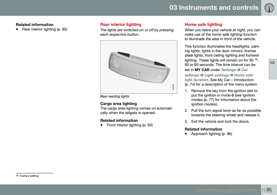
The lights are switched on or off by pressing each respective button.
G021150
Rear reading lights
Cargo area lightingThe cargo area lighting comes on automati- cally when the tailgate is opened.
Related information
•Front interior lighting (p. 94)
Home safe lighting
When you leave your vehicle at night, you can make use of the home safe lighting functionto illuminate the area in front of the vehicle. This function illuminates the headlights, park- ing lights, lights in the door mirrors, licenseplate lights, front ceiling lighting and footwell lighting. These lights will remain on for 30 19
,
60 or 90 seconds. The time interval can be set in MY CAR under
SettingsCar
settings
Light settingsHome safe
light duration. See My Car – introduction
(p. 74) for a description of the menu system.
1. Remove the key from the ignition slot to put the ignition in mode 0 (see Ignition
modes (p. 77) for information about the ignition modes).
2. Pull the turn signal lever as far as possible towards the steering wheel and release it.
3. Exit the vehicle and lock the doors.
Related information
• Approach lighting (p. 96)
19
Factory setting
Page 98 of 402

03 Instruments and controls
03
96* Option/accessory, for more information, see Introduction.
Approach lighting
Approach lighting activates the parking lights, door mirror lights, license plate lighting, domelighting and door step lighting when youapproach the vehicle. This function is activated by pressing the approach light button on the remote key (see
the illustration in Remote key – functions(p. 149)). The time interval for this lighting can be set by pressing MY CAR and going to
Car
settings
Light settingsApproach light
duration. See My Car – introduction (p. 74)
for a description of the menu system.
Related information
• Home safe lighting (p. 95)
Windshield wipers
Move the lever toward the steering wheel to start the windshield and headlight washers.After the lever is released the wipers makeseveral extra sweeps.
Windshield wipers and washers
Rain sensor* on/off
Thumb wheel sensitivity/frequency
CAUTION
•Use ample washer fluid when washing the windshield. The windshield shouldbe thoroughly wet when the wipers arein operation.
• Before using the wipers, ice and snowshould be removed from the wind-shield/rear window. Be sure the wiperblades are not frozen in place.
Windshield wipers offMove the lever to position
0 to
switch off the windshield wipers.
Single sweepMove the lever upward from posi- tion 0 to sweep the windshield one
stroke at a time for as long as the
lever is held up.
Intermittent wipingWith the lever in this position, you can set the wiper interval by twistingthe thumb wheel upward to increase
wiper speed or downward to decrease thespeed.
Continuous wipingThe wipers operate at normal speed.
The wipers operate at high speed.
Windshield wiper service positionThe windshield wipers must be in the service position before the wiper blades can becleaned or replaced. See Wiper blades –service position (p. 347) for additional infor-mation.
Related information
• Engine compartment – washer fluid (p. 349)
Page 99 of 402

03 Instruments and controls
03
}}
* Option/accessory, for more information, see Introduction.97
Rain sensor*
The rain sensor automatically regulates wiper speed according to the amount of water onthe windshield. The sensitivity of the rain sensor can be adjusted moving the thumb wheel up (thewipers will sweep the windshield more fre-quently) or down (the wipers will sweep thewindshield less frequently).
NOTE
The wipers will make an extra sweep each time the thumb wheel is adjusted upward.
When the rain sensor is activated, the symbol
will illuminate in the instrument panel.
Activating and setting the sensitivityWhen activating the rain sensor, the vehicle must be running or in ignition mode II and the
windshield wiper lever must be in position 0
or in the single sweep position. Activate the rain sensor by pressing the but- ton
. The windshield wipers will make
one sweep. Press the lever up for the wipers to make an extra sweep. The rain sensor returns to activemode when the stalk is released back toposition 0.
DeactivatingDeactivate the rain sensor by pressing the button
or press the lever down to
another wiper position. The rain sensor is automatically deactivated when the key is removed from the ignitionslot or five minutes after the ignition has beenswitched off.
CAUTION
The rain sensor should be deactivated when washing the car in an automatic carwash, etc. If the rain sensor function is lefton, the wipers will start inadvertently in thecar wash and could be damaged.
Windshield washer
Move the lever toward the steering wheel to start the windshield and headlight washers.After the lever is released the wipers makeseveral extra sweeps.
Washing function
Heated washer nozzles*The washer nozzles are heated automatically in cold weather to help prevent the washerfluid from freezing.
High-pressure headlight washing*High-pressure headlight washing consumes alarge quantity of washer fluid. To save fluid,the headlights are washed using two alterna-tives:
• Low/high beam headlights on.
The
headlights will be washed the first time the windshield is washed. Thereafter, theheadlights will only be washed once for
Page 127 of 402
04 Climate
04
* Option/accessory, for more information, see Introduction.125
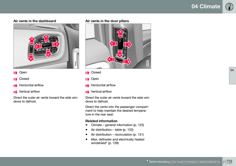
Air vents in the dashboard
Open
Closed
Horizontal airflow
Vertical airflow
Direct the outer air vents toward the side win- dows to defrost.
Air vents in the door pillars
Closed
Open
Horizontal airflow
Vertical airflow
Direct the outer air vents toward the side win- dows to defrost. Direct the vents into the passenger compart- ment to help maintain the desired tempera-ture in the rear seat.
Related information
• Climate – general information (p. 122)
• Air distribution – table (p. 132)
• Air distribution – recirculation (p. 131)
• Max. defroster and electrically heated windshield* (p. 129)
Page 145 of 402
05 Loading and storage
05
}}
143
Cargo area cover
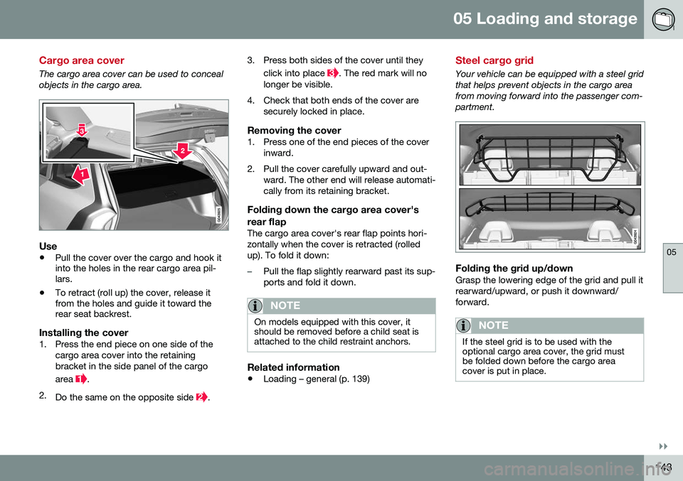
The cargo area cover can be used to conceal objects in the cargo area.
Use
•Pull the cover over the cargo and hook it into the holes in the rear cargo area pil-lars.
• To retract (roll up) the cover, release itfrom the holes and guide it toward therear seat backrest.
Installing the cover1. Press the end piece on one side of the
cargo area cover into the retaining bracket in the side panel of the cargo area
.
2. Do the same on the opposite side
. 3. Press both sides of the cover until they
click into place
. The red mark will no
longer be visible.
4. Check that both ends of the cover are securely locked in place.
Removing the cover1. Press one of the end pieces of the coverinward.
2. Pull the cover carefully upward and out- ward. The other end will release automati- cally from its retaining bracket.
Folding down the cargo area cover's rear flap
The cargo area cover's rear flap points hori- zontally when the cover is retracted (rolledup). To fold it down:
–Pull the flap slightly rearward past its sup- ports and fold it down.
NOTE
On models equipped with this cover, it should be removed before a child seat isattached to the child restraint anchors.
Related information
• Loading – general (p. 139)
Steel cargo grid
Your vehicle can be equipped with a steel grid that helps prevent objects in the cargo areafrom moving forward into the passenger com-partment.
Folding the grid up/downGrasp the lowering edge of the grid and pull it rearward/upward, or push it downward/forward.
NOTE
If the steel grid is to be used with the optional cargo area cover, the grid mustbe folded down before the cargo areacover is put in place.
Page 148 of 402
06 Locks and alarm
06
146
Remote key and key blade
Two remote keys are provided with your vehi- cle. They enable you to unlock the doors andtailgate, and also function as ignition keys tostart the vehicle or operate electrical compo-nents. The remote keys contain detachablemetal key blades for manually locking orunlocking the driver's door and the glovecompartment. The visible ends of these keyblades are unique to make it easier to identify"your" remote key. Up to six remotes can beprogrammed for use on the same vehicle.
WARNING
Never leave the remote key in the ignition slot if children are to remain in the vehicle.
For more information on the various ignition modes, see Ignition modes (p. 77).
Related information
•Remote key – functions (p. 149)
• Remote key – functions (p. 149)
• Remote key – range (p. 150)
Remote key – loss
If either of the remote keys (p. 146) is lost, the other should be taken with the vehicle to aVolvo retailer. As an anti-theft measure, thecode of the lost remote key must be erasedfrom the system.
NOTE
Additional or duplicate remote control keys can be obtained from any authorized Volvoretailer. You can also obtain additional or duplicate remote control keys from certain inde-pendent repair facilities and locksmithsthat are qualified to make remote controlkeys. Each key must be programmed towork with your vehicle. California Only: A list of independent repair facilities and/or locksmiths known to Volvo that can cutand code replacement keys can be found:
• on the Volvo website at http://www.volvocars.com/us/keys
• by calling Volvo Customer Care at1-800-458-1552
The number of registered keys for the vehicle can be found by pressing
MY CAR and going
into
SettingsInformationNumber of
keys. For a description of the menu system,
see My Car – introduction (p. 74). USA-5WK49264 FCC ID:KR55WK49264 + Siemens VDO 5WK49236 FCC ID:KR55WK49236, 5WK49266FCC ID:KR55WK49266 + Siemens VDO 5WK49233 FCC ID:KR55WK49233This device complies with part 15 of the FCC rules and RSS-210. Operation is subject tothe following conditions: (1) This device maynot cause harmful interference, and (2) thisdevice must accept any interferencereceived, including interference that maycause undesired operation. Canada-5WK49264IC:267T-5WK49264 + Siemens VDO 5WK49236 IC:267T-5WK49236, 5WK49266IC:267T-5WK49266 + Siemens VDO 5WK49233 IC:267T-5WK49233Operation is subject to the following condi- tions: (1) this device may not cause interfer-ence, and (2) this device must accept anyinterference, including interference that maycause undesired operation of the device.Related information
•
Remote key – functions (p. 149)
Page 172 of 402
||
07 Driver support
07
170
Spin Control (SC)The SC function is designed to help prevent the drive wheels from spinning while the vehi-cle is accelerating.
Active Yaw Control (AYC)This function helps maintain directional stabil- ity, for example when cornering, by brakingone or more of the wheels if the vehicleshows a tendency to skid or slide laterally.
Corner Traction Control (CTC)CTC compensates for understeering and helps provide additional stability when accel-erating through a curve by preventing theinside wheel from spinning. This is particularlyuseful when accelerating on a curving high-way on-ramp. CTC is most effective if the stability system's Sport mode is selected. See the section
about Sport mode.
Engine Drag Control (EDC)EDC helps keep the engine running if the wheels show a tendency to lock, e.g., whenshifting down in the Geartronic manual shift-ing mode or while using the engine's brakingfunction on a slippery surface. If the enginewere to stop, power steering would not func-tion, making the vehicle more difficult tosteer.
Trailer Stability Assist (TSA)The TSA helps stabilize a vehicle that is tow- ing a trailer when the vehicle and trailer have begun to sway. See Trailer Stability Assist(TSA) (p. 288) for more information. This system is automatically deactivated if the driver selects
Sport mode.
Related information
•Stability system – operation (p. 170)
• Stability system – symbols and messages (p. 172)
• Trailer Stability Assist (TSA) (p. 288)
Stability system – operation
Operation
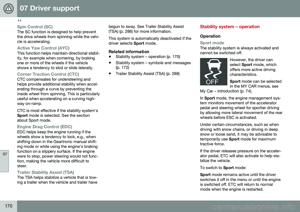
Sport modeThe stability system is always activated and cannot be switched off.
However, the driver canselect Sport mode, which
offers more active drivingcharacteristics. Sport mode can be selected
in the MY CAR menus, see
My Car – introduction (p. 74).
In Sport mode, the engine management sys-
tem monitors movement of the accelerator pedal and steering wheel for sportier drivingby allowing more lateral movement of the rearwheels before ESC is activated. Under certain circumstances, such as when driving with snow chains, or driving in deepsnow or loose sand, it may be advisable totemporarily use Sport mode for maximum
tractive force. If the driver releases pressure on the acceler- ator pedal, ETC will also activate to help sta-bilize the vehicle. To switch to Sport mode:
Sport mode remains active until the driver
switches it off in the menu or until the engine is switched off. ETC will return to normalmode when the engine is restarted.
Page 177 of 402
07 Driver support
07
* Option/accessory, for more information, see Introduction.175
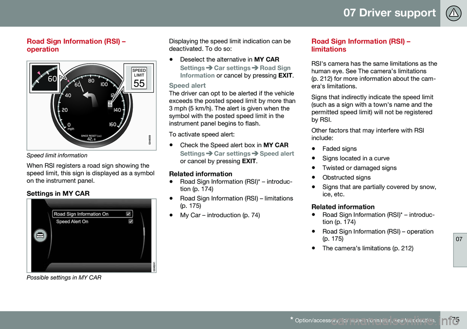
Road Sign Information (RSI) – operation
Speed limit information
When RSI registers a road sign showing the speed limit, this sign is displayed as a symbolon the instrument panel.
Settings in MY CAR
Possible settings in MY CAR Displaying the speed limit indication can be deactivated. To do so:
• Deselect the alternative in
MY CAR
SettingsCar settingsRoad Sign
Information or cancel by pressing EXIT.
Speed alertThe driver can opt to be alerted if the vehicle exceeds the posted speed limit by more than3 mph (5 km/h). The alert is given when thesymbol with the posted speed limit in theinstrument panel begins to flash. To activate speed alert:
• Check the Speed alert box in
MY CAR
SettingsCar settingsSpeed alertor cancel by pressing EXIT.
Related information
•Road Sign Information (RSI)* – introduc- tion (p. 174)
• Road Sign Information (RSI) – limitations(p. 175)
• My Car – introduction (p. 74)
Road Sign Information (RSI) – limitations
RSI's camera has the same limitations as the human eye. See The camera’s limitations(p. 212) for more information about the cam-era's limitations. Signs that indirectly indicate the speed limit (such as a sign with a town's name and thepermitted speed limit) will not be registeredby RSI. Other factors that may interfere with RSI include:
• Faded signs
• Signs located in a curve
• Twisted or damaged signs
• Obstructed signs
• Signs that are partially covered by snow, ice, etc.
Related information
•Road Sign Information (RSI)* – introduc-tion (p. 174)
• Road Sign Information (RSI) – operation(p. 175)
• The camera’s limitations (p. 212)