2016 VOLVO V60 CROSS COUNTRY fog light
[x] Cancel search: fog lightPage 201 of 402

07 Driver support
07
}}
199
City Safety – operation
Using City Safety™
NOTE
The City Safety™ function is activated automatically each time the engine hasbeen switched off and restarted.
On and OffIn certain situations, it may be desirable to switch City Safety™ off, such as when drivingin close quarters where leaves, branches, etc.may obscure the hood and windshield. When the engine is running, City Safety™ can be switched off as follows: Press My Car in the center console control
panel and go to
SettingsCar settings
Driver support systemsCity Safety.
Select
Off.
If the engine is switched off, City Safety™ will reactivate when the engine is restarted.
WARNING
The laser sensor emits light when the igni- tion is in mode II or higher, even if City
Safety™ has been switched off.
To switch City Safety™ on again:
• Follow the same procedure as for switch- ing City Safety™ off but select
On.
Related information
•City Safety – introduction (p. 197)
• City Safety – function (p. 198)
• City Safety – limitations (p. 199)
• City Safety – troubleshooting (p. 200)
• City Safety – symbols and messages (p. 202)
• City Safety – Laser sensor (p. 203)
• My Car – introduction (p. 74)
City Safety – limitations
Limitations
WARNING
The laser sensor has certain limitations and its function may be reduced (or it maynot function at all) in conditions such asheavy rain or snowfall, or by dense fog orthick, blowing dust or snow. Condensa-tion, dirt, ice or snow on the windshieldmay also interfere with the sensor’s func-tion.
The sensor used by City Safety™ is designed to detect cars and other larger motor vehiclesahead of your vehicle in both daylight anddarkness. Objects such as warning flags hanging from long objects on the roof or accessories suchas auxiliary lights or protective arches on thefront of the vehicle that are higher than thehood may also impede the sensor’s function. Braking distance to the vehicle ahead increa- ses on slippery road surfaces, which mayreduce City Safety’s capacity to avoid a colli-sion. In situations like this, the stability sys-tem (see Stability system – introduction(p. 169)) will help provide the best possiblebraking capacity and stability. City Safety™ emits a laser beam and meas- ures the way in which the light is reflected.
Page 214 of 402

07 Driver support
07
212* Option/accessory, for more information, see Introduction.
The camera’s limitations
The camera has the same limitations as the human eye. The camera is used by Pedestrian and Cyclist Detection with Full Auto Brake Collision warn-ing – introduction (p. 204), Active High Beams(Active high beams (AHB)* (p. 88)), Road SignInformation (Road Sign Information (RSI)* –introduction (p. 174)) and Driver Alert System(Driver Alert System (p. 217)) with LaneDeparture Warning or Lane Keeping Aid.
NOTE
• To help protect the camera in very hot conditions, it may be temporarilyswitched off for approximately 15minutes after the engine has beenstarted.
• Keep the section of the windshield infront of the camera clean and free ofice, snow, or condensation.
WARNING
•
The camera has the same type of limi- tations as the human eye, i.e., it can-not see as well in heavy snowfall orrain, thick fog or in heavy blowing dustor snow. In such conditions, systemsdepending on the camera may experi-ence greatly reduced functionality ormay be temporarily deactivated.
• Never place any objects, decals, etc.,on the windshield in front of the cam-era. This could reduce or block thecamera’s function, and could causeone or more of the systems that utilizethe camera to stop functioning.
• Strong sunlight, reflections from theroad surface, ice or snow covering theroad, a dirty road surface, or unclearlane marker lines may drasticallyreduce the camera’s capacity todetect the side of a lane, a pedestrian,a cyclist or another vehicle.
Related information
•
Collision warning – introduction (p. 204)
• Collision warning* – function (p. 206)
• Collision warning* – operation (p. 207)
• Collision warning* – Pedestrian detection (p. 209)
• Collision warning* – Cyclist detection(p. 208)
• Collision warning* – limitations (p. 210) •
Collision warning – troubleshooting(p. 213)
• Collision warning – symbols and mes-sages (p. 215)
• Road Sign Information (RSI)* – introduc-tion (p. 174)
• Driver Alert System (p. 217)
• Active high beams (AHB)* (p. 88)
Page 341 of 402

10 Maintenance and servicing
10
}}
339
CAUTION
Keep the area around the power steering fluid reservoir clean when checking.
Bulbs – introduction
Certain bulbs can be replaced by the vehicle's owner. However, the bulbs on the followinglist should only be replaced by a trained andqualified Volvo service technician. All bulb specifications are listed in Bulbs – specifications (p. 346).• Active Bending Lights
• Front parking lights
• Front side marker lights
• Cornering lights
• Turn signals in the door mirrors
• Approach lighting in the door mirrors
• Interior lighting (except for the front foot- well lighting)
• Rear parking lights/side marker lights
• LED bulbsNOTE
•For information regarding any bulbs not mentioned in this section, pleasecontact your Volvo retailer or a trainedand authorized Volvo service techni-cian.
• Always switch off the ignition beforestarting to replace a bulb.
• If an error message remains in the dis-play after a faulty bulb has beenreplaced, contact an authorized Volvoworkshop.
• Condensation may form temporarily onthe inside of the lenses of exteriorlights such as headlights, fog lights, ortaillights. This is normal and the lightsare designed to withstand moisture.Normally, condensation will dissipateafter the lights have been on for ashort time.
• The optional Active Bending Lightbulbs contain trace amounts of mer-cury. These bulbs should always bedisposed of by a trained and qualifiedVolvo service technician.
Page 346 of 402

10 Maintenance and servicing
10
344
Bulbs – front turn signals
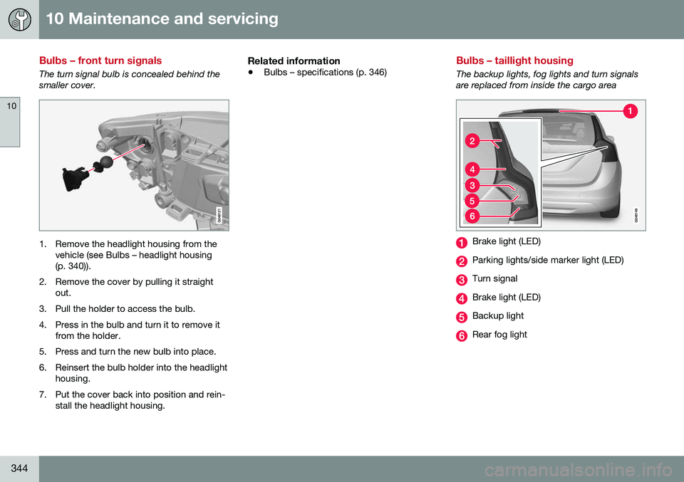
The turn signal bulb is concealed behind the smaller cover.
1. Remove the headlight housing from thevehicle (see Bulbs – headlight housing (p. 340)).
2. Remove the cover by pulling it straight out.
3. Pull the holder to access the bulb.
4. Press in the bulb and turn it to remove it from the holder.
5. Press and turn the new bulb into place.
6. Reinsert the bulb holder into the headlight housing.
7. Put the cover back into position and rein- stall the headlight housing.
Related information
• Bulbs – specifications (p. 346)
Bulbs – taillight housing
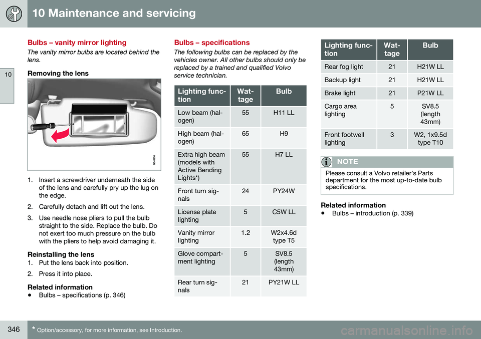
The backup lights, fog lights and turn signals are replaced from inside the cargo area
Brake light (LED)
Parking lights/side marker light (LED)
Turn signal
Brake light (LED)
Backup light
Rear fog light
Page 348 of 402

10 Maintenance and servicing
10
346* Option/accessory, for more information, see Introduction.
Bulbs – vanity mirror lighting
The vanity mirror bulbs are located behind the lens.
Removing the lens
1. Insert a screwdriver underneath the side
of the lens and carefully pry up the lug on the edge.
2. Carefully detach and lift out the lens.
3. Use needle nose pliers to pull the bulb straight to the side. Replace the bulb. Do not exert too much pressure on the bulbwith the pliers to help avoid damaging it.
Reinstalling the lens1. Put the lens back into position.
2. Press it into place.
Related information
• Bulbs – specifications (p. 346)
Bulbs – specifications
The following bulbs can be replaced by the vehicles owner. All other bulbs should only bereplaced by a trained and qualified Volvoservice technician.
Lighting func- tionWat-
tageBulb
Low beam (hal- ogen)55H11 LL
High beam (hal- ogen)65H9
Extra high beam (models withActive BendingLights*)55H7 LL
Front turn sig- nals24PY24W
License plate lighting5C5W LL
Vanity mirror lighting1.2W2x4.6d type T5
Glove compart- ment lighting5SV8.5
(length
43mm)
Rear turn sig- nals21PY21W LL
Lighting func- tionWat-
tageBulb
Rear fog light21H21W LL
Backup light21H21W LL
Brake light21P21W LL
Cargo area lighting5SV8.5
(length
43mm)
Front footwell lighting3W2, 1x9.5d type T10
NOTE
Please consult a Volvo retailer’s Parts department for the most up-to-date bulbspecifications.
Related information
• Bulbs – introduction (p. 339)
Page 367 of 402

10 Maintenance and servicing
10
}}
365
Automatic car wash
The vehicle should be washed at regular inter- vals since dirt, dust, insects and tar spotsadhere to the paint and may cause damage.To help prevent corrosion, it is particularlyimportant to wash the car frequently in thewintertime.• We do NOT recommend washing your car in an automatic wash during the firstfew months (because the paint will nothave hardened sufficiently).
• An automatic wash is a simple and quickway to clean your car, but it is worthremembering that it may not be as thor-ough as when you yourself go over thecar with sponge and water. Keeping theunderbody clean is most important, espe-cially in the winter. Some automaticwashers do not have facilities for washingthe underbody.
NOTE
Condensation may form temporarily on the inside of the lenses of exterior lights suchas headlights, fog lights, or taillights. Thisis normal and the lights are designed towithstand moisture. Normally, condensa-tion will dissipate after the lights have beenon for a short time.
CAUTION
• Before driving into an automatic car wash, turn off the optional rain sensorto avoid damaging the windshield wip-ers.
• Make sure that side view mirrors, aux-iliary lamps, etc, are secure, and thatany antenna(s) are retracted orremoved. Otherwise there is risk of themachine dislodging them.
• Chromed wheels:
Clean chrome-
plated wheels using the same deter-gents used for the body of the vehicle.Aggressive wheel-cleaning agents canpermanently stain chrome-platedwheels.
WARNING
• When the vehicle is driven immediately after being washed, apply the brakes,including the parking brake, severaltimes in order to remove any moisturefrom the brake linings.
• Engine cleaning agents should not beused when the engine is warm. Thisconstitutes a fire risk.
Related information
•
Polishing and waxing (p. 365)
• Cleaning the interior (p. 366)
• Washing the car (p. 364)
Polishing and waxing
Normally, polishing is not required during the first year after delivery, however, waxing maybe beneficial.
• Before applying polish or wax the vehicle must be washed and dried. Tar spots canbe removed with kerosene or tar remover.Difficult spots may require a fine rubbingcompound.
• After polishing use liquid or paste wax.
• Several commercially available productscontain both polish and wax.
• Waxing alone does not substitute for pol-ishing a dull surface.
• A wide range of polymer-based waxescan be purchased today. These waxesare easy to use and produce a long-last-ing, high-gloss finish that protects thebodywork against oxidation, road dirt andfading.
• Do not polish or wax your vehicle in directsunlight (the surface of the vehicle shouldnot be warmer than 113 °F (45 °C).
Page 388 of 402

||
11 Specifications
11
386* Option/accessory, for more information, see Introduction.
Symbols in the main instrument panel
Warning symbols in the instrument panel
SymbolDescriptionSee
Low oil pressure(p. 72)
Parking brake A(p. 72)
SRS airbags(p. 72)
Seat belt reminder(p. 72)
Generator not charg- ing(p. 72)
Fault in the brake sys- tem(p. 72)
Warning symbol(p. 72)
A
The symbol is Park only on models with the optional digital
instrument panel.
Related information
• Information displays – indicator symbols (p. 70)
• Information displays – warning symbols(p. 72)
• Information display – messages (p. 112)
Indicator symbols
The following tables list the most common warning and indicator lights and symbols anda reference to where more detailed informa-tion can be found.
: The red warning symbol illuminates to
indicate a problem related to safety and/or drivability. A message will also appear in themain instruments panel's display.
: The information symbol illuminates and
a text message is displayed to provide the driver with necessary information about oneof the vehicle's systems.
Indicator symbols in the instrument
panel
SymbolDescriptionSee
Fault in the Active Bending Light(ABL)*system(p. 70)
Malfunction indicator light(p. 70)
Anti-lock brake sys- tem (ABS)(p. 70)
Rear fog lights on(p. 70)
SymbolDescriptionSee
Stability system, Hill Descent Control,Trailer StabilityAssist*(p. 70)
Tire pressure moni- toring sensor (TPMS)(p. 70)
Low fuel level(p. 70)
Information symbol, see text in informa-tion display(p. 70)
High beam indicator(p. 70)
Left turn signal indi- cator(p. 70)
Right turn signal indi- cator(p. 70)
Stability system , Sport mode(p. 170)
Related information
• Information displays – indicator symbols (p. 70)
• Information displays – warning symbols(p. 72)
• Information display – messages (p. 112)
Page 394 of 402

12 Index
12
392
Electronic oil level sensor........................ 335
Electronic stability control....................... 169Emergency locking retractor...................... 47
Emergency starting.................................. 256
Emergency towing................... 289, 290, 291
Emission inspection readiness................ 330Engine overheating........................................... 73
specifications...................................... 379
Start/Stop........... 262, 263, 264, 265, 266
starting................................................ 252
switching off............................... 254, 255
Engine compartment overview................ 333
Engine Drag Control (EDC)...................... 170
Engine oil................................................. 380 checking............................................. 334
low pressure warning light.................... 72
volumes.............................................. 381
Engine remote start (ERS)........................ 254
Environment............................................... 22
F
Federal Clean Air Act............................... 327 Flat tires repairing with tire sealing system....... 319 Floor mats
cleaning.............................................. 367
placing correctly................................. 252
Fluid specifications.......................... 382, 383
Fog lights................................................... 71 rear........................................................ 92
Four C (active chassis system)................ 169
Front airbags.............................................. 33 disconnecting passenger’s side airbag 36
Front park assist.............................. 232, 240
Front seats................................................. 78 heated................................................. 127
Fuel filler cap........................................... 284
Fuel filler door, opening................... 283, 284
Fuel level warning light.............................. 71
Fuel requirements............................ 281, 282
Fuel tank volume..................................... 383
Fuses....................................... 354, 355, 361
G
Garage door opener HomeLink ®
Wireless Control
System........................................ 106, 107
Gasoline requirements............................. 282
Gas tank volume...................................... 383 Gauges...................................................... 66
Geartronic................................................ 259
Geartronic automatic transmission.......... 259
Generator warning light............................. 73
Glossary of tire terminology..................... 307
Grocery bag holder.................................. 141
Gross vehicle weight............................... 306
H
Hazard warning flashers............................ 93 Headlights
Active Bending Lights........................... 90
active high beams................................. 88
changing bulbs... 340, 341, 342, 343, 344
daytime running lights.......................... 87
high/low beams.................................... 88
high beam flash.................................... 88
tunnel detection.................................... 90
Headlight washers..................................... 97
Head restraints, rear seat.................... 82, 83
Heated front seats................................... 127
Heated oxygen sensors........................... 285
Heated rear seats.................................... 127
Heated steering wheel............................... 86
Heated windshield........................... 102, 129