2016 VOLVO S80 transmission oil
[x] Cancel search: transmission oilPage 10 of 380

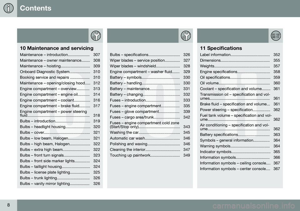
Contents
8
10
10 Maintenance and servicing
Maintenance – introduction.................... 307
Maintenance – owner maintenance........ 308
Maintenance – hoisting........................... 309
Onboard Diagnostic System................... 310
Booking service and repairs .................. 310
Maintenance – opening/closing hood..... 312
Engine compartment – overview............ 313
Engine compartment – engine oil........... 314
Engine compartment – coolant............... 316
Engine compartment – brake fluid.......... 317Engine compartment – power steering
fluid......................................................... 318
Bulbs – introduction................................ 319
Bulbs – headlight housing....................... 320
Bulbs – cover.......................................... 321
Bulbs – low beam, Halogen.................... 321
Bulbs – high beam, Halogen................... 322
Bulbs – extra high beam......................... 322
Bulbs – front turn signals........................ 323
Bulbs – front side marker lights.............. 324
Bulbs – taillight housing.......................... 324
Bulbs – license plate lighting.................. 325
Bulbs – trunk lighting.............................. 326
Bulbs – vanity mirror lighting.................. 326
10
Bulbs – specifications............................. 326
Wiper blades – service position.............. 327
Wiper blades – windshield...................... 328
Engine compartment – washer fluid....... 329
Battery – symbols................................... 330
Battery – handling................................... 330
Battery – maintenance............................ 331
Battery – changing.................................. 332
Fuses – introduction............................... 333
Fuses – engine compartment................. 335
Fuses – glove compartment................... 339
Fuses – cargo area/trunk........................ 342Fuses – engine compartment cold zone
(Start/Stop only)...................................... 343
Washing the car...................................... 345
Automatic car wash................................ 346
Polishing and waxing.............................. 346
Cleaning the interior................................ 347
Touching up paintwork........................... 349
11
11 Specifications
Label information.................................... 352
Dimensions............................................. 355
Weights................................................... 357
Engine specifications.............................. 358
Oil specifications..................................... 359
Oil volume............................................... 360
Coolant – specification and volume........ 361Transmission oil – specification and vol-
umes....................................................... 361
Brake fluid – specification and volume... 361
Power steering – specification................ 362Fuel tank volume – specification and vol-
ume......................................................... 362 Air conditioning – specification and vol-
ume......................................................... 362
Battery specifications............................. 363
Symbols – general information............... 364
Warning symbols.................................... 364
Indicator symbols.................................... 365
Information symbols............................... 366
Information symbols – ceiling console.... 367
Information symbols – center console.... 367
Page 236 of 380

||
08 Starting and driving
08
234
WARNING
•Always remove the remote key from the ignition slot when leaving the vehi-cle and ensure that the ignition inmode
0 (see Ignition modes (p. 73) for
information about the ignition modes).
• On vehicles with the optional keylessdrive, never remove the remote keyfrom the vehicle while it is being drivenor towed.
• Always place the gear selector in Parkand apply the parking brake beforeleaving the vehicle. Never leave thevehicle unattended with the enginerunning.
• Always open garage doors fully beforestarting the engine inside a garage toensure adequate ventilation. Theexhaust gases contain carbon monox-ide, which is invisible and odorless butvery poisonous.
NOTE
•
After a cold start, idle speed may be noticeably higher than normal for ashort period. This is done to help bringcomponents in the emission controlsystem to their normal operating tem-perature as quickly as possible, whichenables them to control emissions andhelp reduce the vehicle's impact on the environment 3
.
CAUTION
• When starting in cold weather, the automatic transmission may shift up atslightly higher engine speeds than nor-mal until the automatic transmissionfluid reaches normal operating tem-perature.
• Do not race a cold engine immediatelyafter starting. Oil flow may not reachsome lubrication points fast enough toprevent engine damage.
• The engine should be idling when youmove the gear selector. Never acceler-ate until after you feel the transmissionengage. Accelerating immediately afterselecting a gear will cause harshengagement and premature transmis-sion wear.
• Selecting
P or N when idling at a
standstill for prolonged periods of timewill help prevent overheating of theautomatic transmission fluid.
Related information
• Switching off the engine (p. 235)
3
If the gear selector is in the D or R positions and the car is not moving, engine speed (rpm) will be lower and it will take longer for the engine to reach normal operating temperature.
Page 252 of 380

08 Starting and driving
08
250
All Wheel Drive (AWD)
Your Volvo can be equipped with permanent All Wheel Drive, which means that power isdistributed automatically between the frontand rear wheels.
Under normal driving conditions, most of the engine's power is directed to the frontwheels. However, if there is any tendency forthe front wheels to spin, an electronicallycontrolled coupling distributes power to thewheels that have the best traction.
NOTE
The message AWD disabled Service
required will be appear in the information
display if an electrical fault should occur in the AWD system. A warning light will alsoilluminate in the instrument panel. If thisoccurs, have the system checked by atrained and qualified Volvo service techni-cian.
Related information
• Transmission – general information (p. 238)
Brakes – general
The brake system is a hydraulic system con- sisting of two separate brake circuits. If aproblem should occur in one of these circuits,it is still possible to stop the vehicle with theother brake circuit. If the brake pedal must be depressed farther than normal and requires greater foot pres-sure, the stopping distance will be longer. A warning light in the instrument panel will light up to warn the driver that a fault hasoccurred. If this light comes on while driving or braking, stop immediately and check the brake fluidlevel in the reservoir.
NOTE
Press the brake pedal hard and maintain pressure on the pedal – do not pump thebrakes.
WARNING
If the fluid level is below the
MIN mark in
the reservoir or if a brake system message is shown in the information display: DO
NOT DRIVE . Have the vehicle towed to a
trained and qualified Volvo service techni-cian and have the brake system inspected.
Page 260 of 380

08 Starting and driving
08
258
Driving through water
The vehicle should be driven with extreme caution if it is necessary to drive throughstanding water. The vehicle can be driven through water up to a depth of approximately 10 in. (25 cm) atwalking speed to help prevent water fromentering the differential and the transmission.This reduces the oil's lubricating capacity andmay shorten the service life of these compo-nents.
• Take particular care when driving through flowing water.
• Clean the electrical connections for trailerwiring after driving in mud or water.
• When driving through water, maintain lowspeed and do not stop in the water.WARNING
• Avoid driving through standing or rushing water. Doing so can be dan-gerous and it may also be difficult todetermine the actual depth of thewater.
• If water cannot be avoided, after driv-ing through the water, press lightly onthe brake pedal to ensure that thebrakes are functioning normally. Wateror mud can make the brake liningsslippery, resulting in delayed brakingeffect.
CAUTION
•
Engine damage will occur if water is drawn into the air cleaner.
• If the vehicle is driven through waterdeeper than 10 in (25 cm), water mayenter the differential and the transmis-sion. This reduces the oil's lubricatingcapacity and may shorten the servicelife of these components.
• Damage to any components, theengine, transmission, turbo-charger,differential or its internal componentscaused by flooding, vapor lock orinsufficient oil is not covered underwarranty.
• Do not allow the vehicle to stand inwater up to the door sills longer thanabsolutely necessary. This could resultin electrical malfunctions.
• If the engine has been stopped whilethe vehicle is in water, do not attemptto restart it. Have the vehicle towedout of the water.
Related information
•
Towing the vehicle (p. 269)
• Towing by tow truck (p. 271)
Page 261 of 380

08 Starting and driving
08
}}
259
Engine and cooling system
Under special conditions, for example when driving in hilly terrain, extreme heat or withheavy loads, there is a risk that the engine andcooling system will overheat. Proceed as follows to avoid overheating the engine. •Maintain a low speed when driving with a trailer up long, steep hills. For informa-tion, see Towing a trailer (p. 267)
• Do not turn the engine off immediatelywhen stopping after a hard drive.
WARNING
The cooling fan may start or continue to operate (for up to 6 minutes) after theengine has been switched off.
•
Remove any auxiliary lights from in front of the grille when driving in hot weatherconditions.
• Do not exceed engine speeds of4500 rpm if driving with a trailer in hillyterrain. The oil temperature could becometoo high.
Conserving electrical current
Keep the following in mind to help minimize battery drain:
• When the engine is not running, avoid using ignition mode
II. Many electrical
systems (the audio system, the optionalnavigation system, power windows, etc)will function in ignition modes 0 and I.
These modes reduce drain on the battery.
• Please keep in mind that using systems,accessories, etc., that consume a greatdeal of current when the engine is notrunning could result in the battery beingcompletely drained. Driving or having theengine running for approximately15 minutes will help keep the batterycharged.
• The optional 12-volt socket in thetrunk (p. 135) area provides electrical cur-rent even with the ignition switched off,which drains the battery.
Before a long distance trip
It is always worthwhile to have your vehicle checked by a trained and qualified Volvo serv-ice technician before driving long distances.Your retailer will also be able to supply youwith bulbs, fuses, spark plugs and wiperblades for your use in the event that problemsoccur. As a minimum, the following items should be checked before any long trip:
• Check that engine runs smoothly and that fuel consumption is normal.
• Check for fuel, oil, and fluid leakage.
• Have the transmission oil level (p. 362)checked.
• Check condition of drive belts.
• Check state of the battery's charge.
• Examine tires carefully (the spare tire aswell), and replace those that areworn (p. 275). Check tire pres-sure (p. 282).
• The brakes, front wheel alignment, andsteering gear should be checked by atrained and qualified Volvo service techni-cian only.
• Check all lights, including high beams.
• Reflective warning triangles are legallyrequired in some states/provinces.
• Have a word with a trained and qualifiedVolvo service technician if you intend to
Page 338 of 380

||
10 Maintenance and servicing
10
336* Option/accessory, for more information, see Introduction.
Engine compartment, upper
Engine compartment, front
Engine compartment, lower
PositionsThese fuses are all located in the engine com- partment box. Fuses in C are located under
A .
A decal on the inside of the cover shows thepositions of the fuses. • Fuses 1 – 15, 34 and 42 – 44 are relays/ circuit breakers and should only beremoved or replaced by a trained andqualified Volvo service technician.
• Fuses 16 – 33 and 35 – 41 may bechanged at any time when necessary.
There is a special fuse removal tool on the underside of the cover.
PosFunctionA
Circuit breaker: central electrical moduleunder the glove com- partment A50
Circuit breaker: central electrical moduleunder the glove com-partment50
PosFunctionA
Circuit breaker: central electrical module in the trunkA60
Circuit breaker: central electrical moduleunder the glove com- partment A60
Circuit breaker: central electrical moduleunder the glove com- partmentA60
–
–
Headed windshield*, driver's side40
Windshield wipers30
–
Climate system blowerA40
Headed windshield*, passenger's side40
ABS pump40
PosFunctionA
ABS valves20
Headlight washers20
Active Bending Lights- headlight leveling*10
Central electrical mod- ule (under the glovecompartment)20
ABS5
Adjustable steering force*5
Engine Control Module (ECM), transmission,SRS10
Heated washer noz- zles*10
-
Lighting panel5
-
-
-
Relay coils5
Page 339 of 380

10 Maintenance and servicing
10
}}
* Option/accessory, for more information, see Introduction.337
PosFunctionA
Auxiliary lights*20
Horn15
Relay coils, Engine Control Module (ECM)10
Control module - auto- matic transmission15
A/C compressor (not 4-cyl. engines)15
Relay-coils A/C, relay coils in engine com-partment cold zone forStart/Stop5
Starter motor relay A30
Engine control module (4-cyl. engines) Ignition coils (5-/6-cyl. engines), condenser(6-cyl. engines)20
Engine Control Module (4-cyl. engines)20
Engine Control Module (5-cyl. & 6-cyl. engines)10
PosFunctionA
4-cyl. engines: mass air meter, thermostat,EVAP valve10
5-/6-cyl. engines: Injection system, massair meter (6-cyl.engines only), enginecontrol module15
A/C compressor (5-/6- cyl. engines), enginevalves, engine controlmodule (6-cyl.engines), solenoids (6-cyl. non-turbo only),mass air meter (6-cyl.only), oil level sensor(5-cyl. only)10
Engine valves/oil pump/center heatedoxygen sensor (4-cyl.engines)15
Front/rear heated oxy- gen sensors (4-cyl.engines), EVAP valve(5-/6-cyl. engines),heated oxygen sensors(5-/6-cyl. engines)15
PosFunctionA
Oil pump/crankcase ventilation heater/cool-ant pump (5-cyl.engines)10
Ignition coils (4-cyl. engines)15
Fuel leakage detection (5-/6-cyl. engines),control module forradiator shutter (5-cyl.engines)5
Fuel leakage detection, A/C solenoid (4-cyl.engines)7.5
Coolant pump (4-cyl. engines)50
Cooling fan60 (4/5- cyl.engines)
80 (6-cyl. engines)
Power steering100
A
This position is not used on vehicles with the optional Start/Stop function, refer to the table "Engine compart-ment cold zone" in Fuses – engine compartment cold zone(Start/Stop only) (p. 343).
Page 363 of 380

11 Specifications
11
361
Coolant – specification and volume
The table lists coolant volumes and specifica- tions.
SystemVolumeSpecifica- tion
3.2 (6- cyl.)/3.0T9.4 US qts. (8.9 liters)Coolant with corrosioninhibitor mixedwith water(50/50 mix),see packag-ing.
All 4-cyl. engines8.8 US qts. (8.3 liters)
Related information
•Engine compartment – coolant (p. 316)
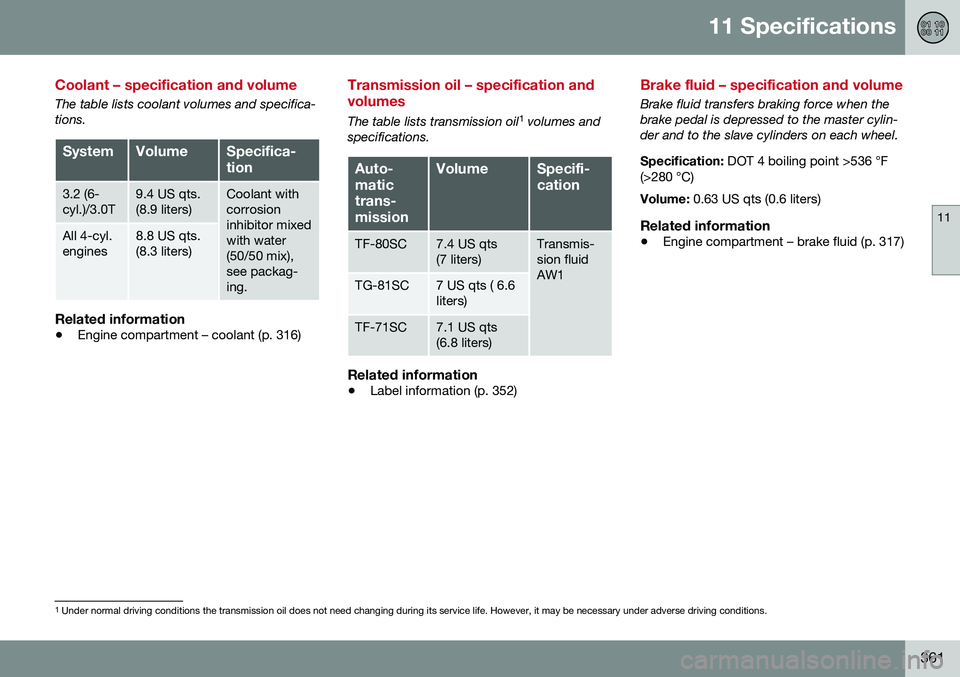
Transmission oil – specification and volumes
The table lists transmission oil 1
volumes and
specifications.
Auto- matictrans-missionVolumeSpecifi- cation
TF-80SC7.4 US qts (7 liters)Transmis- sion fluidAW1
TG-81SC7 US qts ( 6.6 liters)
TF-71SC7.1 US qts (6.8 liters)
Related information
• Label information (p. 352)
Brake fluid – specification and volume
Brake fluid transfers braking force when the brake pedal is depressed to the master cylin-der and to the slave cylinders on each wheel. Specification:
DOT 4 boiling point >536 °F
(>280 °C) Volume: 0.63 US qts (0.6 liters)
Related information
•Engine compartment – brake fluid (p. 317)
1
Under normal driving conditions the transmission oil does not need changing during its service life. However, it may be necessary under adverse driving conditions.