2016 VAUXHALL MOVANO_B air suspension
[x] Cancel search: air suspensionPage 42 of 233
40Seats, restraintsSeat adjustment9Danger
Do not sit nearer than 25 cm from
the steering wheel, to permit safe
airbag deployment.
9 Warning
Never adjust seats while driving as
they could move uncontrollably.
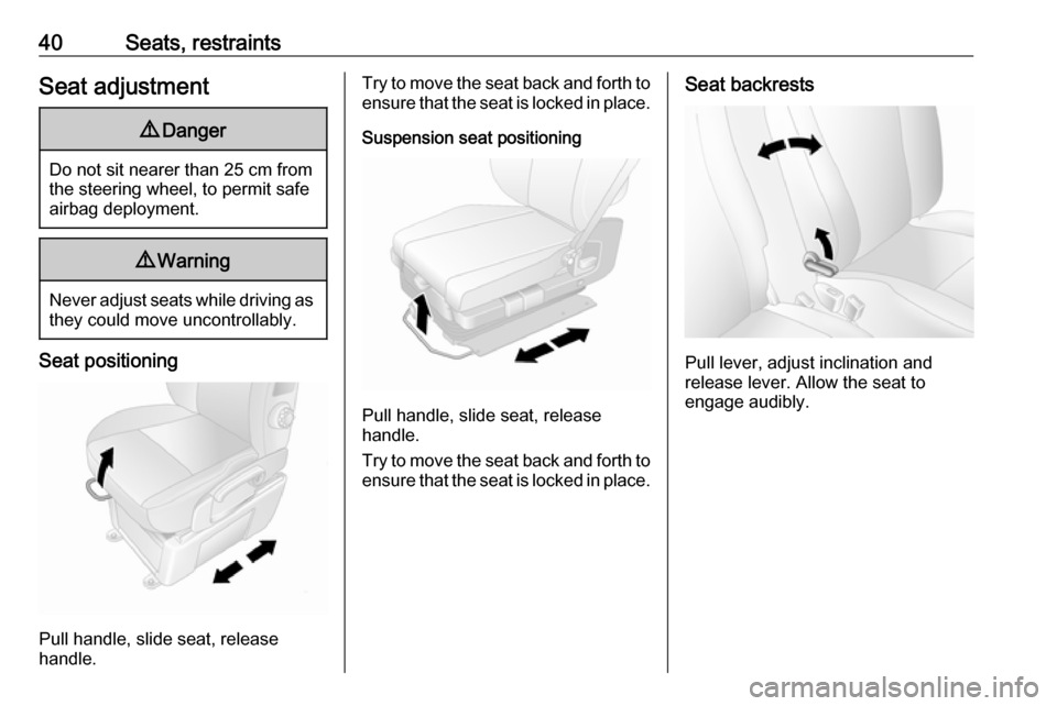
Seat positioning
Pull handle, slide seat, release
handle.
Try to move the seat back and forth to ensure that the seat is locked in place.
Suspension seat positioning
Pull handle, slide seat, release
handle.
Try to move the seat back and forth to ensure that the seat is locked in place.
Seat backrests
Pull lever, adjust inclination and
release lever. Allow the seat to
engage audibly.
Page 117 of 233

Driving and operating115Driving and
operatingDriving hints ............................... 116
Driving economically ...............116
Control of the vehicle ...............116
Steering ................................... 116
Starting and operating ...............117
New vehicle running-in ............117
Ignition switch positions ...........117
Starting the engine ..................118
Idle speed control ....................118
Overrun cut-off ........................ 119
Stop-start system ....................119
Parking .................................... 121
Air suspension ......................... 122
Engine exhaust .......................... 124
Diesel particle filter ..................124
Catalytic converter ...................124
AdBlue ..................................... 125
Manual transmission ..................130
Manual transmission automa‐ ted .............................................. 130
Transmission display ...............130
Starting the engine ..................131
Selector lever .......................... 131Manual mode........................... 132
Electronic driving programmes 132
Fault ........................................ 133
Interruption of power supply ....134
Brakes ........................................ 134
Antilock brake system .............134
Parking brake .......................... 135
Brake assist ............................. 136
Hill start assist ......................... 136
Ride control systems .................136
Traction Control system ..........136
Electronic stability program .....137
Driver assistance systems .........139
Cruise control .......................... 139
Speed limiter ........................... 142
Parking assist .......................... 142
Rear view camera ...................144
Lane departure warning ..........146
Fuel ............................................ 148
Fuel for diesel engines ............148
Refuelling ................................ 148
Fuel consumption - CO 2-
Emissions .............................. 149
Trailer hitch ................................ 150
General information .................150
Driving characteristics and towing tips .............................. 150
Trailer towing ........................... 150Towing equipment ...................151
Trailer stability assist ...............151
Auxiliary features .......................152
Power take-off ......................... 152
Page 124 of 233

122Driving and operatingfirst gear. On an uphill slope,
turn the front wheels away from
the kerb.
If the vehicle is on a downhill
slope, engage reverse gear.
Turn the front wheels towards
the kerb.
● Close the windows.
● Turn the ignition key to position
0 and remove it. Turn the
steering wheel until the
steering wheel lock is felt to
engage.
Lock the vehicle 3 21 and activate the
anti-theft locking system 3 30 and
anti-theft alarm system 3 31.
Air suspension
Operates automatically when the
vehicle is driven. The air suspension
system constantly adjusts the ride
height according to the vehicle load.
Caution
To ensure safe operation of the air
suspension system, do not exceed the maximum permissible gross
vehicle weight rating. Refer to
identification plate 3 199 or the
vehicle documents.
For further information on the air
suspension system, refer to the
operating instructions supplied.
Master switch
Caution
The air suspension system must
be switched off when the vehicle is being towed, jump‐started, raised
off the ground or transported.
Do not switch off the air
suspension system when driving.
Jump starting 3 188, Towing the
vehicle 3 190.
The master switch is located on the
door pillar.
Switch on to enable operation and
adjustment of the air suspension
system.
Page 126 of 233
124Driving and operatingWhen service mode has been
activated, the air suspension master switch must be turned off.
To exit service mode, press i again
for 5 seconds.
Fault
If a fault is detected, i will flash
intermittently. If service mode has been activated and there is a fault, h,
S and R will flash simultaneously.
Have the cause of the fault remedied
by a workshop.Engine exhaust9 Danger
Engine exhaust gases contain
poisonous carbon monoxide,
which is colourless and odourless and could be fatal if inhaled.
If exhaust gases enter the interior
of the vehicle, open the windows.
Have the cause of the fault
rectified by a workshop.
Avoid driving with an open load
compartment, otherwise exhaust
gases could enter the vehicle.
Diesel particle filter
The diesel particle filter system filters
harmful soot particles out of the
exhaust gases. The system includes
a self-cleaning function that runs
automatically during driving without
any notification.
The filter is cleaned by periodically
burning off the soot particles at high
temperature. This process takes
place automatically under set driving
conditions. Autostop is not available
and fuel consumption may be higher
during this period. The emission of
smells and smoke during this process is normal.
Under certain driving conditions, e.g.
short distances, the system cannot
clean itself automatically.
If cleaning of the filter is required and
if previous driving conditions did not
enable automatic cleaning, it will be
indicated by illumination of control
indicator A 3 85. Seek the
assistance of a workshop
immediately.Caution
If the cleaning process is
interrupted, there is a risk of
provoking severe engine damage.
Cleaning takes place quickest at high engine speeds and loads.
Catalytic converter
The catalytic converter reduces the
amount of harmful substances in the
exhaust gases.
Page 174 of 233

172Vehicle careSymbolCircuitZInfotainment system / Seat
heating / Vehicle display
screen / Audio connec‐
tions / Alarm?Power outletÌCigarette lightereInstrument panelUCentral locking0Interior lightsOTurn signals / Rear fog
lights / Body control moduleDIAGDiagnostic connectoruABS / Electronic Stability
ProgramdInterior lights / Brake lightsZBody control moduleSTOPBrake lightIBody control module /
Power windows / Heating
and ventilation system / Air
conditioningSymbolCircuitmLeft heated rear windownRight heated rear windowRWindscreen washerMElectronic immobiliserUHeated seatsFBLCornering lightlHands-free connection&TachographPTOPower take-offjHornÍPreheating / Diesel fuel filterxClimate control fandHeated exterior mirrorsTLeft-hand side lightSRight-hand side lightQPneumatic suspensionONavigation systemSymbolCircuitADPAdditional adaptations,Power windows / Body
control module
Load compartment fuse box
Combi
Located behind the trim panel on the
right-hand side of the load
compartment, beside the rear door.
Page 186 of 233
184Vehicle careWheel changingSome vehicles are equipped with a
tyre repair kit instead of a spare wheel
3 180.
Make the following preparations and
observe the following information:
● Park the vehicle on a level, firm and non-slippery surface. The
front wheels must be in the
straight-ahead position.
● Apply the parking brake and engage first gear or reverse gear
(manual transmission) or N
(manual transmission
automated).
● Switch off the air suspension system 3 122.
● Remove the spare wheel 3 185.
● Never change more than one wheel at a time.
● Use the jack only to change wheels in case of puncture, not
for seasonal winter or summer
tyre change.
● The jack is maintenance-free.● If the ground on which the vehicle
is standing is soft, a solid board
(max. 1 cm thick) should be
placed under the jack.
● No people or animals may be in the vehicle when it is jacked-up.
● Never crawl under a jacked-up vehicle.
● Do not start the engine when the vehicle is raised on the jack.
● Clean wheel bolts/nuts and their threads before mounting thewheel.9 Warning
Do not grease wheel bolt, wheel
nut and wheel nut cone.
1. Remove the wheel cover using the hook supplied. Vehicle tools
3 174.
2. Install the wheel wrench ensuring that it locates securely and loosen
each wheel bolt/nut by half a turn.
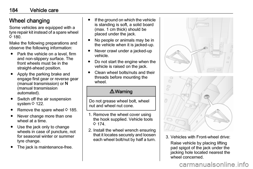
3. Vehicles with Front-wheel drive:
Raise vehicle by placing lifting
pad spigot of the jack under the
jacking hole located nearest the
wheel concerned.
Page 190 of 233
188Vehicle careThe following applies to tyres fitted
opposing the rolling direction:
● Driveability may be affected. Have the defective tyre renewed
or repaired as soon as possible.
● Do not drive faster than 50 mph.
● Drive particularly carefully on wet
and snow-covered road
surfaces.Jump starting
Do not start with a quick charger.
A vehicle with a discharged battery
can be started using jump leads and
the battery of another vehicle.9 Warning
Be extremely careful when starting
with jump leads. Any deviation
from the following instructions can
lead to injuries or damage caused
by battery explosion or damage to the electrical systems of both
vehicles.
9 Warning
Avoid contact with eyes, skin,
fabrics, and painted surfaces. The fluid contains sulphuric acid which can cause injuries and damage in
the event of direct contact.
Caution
The air suspension system must
be switched off prior to jump
starting.
9 Warning
Avoid contact of the battery with
eyes, skin, fabrics and painted
surfaces. The fluid contains
sulphuric acid which can cause
injuries and damage in the event
of direct contact.
● Never expose the vehicle battery
to naked flames or sparks.
● A discharged vehicle battery can already freeze at a temperature
of 0 °C. Defrost the frozen vehicle
battery before connecting jump leads.
● Wear eye protection and protective clothing when
handling a vehicle battery.
Page 191 of 233
Vehicle care189● Use a booster battery with thesame voltage (12 volts). Its
capacity (Ah) must not be much less than that of the discharged
vehicle battery.
● Use jump leads with insulated terminals and a cross section of
at least 25 mm 2
.
● Do not disconnect the discharged
battery from the vehicle.
● Switch off all unnecessary electrical consumers.
● Switch off the air suspension system 3 122.
● Do not lean over the vehicle battery during jump starting.
● Do not allow the terminals of one
lead to touch those of the other
lead.
● The vehicles must not come into contact with each other during
the jump starting process.
● Apply the parking brake and engage neutral (manual
transmission) or N (manual
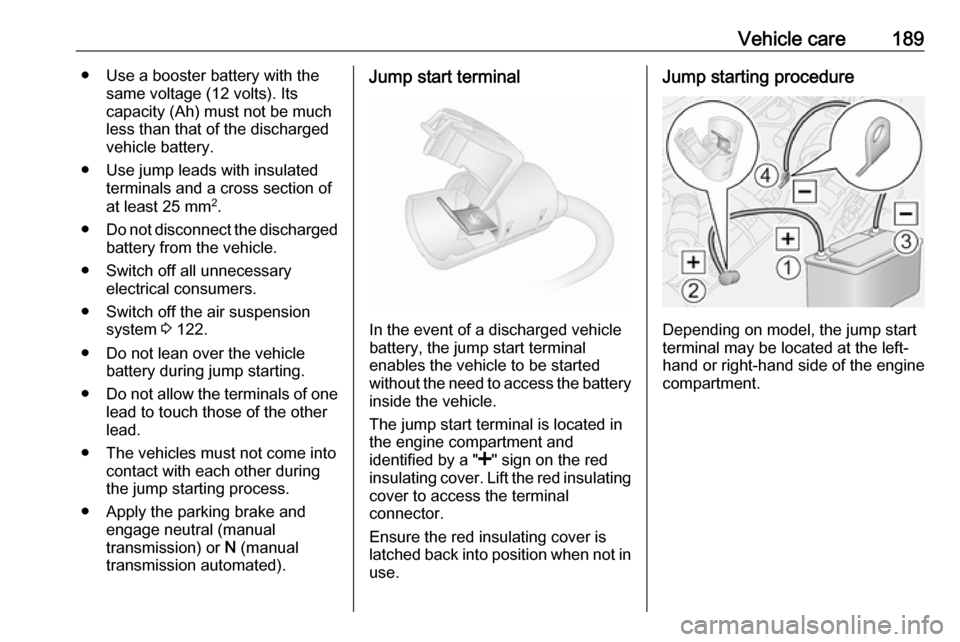
transmission automated).Jump start terminal
In the event of a discharged vehicle
battery, the jump start terminal
enables the vehicle to be started
without the need to access the battery inside the vehicle.
The jump start terminal is located in
the engine compartment and
identified by a " <" sign on the red
insulating cover. Lift the red insulating
cover to access the terminal
connector.
Ensure the red insulating cover is
latched back into position when not in
use.
Jump starting procedure
Depending on model, the jump start
terminal may be located at the left-
hand or right-hand side of the engine
compartment.