2016 VAUXHALL MOVANO_B brake light
[x] Cancel search: brake lightPage 134 of 233

132Driving and operatingwarning may sound as a signal to
depress the brake pedal or apply the
parking brake.
Switch off engine if stopping for a
lengthy period, e.g. in traffic jams.
When the vehicle is parked and the
driver's door is opened, a warning
chime will sound if neutral is not
selected or the brake pedal has not
been depressed.
Engine braking
Automatic mode
When driving downhill, the manual
transmission automated does not
shift into higher gears until a fairly
high engine speed has been reached. It shifts down in good time when
braking.
Manual mode
To utilise the engine braking effect,
select a lower gear in good time when
driving downhill.Rocking the vehicle
Rocking the vehicle is only
permissible if the vehicle is stuck in
sand, mud, snow or a hole. Move the
selector lever between R and A/M (or
between + and -) in a repeat pattern,
while applying light pressure to the
accelerator pedal. Do not race the
engine and avoid sudden
acceleration.
Parking
Apply the parking brake. The most
recently engaged gear (see
transmission display) remains
engaged. With N, no gear is engaged.
When the ignition is switched off, the
transmission no longer responds to
movement of the selector lever.
If the ignition is not switched off, or the
parking brake has not been applied, a
warning chime will sound upon
opening the driver's door.
Manual mode If a higher gear is selected when the
engine speed is too low, or a lower
gear when the speed is too high, theshift is not executed. This prevents
the engine from running at too low or too high an engine speed.
If engine speed is too low, the
transmission automatically shifts to a
lower gear.
If engine speed is too high, the
transmission only switches to a higher gear via kickdown.
Electronic driving programmes
Winter mode V
Page 137 of 233

Driving and operating1359Warning
If there is a fault in the ABS, the
wheels may be liable to lock due
to braking that is heavier than
normal. The advantages of ABS are no longer available. During
hard braking, the vehicle can no longer be steered and may
swerve.
If control indicators u, A , R and
C illuminate, the ABS and ESP are
deactivated and the message
BRAKING FAULT is shown in the
DIC. Seek the assistance of a
workshop.
Have the cause of the fault remedied by a workshop.
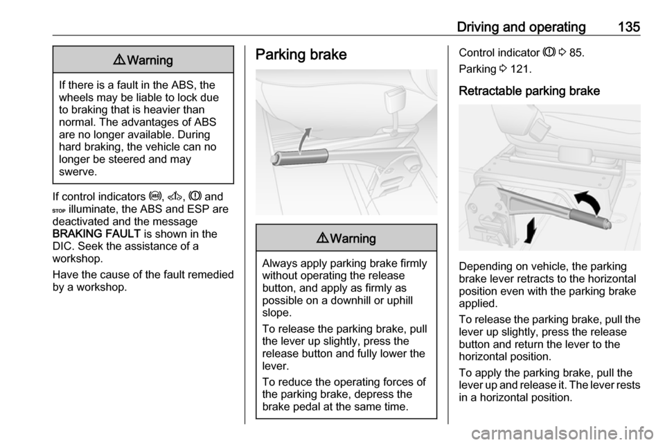
Parking brake9 Warning
Always apply parking brake firmly
without operating the release
button, and apply as firmly as
possible on a downhill or uphill
slope.
To release the parking brake, pull
the lever up slightly, press the
release button and fully lower the
lever.
To reduce the operating forces of
the parking brake, depress the
brake pedal at the same time.
Control indicator R 3 85.
Parking 3 121.
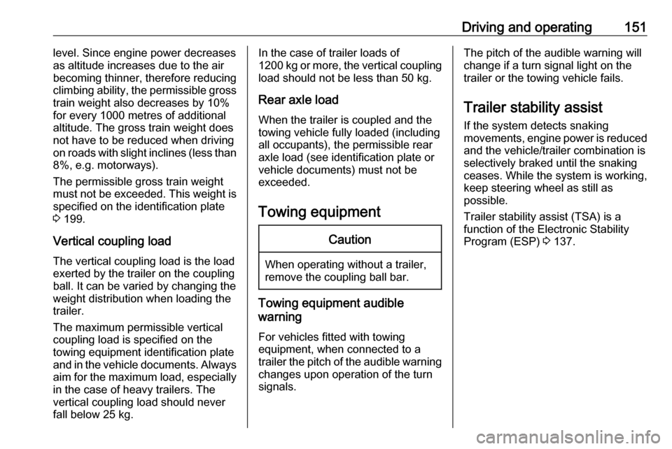
Retractable parking brake
Depending on vehicle, the parking
brake lever retracts to the horizontal
position even with the parking brake
applied.
To release the parking brake, pull the lever up slightly, press the release
button and return the lever to the
horizontal position.
To apply the parking brake, pull the
lever up and release it. The lever rests
in a horizontal position.
Page 152 of 233

150Driving and operatingGeneral information
The official fuel consumption and
specific CO 2 emission figures quoted
relate to the EU base model with
standard equipment.
Fuel consumption data and CO 2
emission data are determined
according to regulation
715/2007 692/2008 A, taking into
consideration the vehicle weight in
running order, as specified by the
regulation.
The figures must not be taken as a
guarantee for the actual fuel
consumption of a particular vehicle.
Additional equipment may result in
slightly higher results than the stated
consumption and CO 2 figures.
Furthermore, fuel consumption is
dependent on personal driving style
as well as road and traffic conditions.Trailer hitch
General information
Only use towing equipment that has
been approved for your vehicle.
Entrust fitting of towing equipment at
a later date to a workshop. It may be
necessary to make changes that
affect the cooling system, heat
shields or other equipment.
Driving characteristics and towing tips
In the case of trailers with brakes,
attach the breakaway stopping cable.
Before attaching a trailer, lubricate
the coupling ball. However, do not do
so if a stabiliser, which acts on the coupling ball, is being used to reduce snaking movements. For trailers with
low driving stability the use of a
stabiliser is recommended.
A maximum speed of 50 mph must
not be exceeded, even in countries
where higher speeds are permitted.If the trailer starts snaking, drive more slowly, do not attempt to correct the
steering and brake sharply if
necessary.
When driving downhill, drive in the
same gear as if driving uphill and
drive at a similar speed.
Adjust tyre pressure to the value
specified for full load 3 219.
Trailer towing Trailer loadsThe permissible trailer loads are
vehicle-dependent and engine-
dependent maximum values which
must not be exceeded. The actual
trailer load is the difference between
the actual gross weight of the trailer
and the actual coupling socket load
with the trailer coupled.
The permissible trailer loads are
specified in the vehicle documents. In
general, they are valid for gradients
up to max. 12%.
The permitted trailer load applies up
to the specified incline and up to an
altitude of 1000 metres above sea
Page 153 of 233

Driving and operating151level. Since engine power decreases
as altitude increases due to the air
becoming thinner, therefore reducing
climbing ability, the permissible gross
train weight also decreases by 10%
for every 1000 metres of additional
altitude. The gross train weight does
not have to be reduced when driving
on roads with slight inclines (less than
8%, e.g. motorways).
The permissible gross train weight
must not be exceeded. This weight is
specified on the identification plate
3 199.
Vertical coupling load
The vertical coupling load is the load
exerted by the trailer on the coupling
ball. It can be varied by changing the
weight distribution when loading the
trailer.
The maximum permissible vertical
coupling load is specified on the
towing equipment identification plate
and in the vehicle documents. Always aim for the maximum load, especially
in the case of heavy trailers. The
vertical coupling load should never
fall below 25 kg.In the case of trailer loads of
1200 kg or more, the vertical coupling load should not be less than 50 kg.
Rear axle load
When the trailer is coupled and the
towing vehicle fully loaded (including
all occupants), the permissible rear
axle load (see identification plate or
vehicle documents) must not be
exceeded.
Towing equipmentCaution
When operating without a trailer,
remove the coupling ball bar.
Towing equipment audible
warning
For vehicles fitted with towing
equipment, when connected to a
trailer the pitch of the audible warning
changes upon operation of the turn
signals.
The pitch of the audible warning will
change if a turn signal light on the
trailer or the towing vehicle fails.
Trailer stability assist
If the system detects snaking
movements, engine power is reduced
and the vehicle/trailer combination is
selectively braked until the snaking ceases. While the system is working,keep steering wheel as still as
possible.
Trailer stability assist (TSA) is a
function of the Electronic Stability
Program (ESP) 3 137.
Page 155 of 233

Vehicle care153Vehicle careGeneral Information...................154
Accessories and vehicle modifications .......................... 154
Vehicle storage ........................154
End-of-life vehicle recovery .....155
Vehicle checks ........................... 155
Performing work ......................155
Bonnet ..................................... 155
Engine oil ................................. 156
Engine coolant ......................... 157
Power steering fluid .................158
Washer fluid ............................ 159
Brakes ..................................... 159
Brake fluid ............................... 159
Vehicle battery ......................... 159
Diesel fuel filter ........................161
Diesel fuel system bleeding .....161
Wiper blade replacement ........162
Bulb replacement .......................162
Headlights ............................... 162
Adaptive forward lighting .........164
Fog lights ................................. 165
Front turn signal lights .............165
Tail lights ................................. 166
Side turn signal lights ..............167Centre high-mounted brake
light ......................................... 167
Number plate light ...................168
Interior lights ............................ 168
Instrument panel illumination ...169
Electrical system ........................170
Fuses ....................................... 170
Engine compartment fuse box . 171
Instrument panel fuse box .......171
Load compartment fuse box ....172
Vehicle tools .............................. 174
Tools ........................................ 174
Wheels and tyres .......................175
Tyres ....................................... 175
Winter tyres ............................. 176
Tyre designations ....................176
Tyre pressure .......................... 176
Tyre pressure monitoring system .................................... 177
Tread depth ............................. 179
Changing tyre and wheel size . 179 Wheel covers ........................... 180
Tyre chains .............................. 180
Tyre repair kit .......................... 180
Wheel changing .......................184
Spare wheel ............................ 185
Jump starting ............................. 188Towing....................................... 190
Towing the vehicle ...................190
Towing another vehicle ...........191
Appearance care .......................192
Exterior care ............................ 192
Interior care ............................. 193
Page 168 of 233

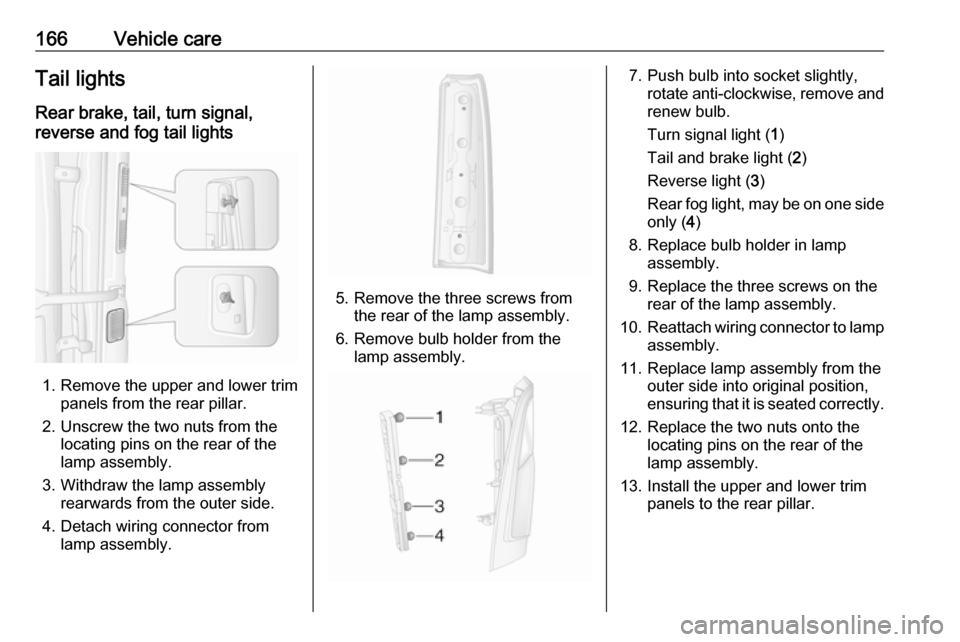
166Vehicle careTail lightsRear brake, tail, turn signal,
reverse and fog tail lights
1. Remove the upper and lower trim panels from the rear pillar.
2. Unscrew the two nuts from the locating pins on the rear of the
lamp assembly.
3. Withdraw the lamp assembly rearwards from the outer side.
4. Detach wiring connector from lamp assembly.
5. Remove the three screws from the rear of the lamp assembly.
6. Remove bulb holder from the lamp assembly.
7. Push bulb into socket slightly, rotate anti-clockwise, remove and
renew bulb.
Turn signal light ( 1)
Tail and brake light ( 2)
Reverse light ( 3)
Rear fog light, may be on one side only ( 4)
8. Replace bulb holder in lamp assembly.
9. Replace the three screws on the rear of the lamp assembly.
10. Reattach wiring connector to lamp
assembly.
11. Replace lamp assembly from the outer side into original position,
ensuring that it is seated correctly.
12. Replace the two nuts onto the locating pins on the rear of the
lamp assembly.
13. Install the upper and lower trim panels to the rear pillar.
Page 169 of 233

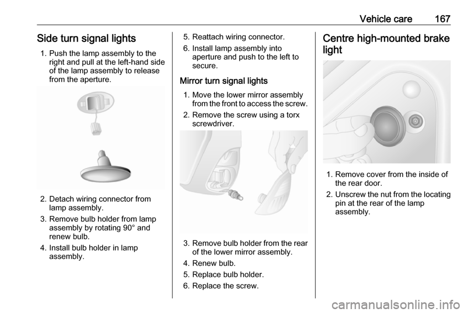
Vehicle care167Side turn signal lights1. Push the lamp assembly to the right and pull at the left-hand side
of the lamp assembly to release
from the aperture.
2. Detach wiring connector from lamp assembly.
3. Remove bulb holder from lamp assembly by rotating 90° and
renew bulb.
4. Install bulb holder in lamp assembly.
5. Reattach wiring connector.
6. Install lamp assembly into aperture and push to the left to
secure.
Mirror turn signal lights 1. Move the lower mirror assembly from the front to access the screw.
2. Remove the screw using a torx screwdriver.
3. Remove bulb holder from the rear
of the lower mirror assembly.
4. Renew bulb.
5. Replace bulb holder.
6. Replace the screw.
Centre high-mounted brake
light
1. Remove cover from the inside of the rear door.
2. Unscrew the nut from the locating
pin at the rear of the lamp
assembly.
Page 174 of 233

172Vehicle careSymbolCircuitZInfotainment system / Seat
heating / Vehicle display
screen / Audio connec‐
tions / Alarm?Power outletÌCigarette lightereInstrument panelUCentral locking0Interior lightsOTurn signals / Rear fog
lights / Body control moduleDIAGDiagnostic connectoruABS / Electronic Stability
ProgramdInterior lights / Brake lightsZBody control moduleSTOPBrake lightIBody control module /
Power windows / Heating
and ventilation system / Air
conditioningSymbolCircuitmLeft heated rear windownRight heated rear windowRWindscreen washerMElectronic immobiliserUHeated seatsFBLCornering lightlHands-free connection&TachographPTOPower take-offjHornÍPreheating / Diesel fuel filterxClimate control fandHeated exterior mirrorsTLeft-hand side lightSRight-hand side lightQPneumatic suspensionONavigation systemSymbolCircuitADPAdditional adaptations,Power windows / Body
control module
Load compartment fuse box
Combi
Located behind the trim panel on the
right-hand side of the load
compartment, beside the rear door.