Page 181 of 608

LC200_OM_OM60M88U_(U)
1814-1. Before driving
4
Driving
●A recommended tongue weight varies in accordance with the types
of trailers or towing as described below.
● To ensure the recommended values shown below, the trailer must
be loaded by referring to the following instructions.
• Tongue Weight
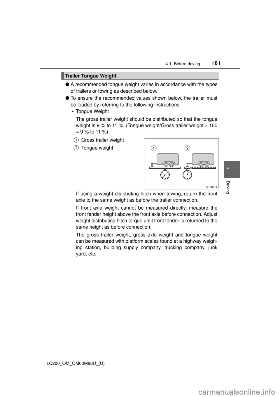
The gross trailer weight should be distributed so that the tongue
weight is 9 % to 11 %. (Tongue weight/Gross trailer weight 100
= 9 % to 11 %)
Gross trailer weight
Tongue weight
If using a weight distributing hitch when towing, return the front
axle to the same weight as before the trailer connection.
If front axle weight cannot be measured directly, measure the
front fender height above the front axle before connection. Adjust
weight distributing hitch torque until front fender is returned to the
same height as before connection.
The gross trailer weight, gross axle weight and tongue weight
can be measured with platform scales found at a highway weigh-
ing station, building supply company, trucking company, junk
yard, etc.
Trailer Tongue Weight
1
2
Page 358 of 608
358
LC200_OM_OM60M88U_(U)
4-5. Using the driving support systems
◆VGRS (Variable Gear Ratio Steering)
Helps to adjust the wheel turning angle in accordance with the vehicle
speed and steering wheel movement.
◆Trailer Sway Control
Helps the driver to control trailer sw ay by selectively applying brake pres-
sure for individual wheels and reducing engine torque when trailer sway is
detected.
Trailer Sway Control is part of the VSC system and will not operate if VSC
turned off or experiences a malfunction.
The slip indicator light flashes to
indicate that the VSC/Trailer
Sway Control/Active TRAC/hill-
start assist control systems have
been engaged.
The stop lights and high mounted
stoplight turn on when the hill-start
assist control system or Trailer
Sway Control is operating.
When the Active TRAC/VSC/Trailer Sway Control/hill-start assist
control systems are operating
Page 533 of 608

5337-2. Steps to take in an emergency
LC200_OM_OM60M88U_(U)
7
When trouble arises
WARNING
■Replacing a flat tire
●Observe the following precautions.
Failure to do so may result in serious injury:
• Lower the spare tire completely to the ground before removing it from under the vehicle.
• Do not try to remove the wheel ornament by hand. Take due care in
handling the ornament to avoid unexpected personal injury.
• Do not touch the disc wheels or the area around the brakes immedi-
ately after the vehicle has been driven.
After the vehicle has been driven the disc wheels and the area
around the brakes will be extremely hot. Touching these areas with
hands, feet or other body parts wh ile changing a tire, etc. may result
in burns.
●Failure to follow these precautions could cause the wheel nuts to
loosen and the tire to fall off, resulting in death or serious injury.
• Have the wheel nuts tightened with a torque wrench to 97 ft•lbf (131 N•m, 13.4 kgf•m) as soon as possible after changing wheels.
• Do not attach a heavily damaged wheel ornament, as it may fly off
the wheel while the vehicle is moving.
• When installing a tire, only use wh eel nuts that have been specifi-
cally designed for that wheel.
• If there are any cracks or deforma tions in the bolt screws, nut
threads or bolt holes of the wheel, have the vehicle inspected by
your Toyota dealer.
• When installing the wheel nuts, be sure to install them with the tapered ends facing inward. ( P. 476)
Page 534 of 608
5347-2. Steps to take in an emergency
LC200_OM_OM60M88U_(U)
Remove any dirt or foreign mat-
ter from the wheel contact sur-
face.
If foreign matter is on the wheel
contact surface, the wheel nuts
may loosen while the vehicle is in
motion, and the tire may come off
the vehicle.
Install the spare tire and loosely
tighten each nut by hand to
approximately the same
amount.
Turn the lug nuts until the wash-
ers come into contact with the
disc wheel.
Lower the vehicle.
Firmly tighten each nut two or
three times in the order shown
in the illustration.
Tightening torque:
97 ft•lbf (131 N•m, 13.4 kgf•m)
Installing the spare tire
1
Washer
Disc wheel
2
3
4
Page 558 of 608

558
LC200_OM_OM60M88U_(U)
8-1. Specifications
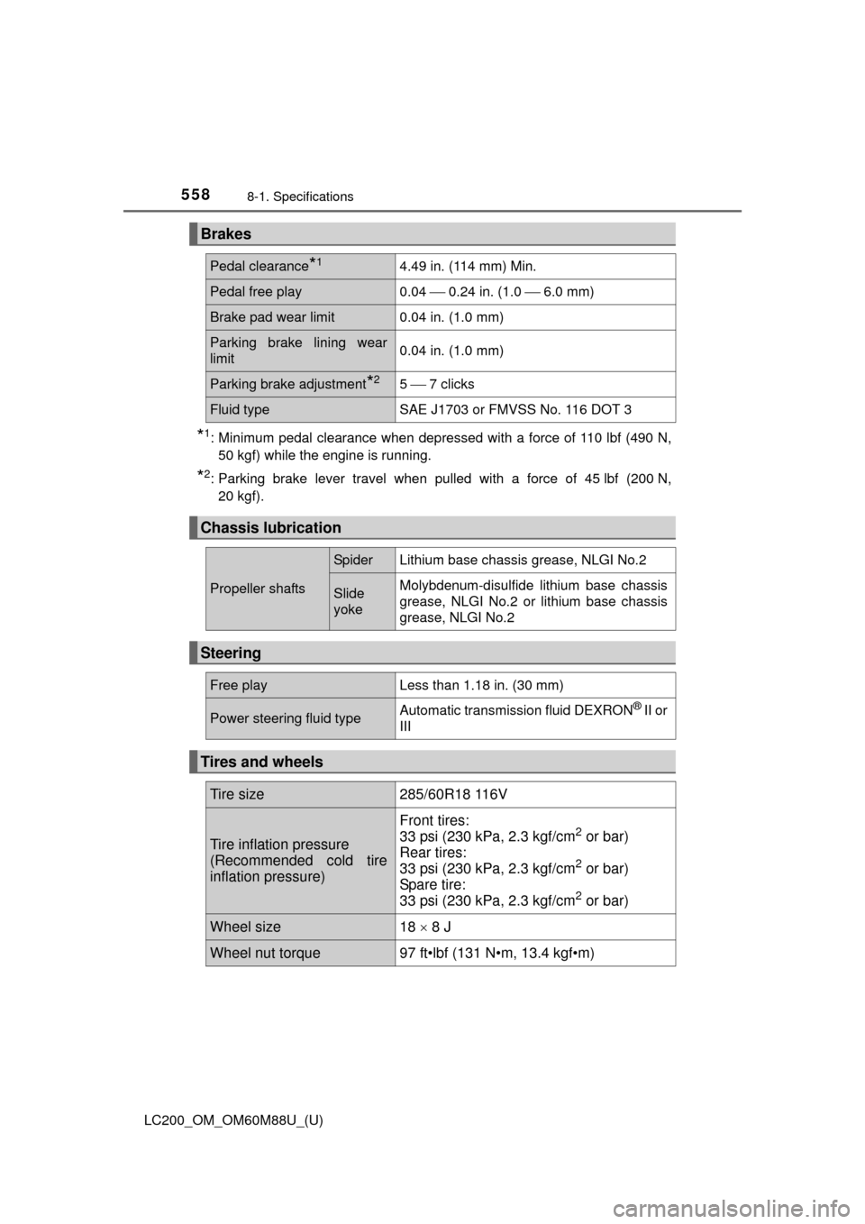
*1: Minimum pedal clearance when depressed with a force of 110 lbf (490 N,50 kgf) while the engine is running.
*2: Parking brake lever travel when pulled with a force of 45 lbf (200 N,20 kgf).
Brakes
Pedal clearance*14.49 in. (114 mm) Min.
Pedal free play0.04 0.24 in. (1.0 6.0 mm)
Brake pad wear limit0.04 in. (1.0 mm)
Parking brake lining wear
limit0.04 in. (1.0 mm)
Parking brake adjustment*25 7 clicks
Fluid typeSAE J1703 or FMVSS No. 116 DOT 3
Chassis lubrication
Propeller shafts
SpiderLithium base chassis grease, NLGI No.2
Slide
yokeMolybdenum-disulfide lithium base chassis
grease, NLGI No.2 or lithium base chassis
grease, NLGI No.2
Steering
Free playLess than 1.18 in. (30 mm)
Power steering fluid typeAutomatic transmission fluid DEXRON® II or
III
Tires and wheels
Tire size285/60R18 116V
Tire inflation pressure
(Recommended cold tire
inflation pressure)
Front tires:
33 psi (230 kPa, 2.3 kgf/cm2 or bar)
Rear tires:
33 psi (230 kPa, 2.3 kgf/cm
2 or bar)
Spare tire:
33 psi (230 kPa, 2.3 kgf/cm
2 or bar)
Wheel size18 8 J
Wheel nut torque97 ft•lbf (131 N•m, 13.4 kgf•m)