Page 533 of 620

5338-2. Steps to take in an emergency
8
When trouble arises
COROLLA_TMMMS_TMMC_U (OM12J84U)
One of the following may be the cause of the problem:
lOne or both of the battery terminals may be disconnected.
l The battery may be discharged. ( P. 538)
l There may be a malfunction in the steering lock system (vehicles
with a smart key system).
Contact your Toyota dealer if the problem cannot be repaired, or if repair
procedures are unknown.
When the engine does not start, the following steps can be used as an
interim measure to start the engine if the engine switch is functioning
normally:
Set the parking brake.
Shift the shift lever to P (continuously variable transmission) or N
(manual transmission).
Turn the engine switch to ACCESSORY mode.
Press and hold the engine switch for about 15 seconds while
depressing the brake pedal and cl utch pedal (manual transmission)
firmly.
Even if the engine can be started using the above steps, the system
may be malfunctioning. Have the v ehicle inspected by your Toyota
dealer.
The starter motor does not turn ov er, the interior lights and head-
lights do not turn on, or the horn does not sound.
Emergency start function (vehicles with a smart key system)
1
2
3
4
Page 534 of 620
5348-2. Steps to take in an emergency
COROLLA_TMMMS_TMMC_U (OM12J84U)
Set the parking brake.
Vehicles without a smart key system: Turn the engine switch to the
“ACC” position.
Vehicles with a smart key system: Turn the engine switch to
ACCESSORY mode.
Depress the brake pedal.
Pry the cover up with a flathead
screwdriver or equivalent tool.
To prevent damage to the cover,
cover the tip of the screwdriver with
a rag.
Press the shift lock override
button.
The shift lever can be shifted while
the button is pressed.
If the shift lever cannot be shifted from P
(except vehicles with a manual transmission)
If the shift lever cannot be sh ifted with your foot on the brake
pedal, there may be a problem with the shift lock system (a sys-
tem to prevent accidental operation of the shift lever). Have the
vehicle inspected by your Toyota dealer immediately.
The following steps may be used as an emergency measure to
ensure that the shift lever can be shifted:
1
2
3
4
5
Page 536 of 620

5368-2. Steps to take in an emergency
COROLLA_TMMMS_TMMC_U (OM12J84U)
Continuously variable transmission: Ensure that the shift lever is in
P and depress the brake pedal.
Manual transmission: Shift the shift lever to N and depress the
clutch pedal.
Touch the Toyota emblem side
of the electronic key to the
engine switch.
When the electronic key is
detected, a buzzer sounds and the
engine switch will turn to IGNITION
ON mode.
When the smart key system is
deactivated in customization set-
ting, the engine switch will turn to
ACCESSORY mode.
Vehicles with a drive monitor display: Firmly depress the brake
pedal (continuously variable transm ission) or clutch pedal (manual
transmission) and check that the smart key system indicator light
(green) turns on.
Vehicles with a multi- information display: Firmly depress the brake
pedal (continuously variable transm ission) or clutch pedal (manual
transmission) and check that is shown on the multi-informa-
tion display.
Press the engine switch.
In the event that the engine still c annot be started, contact your Toyota
dealer.
Starting the engine
1
2
3
4
Page 537 of 620

5378-2. Steps to take in an emergency
8
When trouble arises
COROLLA_TMMMS_TMMC_U (OM12J84U)
nStopping the engine
Shift the shift lever to P (continuously variable transmission) or N (manual
transmission) and press the engine switch as you normally do when stopping
the engine.
n Replacing the key battery
As the above procedure is a temporary measure, it is recommended that the
electronic key battery be replaced immediately when the battery is depleted.
( P. 469)
n Changing engine switch modes
Release the brake pedal (continuously variable transmission) or clutch pedal
(manual transmission) and press the engine switch in step above.
The engine does not start and modes will be changed each time the switch is
pressed. ( P. 170)
n When the electronic key does not work properly
lMake sure that the smart key system has not been deactivated in the cus-
tomization setting. If it is off, turn the function on.
(Customizable features P. 576)
l Check if battery-saving mode is set. If it is set, cancel the function.
(P. 118)
3
Page 547 of 620
5478-2. Steps to take in an emergency
8
When trouble arises
COROLLA_TMMMS_TMMC_U (OM12J84U)
Stop the engine. Set the parking brake and shift the shift lever to P
(automatic transmission or continuously variable transmission) or N
(manual transmission).
Remove the mud, snow or sand from around the front wheels.
Place wood, stones or some othe r material under the front wheels
to help provide traction.
Restart the engine.
Shift the shift lever to D or R (automatic transmission or continu-
ously variable transmission) or 1 or R (manual transmission) and
release the parking brake. Then, while exercising caution, depress
the accelerator pedal.
If the vehicle becomes stuck
Carry out the following procedures if the tires spin or the vehicle
becomes stuck in mud, dirt or snow:
1
2
3
4
5
Page 557 of 620
5579-1. Specifications
9
Vehicle specifications
COROLLA_TMMMS_TMMC_U (OM12J84U)
*1: Minimum pedal clearance when depressed with a force of 66 lbf (294 N, 30kgf) while the engine is running
*2: Parking brake lever travel when pulled up with a force of 44 lbf (200 N, 20kgf)
Brakes
Pedal clearance*1
1.8 L 4-cylinder (2ZR-FE) engine
2.9 in. (74 mm)
1.8 L 4-cylinder (2ZR-FAE) engine
2.8 in. (71 mm)
Pedal free play 0.04 0.24 in. (1 6 mm)
Brake pad wear limit0.04 in. (1.0 mm)
Parking brake lining wear limit0.04 in. (1.0 mm)
Parking brake lever travel*26 9 clicks
Fluid type SAE J1703 or FMVSS No.116 DOT 3
Page 570 of 620

5709-1. Specifications
COROLLA_TMMMS_TMMC_U (OM12J84U)
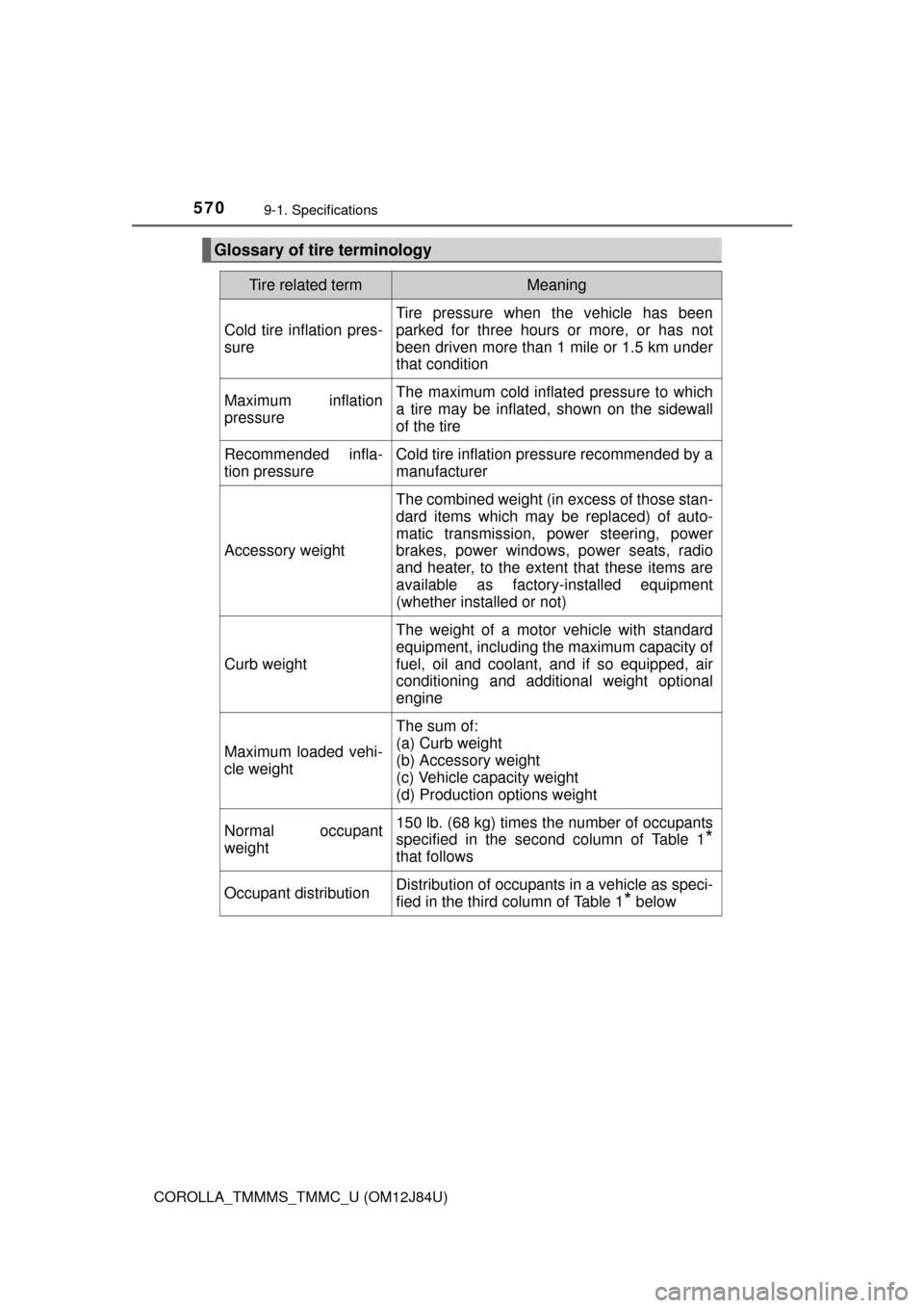
Glossary of tire terminology
Tire related termMeaning
Cold tire inflation pres-
sure
Tire pressure when the vehicle has been
parked for three hours or more, or has not
been driven more than 1 mile or 1.5 km under
that condition
Maximum inflation
pressureThe maximum cold inflated pressure to which
a tire may be inflated, shown on the sidewall
of the tire
Recommended infla-
tion pressureCold tire inflation pressure recommended by a
manufacturer
Accessory weight
The combined weight (in excess of those stan-
dard items which may be replaced) of auto-
matic transmission, power steering, power
brakes, power windows, power seats, radio
and heater, to the extent that these items are
available as factory-installed equipment
(whether installed or not)
Curb weight
The weight of a motor vehicle with standard
equipment, including the maximum capacity of
fuel, oil and coolant, and if so equipped, air
conditioning and additional weight optional
engine
Maximum loaded vehi-
cle weight
The sum of:
(a) Curb weight
(b) Accessory weight
(c) Vehicle capacity weight
(d) Production options weight
Normal occupant
weight150 lb. (68 kg) times the number of occupants
specified in the second column of Table 1
*
that follows
Occupant distributionDistribution of occupants in a vehicle as speci-
fied in the third column of Table 1
* below
Page 571 of 620

5719-1. Specifications
9
Vehicle specifications
COROLLA_TMMMS_TMMC_U (OM12J84U)
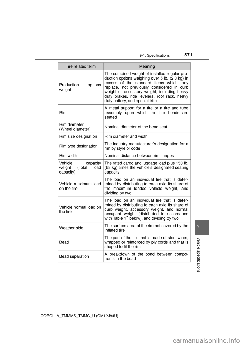
Production options
weight
The combined weight of installed regular pro-
duction options weighing over 5 lb. (2.3 kg) in
excess of the standard items which they
replace, not previously considered in curb
weight or accessory weight, including heavy
duty brakes, ride levelers, roof rack, heavy
duty battery, and special trim
Rim
A metal support for a tire or a tire and tube
assembly upon which the tire beads are
seated
Rim diameter
(Wheel diameter)Nominal diameter of the bead seat
Rim size designationRim diameter and width
Rim type designationThe industry manufacturer’s designation for a
rim by style or code
Rim widthNominal distance between rim flanges
Vehicle capacity
weight (Total load
capacity)The rated cargo and luggage load plus 150 lb.
(68 kg) times the vehicle’s designated seating
capacity
Vehicle maximum load
on the tire
The load on an individual tire that is deter-
mined by distributing to each axle its share of
the maximum loaded vehicle weight, and
dividing by two
Vehicle normal load on
the tire
The load on an individual tire that is deter-
mined by distributing to each axle its share of
curb weight, accessory weight, and normal
occupant weight (distributed in accordance
with Table 1
* below), and dividing by two
Weather sideThe surface area of the rim not covered by the
inflated tire
Bead
The part of the tire that is made of steel wires,
wrapped or reinforced by ply cords and that is
shaped to fit the rim
Bead separationA breakdown of the bond between compo-
nents in the bead
Tire related termMeaning