2016 SUBARU WRX towing
[x] Cancel search: towingPage 468 of 594

The temporary spare tire is smaller and
lighter than a conventional tire and is
designed for emergency use only. Re-
move the temporary spare tire and re-
install the conventional tire as soon as
possible because the spare tire is de-
signed only for temporary use.
Check the inflation pressure of the tem-
porary spare tire periodically to keep the
tire ready for use. The correct pressure is
as follows.
Mexico models: 33 psi (230 kPa, 2.3
kgf/cm 2
)
Other models: 60 psi (420 kPa, 4.2
kgf/cm 2
)
When using the temporary spare tire, note
the following.
. Do not exceed 50 mph (80 km/h).
. Do not put a tire chain on the temporary
spare tire. Because of the smaller tire size,
a tire chain will not fit properly.
. Do not use two or more temporary
spare tires at the same time.
. Do not drive over obstacles. This tire
has a smaller diameter, so road clearance
is reduced. 1) Tread wear indicator bar
2) Indicator location mark
. When the wear indicator appears on
the tread, replace the tire.
. The temporary spare tire must be used
only on a rear wheel. If a front wheel tire
gets punctured, replace the wheel with a
rear wheel and install the temporary spare
tire in place of the removed rear wheel.
. Always set the driver ’ s control center
differential to the manual mode and adjust
the initial LSD torque to the minimum. Maintenance tools Your vehicle is equipped with the following
maintenance tools.
. Jack
. Jack handle
. Screwdriver
. Towing hook (eye bolt)
. Wheel nut wrench In case of emergency/Maintenance tools
– CONTINUED –9-3
Page 469 of 594

In case of emergency/Flat tires
1) Jack handle
1) Under-floor storage compartment (if
equipped) (Refer to “ Under-floor storage
compartment ” F 6-12.)
2) Tool bucket
3) Spare tire 1) Wheel nut wrench
2) Screwdriver
3) Jack
4) Towing hook (eye bolt)
A jack handle is stored under the floor of
the trunk. A jack and a towing hook are
stored in the tool bucket that is located in
the recess of the spare tire wheel. A
screwdriver and a wheel nut wrench are
stored in the vinyl bag. These tools can
also be stored in the tool bucket.
NOTE For how to use the jack, refer to “ Flat
tires ” F 9-4. Flat tires If you have a flat tire while driving, never
brake suddenly; keep driving straight
ahead while gradually reducing speed.
Then slowly pull off the road to a safe
place.
& Changing a flat tire WARNING. Do not jack up the vehicle on an
incline or a loose road surface.
The jack can come out of the
jacking point or sink into the
ground and this can result in a
severe accident.
. Use only the jack provided with
your vehicle. The jack supplied
with the vehicle is designed only
for changing a tire. Never get
under the vehicle while support-
ing the vehicle with this jack.9-4
Page 477 of 594

In case of emergency/Towing
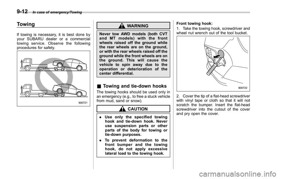
Towing If towing is necessary, it is best done by
your SUBARU dealer or a commercial
towing service. Observe the following
procedures for safety. WARNINGNever tow AWD models (both CVT
and MT models) with the front
wheels raised off the ground while
the rear wheels are on the ground,
or with the rear wheels raised off the
ground while the front wheels are on
the ground. This will cause the
vehicle to spin away due to the
operation or deterioration of the
center differential.
& Towing and tie-down hooks The towing hooks should be used only in
an emergency (e.g., to free a stuck vehicle
from mud, sand or snow).
CAUTION
. Use only the specified towing
hook and tie-down hook. Never
use suspension parts or other
parts of the body for towing or
tie-down purposes.
. To prevent deformation to the
front bumper and the towing
hook, do not apply excessive
lateral load to the towing hook. Front towing hook:
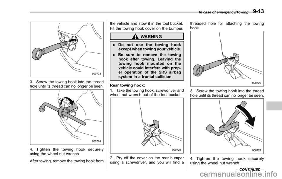
1. Take the towing hook, screwdriver and
wheel nut wrench out of the tool bucket.
2. Cover the tip of a flat-head screwdriver
with vinyl tape or cloth so that it will not
scratch the bumper. Insert the flat-head
screwdriver into the cutout of the cover
and pry open the cover.9-12
Page 478 of 594

3. Screw the towing hook into the thread
hole until its thread can no longer be seen.
4. Tighten the towing hook securely
using the wheel nut wrench.
After towing, remove the towing hook from the vehicle and stow it in the tool bucket.
Fit the towing hook cover on the bumper.
WARNING. Do not use the towing hook
except when towing your vehicle.
. Be sure to remove the towing
hook after towing. Leaving the
towing hook mounted on the
vehicle could interfere with prop-
er operation of the SRS airbag
system in a frontal collision.
Rear towing hook:
1. Take the towing hook, screwdriver and
wheel nut wrench out of the tool bucket.
2. Pry off the cover on the rear bumper
using a screwdriver, and you will find a threaded hole for attaching the towing
hook.
3. Screw the towing hook into the thread
hole until its thread can no longer be seen.
4. Tighten the towing hook securely
using the wheel nut wrench. In case of emergency/Towing
– CONTINUED –9-13
Page 479 of 594

In case of emergency/Towing
After towing, remove the towing hook from
the vehicle and stow it in the tool bucket.
Fit the towing hook cover on the bumper.
WARNINGDo not use the towing hook except
when towing your vehicle.
Be sure to remove the towing hook
after towing. Leaving the towing
hook mounted on the vehicle could
interfere with proper operation of
the fuel pump shut off function
when the vehicle is struck from
behind.
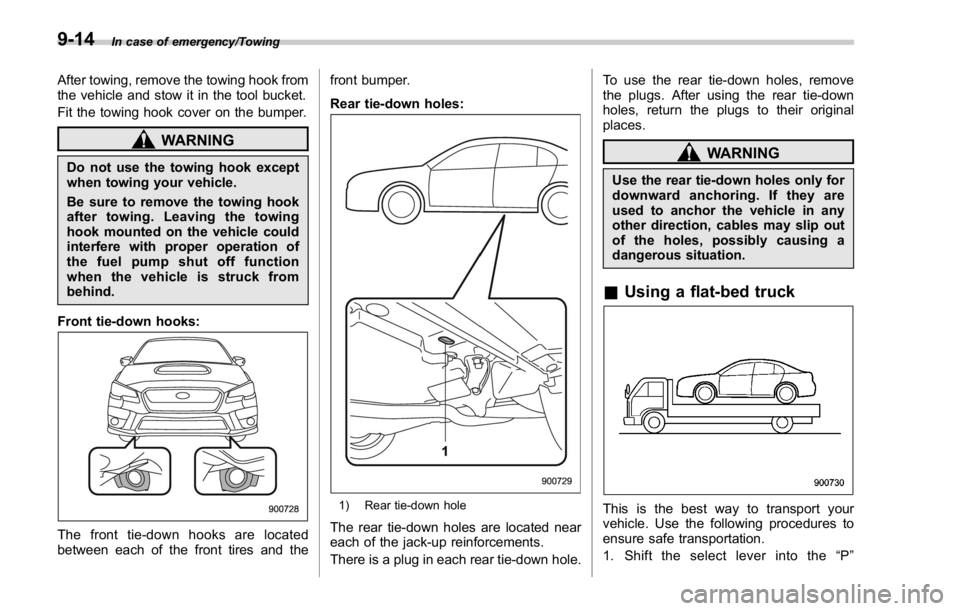
Front tie-down hooks:
The front tie-down hooks are located
between each of the front tires and the front bumper.
Rear tie-down holes:
1) Rear tie-down hole
The rear tie-down holes are located near
each of the jack-up reinforcements.
There is a plug in each rear tie-down hole. To use the rear tie-down holes, remove
the plugs. After using the rear tie-down
holes, return the plugs to their original
places.
WARNINGUse the rear tie-down holes only for
downward anchoring. If they are
used to anchor the vehicle in any
other direction, cables may slip out
of the holes, possibly causing a
dangerous situation.
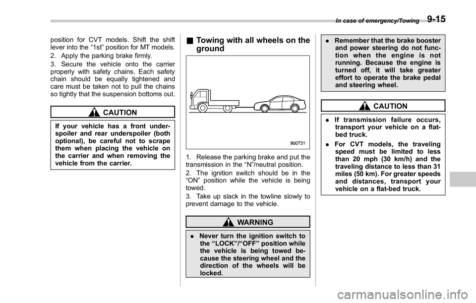
& Using a flat-bed truck
This is the best way to transport your
vehicle. Use the following procedures to
ensure safe transportation.
1. Shift the select lever into the “ P ”9-14
Page 480 of 594

position for CVT models. Shift the shift
lever into the “ 1st ” position for MT models.
2. Apply the parking brake firmly.
3. Secure the vehicle onto the carrier
properly with safety chains. Each safety
chain should be equally tightened and
care must be taken not to pull the chains
so tightly that the suspension bottoms out.
CAUTIONIf your vehicle has a front under-
spoiler and rear underspoiler (both
optional), be careful not to scrape
them when placing the vehicle on
the carrier and when removing the
vehicle from the carrier. & Towing with all wheels on the
ground
1. Release the parking brake and put the
transmission in the “ N ” /neutral position.
2. The ignition switch should be in the
“ ON ” position while the vehicle is being
towed.
3. Take up slack in the towline slowly to
prevent damage to the vehicle.
WARNING
. Never turn the ignition switch to
the “ LOCK ” / “ OFF ” position while
the vehicle is being towed be-
cause the steering wheel and the
direction of the wheels will be
locked. . Remember that the brake booster
and power steering do not func-
tion when the engine is not
running. Because the engine is
turned off, it will take greater
effort to operate the brake pedal
and steering wheel.
CAUTION. If transmission failure occurs,
transport your vehicle on a flat-
bed truck.
. For CVT models, the traveling
speed must be limited to less
than 20 mph (30 km/h) and the
traveling distance to less than 31
miles (50 km). For greater speeds
and distances, transport your
vehicle on a flat-bed truck. In case of emergency/Towing
9-15
Page 573 of 594

Consumer information and Reporting safety defects/Uniform tire quality grading standards
.
Vehicle stability will deteriorate..
Heavy and/or high-mounted
loads could increase the risk of
rollover. .
Stopping distance will increase..
Brakes could overheat and fail..
Suspension, bearings, axles and
other body parts could break or
experience accelerated wear that
will shorten vehicle life. .
Tires could fail..
Tread separation could occur..
Tire could separate from its rim.
& Steps for Determining Cor-
rect Load Limit1.
Locate the statement “ The com-
bined weight of occupants and
cargo should never exceed XXX
kg or XXX lbs. ” on your vehicle ’ s
placard.
2.
Determine the combined weight
of the driver and passengers that
will be riding in your vehicle.
3.
Subtract the combined weight of
the driver and passengers from
XXX kg or XXX lbs. 4.
The resulting figure equals the
available amount of cargo and
luggage load capacity. For exam-
ple, if the “ XXX ” amount equals
1400 lbs. and there will be five 150
lb passengers in your vehicle, the
amount of available cargo and
luggage load capacity is 650 lbs.
(1400 − 750 (5 6 150) = 650 lbs.)5.
Determine the combined weight
of luggage and cargo being loaded
on the vehicle. That weight may not
safely exceed the available cargo
and luggage load capacity calcu-
lated in Step 4.
6.
If your vehicle will be towing a
trailer, load from your trailer will be
transferred to your vehicle. Consult
this manual to determine how this
reduces the available cargo and
luggage load capacity of your ve-
hicle. Uniform tire quality grading
standards This information indicates the rela-
tive performance of passenger car
tires in the area of treadwear,
traction, and temperature resis-
tance. This is to aid the consumer
in making an informed choice in the
purchase of tires.
Quality grades can be found where
applicable on the tire sidewall be-
tween tread shoulder and maxi-
mum section width. For example:
Treadwear 200 Traction AA Tem-
perature A
The quality grades apply to new
pneumatic tires for use on passen-
ger cars. However, they do not
apply to deep tread, winter type
snow tires, space-saver or tempor-
ary use spare tires, tires with
nominal rim diameters of 12 inches
or less, or to some limited produc-
tion tires.
All passenger car tires must con-13-14
Page 581 of 594

14-6 Index
Bulb wattage ....................................................... 12-16
Control switch ........................................................ 3-94
Flasher ................................................................. 3-96
Indicator light ......................................................... 3-35
HID headlights .......................................................... 11-44
High beam indicator light ............................................ 3-35
High/low beam change (dimmer) .................................. 3-96
Hill Holder ................................................................. 7-46
Indicator light ................................................. 3-24, 7-48
Switch .................................................................. 7-47
Hill start assist .................................................. 7-49, 11-29
OFF indicator light .................................................. 3-24
To activate/deactivate ............................................. 7-51
Warning light ......................................................... 3-24
HomeLink ®
.............................................................. 3-105
Hook
Coat ..................................................................... 6-11
Towing and tie-down ............................................... 9-12
Horn ........................................................................ 3-114
Hose and connections ............................................... 11-17
I
Ignition switch .............................................................. 3-4
Light ....................................................................... 3-6
Illumination brightness control ...................................... 3-98
Immobilizer. ................................................................. 2-3
Indicator light (security indicator light) ....................... 3-33
Indicator light
BSD/RCTA OFF. .................................................... 3-37
BSD/RCTA warning ................................................ 3-37
Cruise control ........................................................ 3-35 Cruise control set ................................................... 3-35
Front fog light ......................................................... 3-35
Headlight ............................................................... 3-35
High beam ............................................................. 3-35
Hill Holder ............................................................. 3-24
Hill start assist OFF ................................................ 3-24
Immobilizer ............................................................ 3-33
REV. ..................................................................... 3-37
Security ................................................................. 3-33
Select lever/Gear position ........................................ 3-34
Shift-up ................................................................. 3-34
SI-DRIVE .............................................................. 3-34
Steering responsive fog lights OFF ... ........................ 3-37
Traction control OFF ............................................... 3-27
Turn signal ............................................................ 3-35
Vehicle Dynamics Control OFF ................................. 3-27
Vehicle Dynamics Control operation .......................... 3-26
Inside mirror ............................................................ 3-103
Interior lights ............................................................... 6-2
Internal trunk lid release handle .................................... 2-37
J
Jack-up point .............................................................. 9-4
Jump starting .............................................................. 9-9
K
Key............................................................................ 2-3
Number .................................................................. 2-3
Reminder chime ...................................................... 3-5
Replacement. .......................................................... 2-4
Keyless access entry function ...................................... 2-13