2016 SUBARU IMPREZA trailer
[x] Cancel search: trailerPage 162 of 594
NOTE
This light also illuminates when the fuel
filler cap is not tightened until it clicks.
If you have recently refueled your vehicle,
the cause of the CHECK ENGINE warning
light/malfunction indicator light illuminating
could be a loose or missing fuel filler cap.
Remove the cap and retighten it until it
clicks. Make sure nothing is interfering
with the sealing of the cap. Tightening the
cap will not make the CHECK ENGINE
warning light turn off immediately. It may
take several driving trips. If the light does
not turn off, take your vehicle to your
authorized SUBARU dealer immediately.
!If the light is blinking
If the light is blinking while driving, an
engine misfire condition has been de-
tected which may damage the emission
control system.
To prevent serious damage to the emis-
sion control system, you should do the
following.
. Reduce vehicle speed.
. Avoid hard acceleration.
. Avoid steep uphill grades.
. Reduce the amount of cargo, if possi-
ble.
. If towing a trailer, stop doing so as soon
as possible (trailer towing permitted with
Crosstrek models only). The CHECK ENGINE warning light may
stop blinking and illuminate steadily after
several driving trips. You should have your
vehicle checked by an authorized
SUBARU dealer immediately.
&Coolant temperature
low indicator light/Cool-
ant temperature high
warning light
CAUTION
.
After turning the ignition switch
to the “ON ”position, if this
indicator light/warning light be-
haves in any of the following
ways, the electrical system may
be malfunctioning. Contact your
SUBARU dealer immediately for
an inspection.
– It remains blinking in RED.
– It remains illuminated in RED
for more than 2 seconds.
– It remains blinking in RED and
BLUE alternately.
. While driving, if this indicator
light/warning light behaves in
any of the following ways, take
the specified appropriate mea-
sure listed below. –
Blinking or illuminated in
RED:
Safely stop the vehicle as
soon as possible, and refer
to the emergency steps to
take in the case of engine
overheating. After that, have
the system checked by your
nearest SUBARU dealer. Refer
to “Engine overheating ”F9-
13.
– Blinking in RED and BLUE
alternately:
The electrical system may be
malfunctioning. Contact your
SUBARU dealer for an inspec-
tion.
This coolant temperature low indicator
light/coolant temperature high warning
light has the following three functions.
. Illumination in BLUEindicates insuffi-
cient warming up of the engine
. Blinking in REDindicates that the
engine is close to overheating
. Illumination in REDindicates overheat-
ing condition of the engine
For a system check, this indicator light/
warning light illuminates in REDfor
approximately 2 seconds when the igni-
tion switch is turned to the “ON”position.
Instruments and controls/Warning and indicator lights
–CONTINUED –3-17
Page 421 of 594
Starting and operating/Vehicle Dynamics Control system
–The brake pedal seems to jolt
when driving off after starting the
engine.
. In the circumstances shown in the
following list, the vehicle may be less
stable than it feels to the driver. The
Vehicle Dynamics Control System may
therefore operate. Such operation does
not indicate a system malfunction.
–on gravel-covered or rutted
roads
– on unfinished roads
– when the vehicle is towing a
trailer (trailer towing permitted with
Crosstrek models only)
– when the vehicle is fitted with
snow tires or winter tires
. Activation of the Vehicle Dynamics
Control system will cause operation of
the steering wheel to feel slightly
different compared to that for normal
conditions.
. It is always important to reduce
speed when approaching a corner,
even if your vehicle is equipped with
the Vehicle Dynamics Control system.
. Always turn off the engine before
replacing a tire. Failure to do so may
render the Vehicle Dynamics Control
system unable to operate correctly.& Vehicle Dynamics Control
system monitor
Refer to “Vehicle Dynamics Control warn-
ing light/Vehicle Dynamics Control opera-
tion indicator light ”F 3-24 and “Vehicle
Dynamics Control OFF indicator light ”F 3-
25.
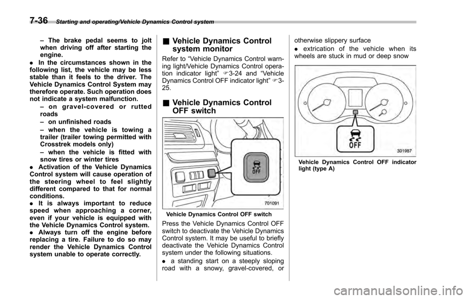
& Vehicle Dynamics Control
OFF switch
Vehicle Dynamics Control OFF switch
Press the Vehicle Dynamics Control OFF
switch to deactivate the Vehicle Dynamics
Control system. It may be useful to briefly
deactivate the Vehicle Dynamics Control
system under the following situations.
. a standing start on a steeply sloping
road with a snowy, gravel-covered, or otherwise slippery surface
.
extrication of the vehicle when its
wheels are stuck in mud or deep snow
Vehicle Dynamics Control OFF indicator
light (type A)
7-36
Page 430 of 594
Cruise control (if equipped)
NOTE
For models with EyeSight system:
Refer to the Owner’s Manual supple-
ment for the EyeSight system.
Cruise control enables you to maintain a
constant vehicle speed without holding
your foot on the accelerator pedal and it is
operative when the vehicle speed is 25
mph (40 km/h) or more.
WARNING
Do not use the cruise control under
any of the following conditions.
These may cause loss of vehicle
control.
. driving up or down a steep grade
. driving on slippery or winding
roads
. driving in heavy traffic
. towing a trailer
NOTE
Make sure the cruise control system is
turned off when the cruise control is
not in use to avoid unintentionally
setting of the cruise control.
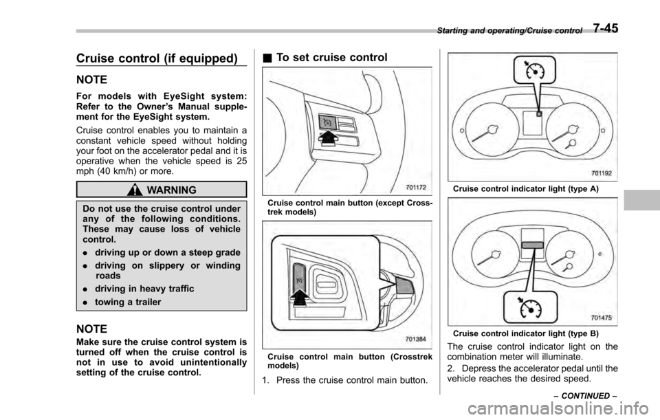
&To set cruise control
Cruise control main button (except Cross-
trek models)
Cruise control main button (Crosstrek
models)
1. Press the cruise control main button.
Cruise control indicator light (type A)
Cruise control indicator light (type B)
The cruise control indicator light on the
combination meter will illuminate.
2. Depress the accelerator pedal until the
vehicle reaches the desired speed.
Starting and operating/Cruise control
–CONTINUED –7-45
Page 438 of 594
.In the following cases, the BSD/
RCTA will temporarily stop operating
(or may stop operating) and the BSD/
RCTA warning indicator will appear.
–When the radar sensor becomes
significantly misaligned (If the or-
ientation of the radar sensor is
shifted for any reason, readjust-
ment is required. Have the sensor
adjusted at a SUBARU dealer.)
– When a large amount of snow or
ice sticks to the rear bumper sur-
face around the radar sensors
– When the vehicle is driven on a
snow-covered road or in an envir-
onment in which there are no
objects around (such as in a desert)
for a long time
– When the temperature around
the radar sensors increased exces-
sively due to long driving on uphill
grades in summer, etc.
– When the temperature around
the radar sensors becomes extre-
mely low
– When the vehicle battery voltage
lowers
– When the vehicle battery be-
comes overvoltage
When the above conditions are cor-
rected, the BSD/RCTA will resume operation and the BSD/RCTA warning
indicator will disappear. However, if the
BSD/RCTA warning indicator has ap-
peared for a prolonged time, have the
system inspected at a SUBARU dealer
as soon as possible.
.
The detectability of the radar sen-
sors is restricted. The BSD/RCTA de-
tection may be impaired and the sys-
tem may not operate properly under the
following conditions.
–When the rear bumper around
the radar sensors is distorted
– When ice, snow or mud adheres
to the rear bumper surface around
the radar sensors
– When stickers, etc. are affixed on
the areas of the radar sensors on
the rear bumper
– During adverse weather condi-
tions such as rain, snow or fog
– When driving on wet roads such
as snow-covered roads and
through puddles
. The radar sensors may not detect or
may have difficulty detecting the fol-
lowing.
–Small motorcycles, bicycles, pe-
destrians, stationary objects on the
road or road side, etc.
– Vehicles with body shapes that
the radar may not reflect (vehicles with a low body height such as
sports cars or a trailer with no
cargo)
–
Vehicles that are not approach-
ing your vehicle even though they
are in the detection area (either on a
neighboring lane to the rear or
beside your vehicle when rever-
sing) (The system determines the
presence of approaching vehicles
based on data detected by the radar
sensors.)
– Vehicles traveling at significantly
different speeds
– Vehicles driving in parallel at
almost the same speed as your
vehicle for a prolonged time
– Oncoming vehicles
– Vehicles in a lane beyond the
neighboring lane
– Vehicles travelling at a signifi-
cantly lower speed that you are
trying to overtake
. On a road with extremely narrow
lanes, the system may detect vehicles
driving in a lane next to the neighbor-
ing lane.
Starting and operating/BSD/RCTA (5 –door models —if equipped)
–CONTINUED –7-53
Page 442 of 594
nation meter, and the BSD/RCTA is
deactivated.
Press the switch again to activate the
BSD/RCTA. The BSD/RCTA OFF indica-
tor will disappear.
NOTE
.In the following cases, the system
may not operate properly due to
blocked radar waves. Press the BSD/
RCTA OFF switch to deactivate the
system.
–When towing a trailer
– When a bicycle carrier or other
item is fitted to the rear of the
vehicle
– When using a chassis dynam-
ometer or free roller device, etc.
– When running the engine and
makingthewheelsrotatewhile
lifting up the vehicle
. If the ignition switch is turned to the
“LOCK ”/“OFF ”position, the last known
status of the system is maintained. For
example, if the ignition switch is turned
to the “LOCK ”/“OFF ”position with the
BSD/RCTA deactivated, the BSD/RCTA
will remain deactivated the next time
the ignition switch is turned to the
“ON ”position.
. If the vehicle battery is disconnected
due to situations such as battery terminal or fuse replacement, after the
battery is reconnected, the BSD/RCTA
will be activated.
&
Certification for the BSD/
RCTA
FCC ID: OAYSRR2A
CAUTION
FCC WARNING
Changes or modifications not ex-
pressly approved by the party re-
sponsible for compliance could void
the user ’s authority to operate the
equipment.
This device complies with part 15 of the
FCC Rules. Operation is subject to the
following two conditions: (1) This device
may not cause harmful interference, and
(2) this device must accept any interfer-
ence received, including interference that
may cause undesired operation.
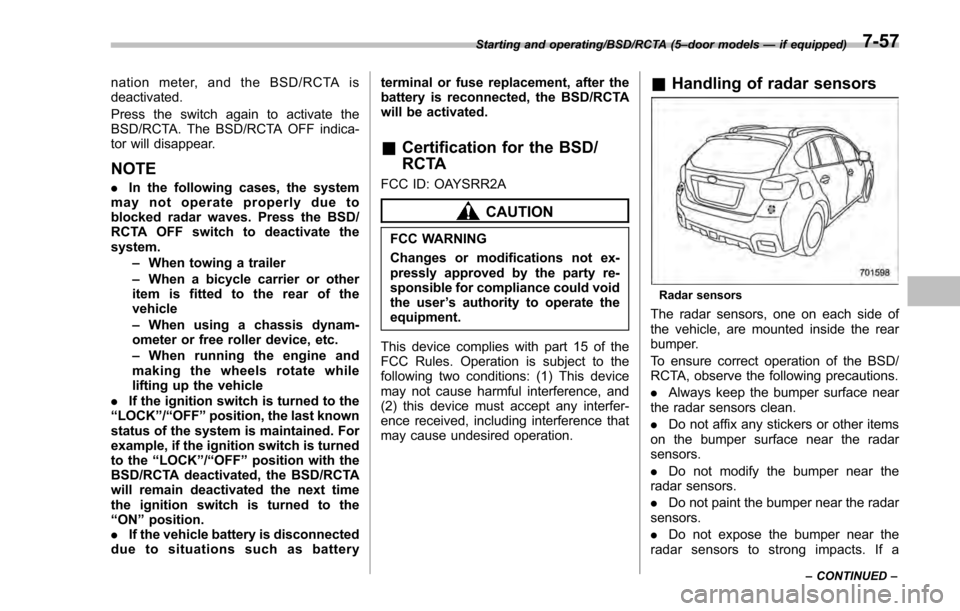
& Handling of radar sensors
Radar sensors
The radar sensors, one on each side of
the vehicle, are mounted inside the rear
bumper.
To ensure correct operation of the BSD/
RCTA, observe the following precautions.
. Always keep the bumper surface near
the radar sensors clean.
. Do not affix any stickers or other items
on the bumper surface near the radar
sensors.
. Do not modify the bumper near the
radar sensors.
. Do not paint the bumper near the radar
sensors.
. Do not expose the bumper near the
radar sensors to strong impacts. If a
Starting and operating/BSD/RCTA (5 –door models —if equipped)
–CONTINUED –7-57
Page 444 of 594
New vehicle break-in driving–the first
1,000 miles (1,600 km) ..................................... 8-2
Fuel economy hints ............................................ 8-2
Engine exhaust gas (carbon monoxide) ............ 8-2
Catalytic converter .............................................. 8-3
Periodic inspections ........................................... 8-4
Driving in foreign countries ............................... 8-4
Driving tips for AWD models .............................. 8-4
Off road driving ................................................... 8-6
Except Crosstrek models. .................................... 8-6
Crosstrek models ................................................ 8-6
Winter driving...................................................... 8-8Operation during cold weather ............................. 8-8
Driving on snowy and icy roads .......................... 8-9
Corrosion protection .......................................... 8-10
Snow tires ......................................................... 8-10
Tire chains ......................................................... 8-11
Rocking the vehicle ............................................ 8-11
Loading your vehicle ......................................... 8-12Vehicle capacity weight ...................................... 8-13
GVWR and GAWR (Gross Vehicle Weight Rating and Gross Axle Weight Rating) ........................ 8-13
Roof rail (if equipped) ........................................ 8-14
Roof molding and crossbar (5-door models —if
equipped) ........................................................ 8-15
Trailer hitch (Crosstrek models —dealer
option) ............................................................. 8-16
Connecting a trailer ........................................... 8-17
If not towing a trailer .......................................... 8-18
Trailer towing (Crosstrek models) .................... 8-18Warranties and maintenance.............................. 8-19
Maximum load limits .......................................... 8-19
Trailer Hitches ................................................... 8-22
Connecting a trailer ........................................... 8-23
Trailer towing tips .............................................. 8-24
Driving tips
8
Page 456 of 594
ious injury.
CAUTION
Do not carry spray cans, containers
with flammable or corrosive liquids
or any other dangerous items inside
the vehicle.
NOTE
For better fuel economy, do not carry
unneeded cargo.
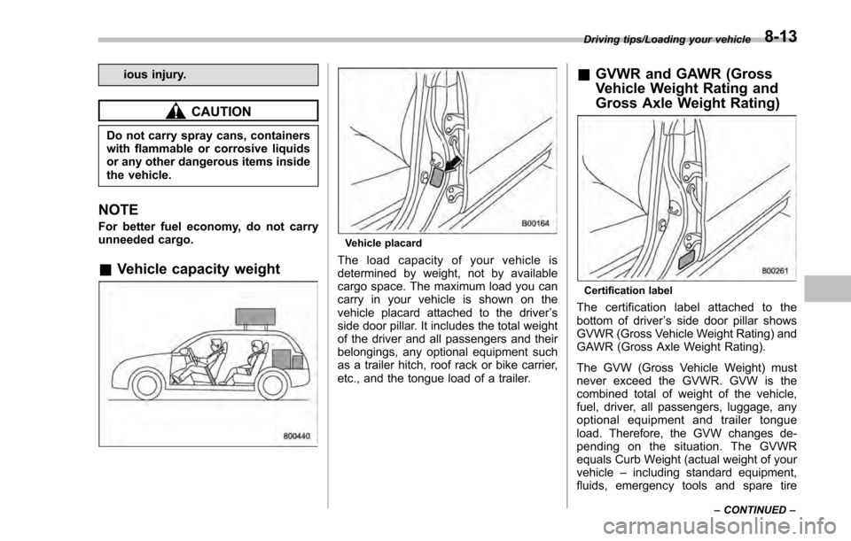
&Vehicle capacity weight
Vehicle placard
The load capacity of your vehicle is
determined by weight, not by available
cargo space. The maximum load you can
carry in your vehicle is shown on the
vehicle placard attached to the driver ’s
side door pillar. It includes the total weight
of the driver and all passengers and their
belongings, any optional equipment such
as a trailer hitch, roof rack or bike carrier,
etc., and the tongue load of a trailer.
& GVWR and GAWR (Gross
Vehicle Weight Rating and
Gross Axle Weight Rating)
Certification label
The certification label attached to the
bottom of driver ’s side door pillar shows
GVWR (Gross Vehicle Weight Rating) and
GAWR (Gross Axle Weight Rating).
The GVW (Gross Vehicle Weight) must
never exceed the GVWR. GVW is the
combined total of weight of the vehicle,
fuel, driver, all passengers, luggage, any
optional equipment and trailer tongue
load. Therefore, the GVW changes de-
pending on the situation. The GVWR
equals Curb Weight (actual weight of your
vehicle –including standard equipment,
fluids, emergency tools and spare tire
Driving tips/Loading your vehicle
–CONTINUED –8-13
Page 459 of 594
Driving tips/Trailer hitch (Crosstrek models—dealer option)
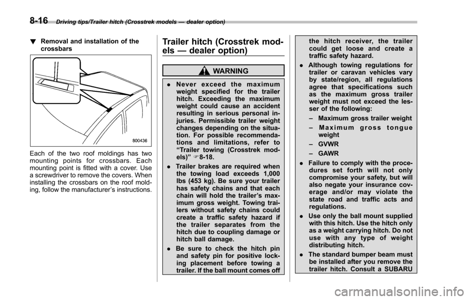
! Removal and installation of the
crossbars
Each of the two roof moldings has two
mounting points for crossbars. Each
mounting point is fitted with a cover. Use
a screwdriver to remove the covers. When
installing the crossbars on the roof mold-
ing, follow the manufacturer ’s instructions.
Trailer hitch (Crosstrek mod-
els —dealer option)
WARNING
. Never exceed the maximum
weight specified for the trailer
hitch. Exceeding the maximum
weight could cause an accident
resulting in serious personal in-
juries. Permissible trailer weight
changes depending on the situa-
tion. For possible recommenda-
tions and limitations, refer to
“Trailer towing (Crosstrek mod-
els) ”F 8-18.
. Trailer brakes are required when
the towing load exceeds 1,000
lbs (453 kg). Be sure your trailer
has safety chains and that each
chain will hold the trailer ’s max-
imum gross weight. Towing trai-
lers without safety chains could
create a traffic safety hazard if
the trailer separates from the
hitch due to coupling damage or
hitch ball damage.
. Be sure to check the hitch pin
and safety pin for positive lock-
ing placement before towing a
trailer. If the ball mount comes off the hitch receiver, the trailer
could get loose and create a
traffic safety hazard.
. Although towing regulations for
trailer or caravan vehicles vary
by state/region, all regulations
agree that specifications such
as the maximum gross trailer
weight must not exceed the les-
ser of the following:
– Maximum gross trailer weight
– Maximum gross tongue
weight
– GVWR
– GAWR
. Failure to comply with the proce-
dures set forth will not only
compromise your safety, but will
also negate your insurance cov-
erageand/ormayviolatethe
state road and traffic acts and
regulations.
. Use only the ball mount supplied
with this hitch. Use the hitch only
as a weight carrying hitch. Do not
use with any type of weight
distributing hitch.
. The standard bumper beam must
be installed after you remove the
trailer hitch. Consult a SUBARU
8-16