2016 SUBARU IMPREZA door lock
[x] Cancel search: door lockPage 147 of 594

Instruments and controls
Cruise control indicator light (if equipped).......... 3-31
Cruise control set indicator light (if equipped) ......................................................... 3-31
Automatic headlight beam leveler warning light (models with HID headlights) ............................ 3-31
Front fog light indicator light (if equipped) .......... 3-31
Headlight indicator light (if equipped) ................. 3-32
Steering responsive fog lights warning indicator/ Steering responsive fog lights OFF indicator
(models with EyeSight system) ......................... 3-32
BSD/RCTA warning indicator (if equipped) .......... 3-32
BSD/RCTA OFF indicator (if equipped) ................ 3-32
Information display (if equipped)...................... 3-32Outside temperature indicator............................ 3-33
Driving information display ................................. 3-33
Clock ................................................................. 3-37
Multi information display (models with type
B combination meter) ..................................... 3-38
Basic operation.................................................. 3-39
Welcome screen and Good-bye screen ............... 3-39
Warning screen .................................................. 3-40
Basic screens .................................................... 3-40
Menu screens .................................................... 3-40
Multi function display ........................................ 3-42Models without multi function display ................. 3-42
Safety precautions ............................................. 3-43
Features ............................................................ 3-43
Locations ........................................................... 3-43
Basic operation .................................................. 3-44
Welcome screen ................................................. 3-44
Date screen ........................................................ 3-44 Ending screen
................................................... 3-45
Self-check screen .............................................. 3-45
Interruption screen ............................................ 3-46
Basic screens .................................................... 3-47
Selection screen ................................................ 3-54
Date and time settings ....................................... 3-57
Image quality and volume settings ..................... 3-64
Screen settings. ................................................. 3-66
Maintenance settings ......................................... 3-74
Driving history registration ................................. 3-77
Car settings ....................................................... 3-78
Initialize ............................................................. 3-86
Light control switch ........................................... 3-89Precautions and tips .......................................... 3-89
Headlights ......................................................... 3-89
High/low beam change (dimmer) ... ..................... 3-91
Headlight flasher ............................................... 3-91
Daytime running light system ............................. 3-92
Turn signal lever................................................ 3-92One-touch lane changer ..................................... 3-93
Illumination brightness control ......................... 3-93
Headlight beam leveler (if equipped) ............... 3-94
Automatic headlight beam leveler (models with
HID headlights) ................................................ 3-94
Fog light switch (if equipped) ........................... 3-94Steering responsive fog lights system (models
with EyeSight system) ..................................... 3-95
Wiper and washer.............................................. 3-96Windshield wiper and washer switches .............. 3-97
Rear window wiper and washer switch –
5-door ............................................................. 3-99
Page 150 of 594
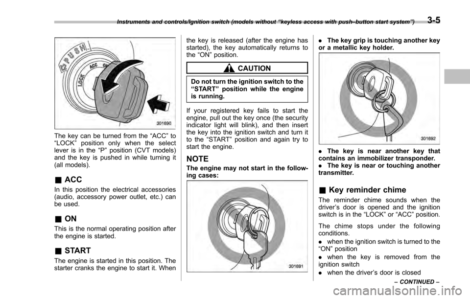
The key can be turned from the“ACC”to
“ LOCK ”position only when the select
lever is in the “P”position (CVT models)
and the key is pushed in while turning it
(all models).
& ACC
In this position the electrical accessories
(audio, accessory power outlet, etc.) can
be used.
&ON
This is the normal operating position after
the engine is started.
&START
The engine is started in this position. The
starter cranks the engine to start it. When the key is released (after the engine has
started), the key automatically returns to
the
“ON ”position.
CAUTION
Do not turn the ignition switch to the
“START ”position while the engine
is running.
If your registered key fails to start the
engine, pull out the key once (the security
indicator light will blink), and then insert
the key into the ignition switch and turn it
to the “START ”position and again try to
start the engine.
NOTE
The engine may not start in the follow-
ing cases:
. The key grip is touching another key
or a metallic key holder.
. The key is near another key that
contains an immobilizer transponder.
. The key is near or touching another
transmitter.
& Key reminder chime
The reminder chime sounds when the
driver ’s door is opened and the ignition
switch is in the “LOCK ”or “ACC ”position.
The chime stops under the following
conditions.
. when the ignition switch is turned to the
“ON ”position
. when the key is removed from the
ignition switch
. when the driver ’s door is closed
Instruments and controls/Ignition switch (models without “keyless access with push –button start system ”)
– CONTINUED –3-5
Page 151 of 594
Instruments and controls/Push–button ignition switch (models with push –button start system)
& Ignition switch light (if
equipped)
For easy access to the ignition switch in
the dark, the ignition switch light illumi-
nates when the driver ’s door is opened or
when the driver ’s door is unlocked using
the remote keyless entry transmitter.
The light remains illuminated for several
tens of seconds and then gradually turns
off under the following conditions.
. when the driver ’s door is closed
. when the doors are unlocked using the
remote keyless entry transmitter
The light turns off immediately under the
following conditions.
. when the ignition switch is turned to the
“ ON ”position
. when all doors and the rear gate (5-
door) are locked using the remote keyless
entry transmitter
Push-button ignition switch
(models with push-button
start system)
& Safety precautions
Refer to “Safety precautions” F2-10.
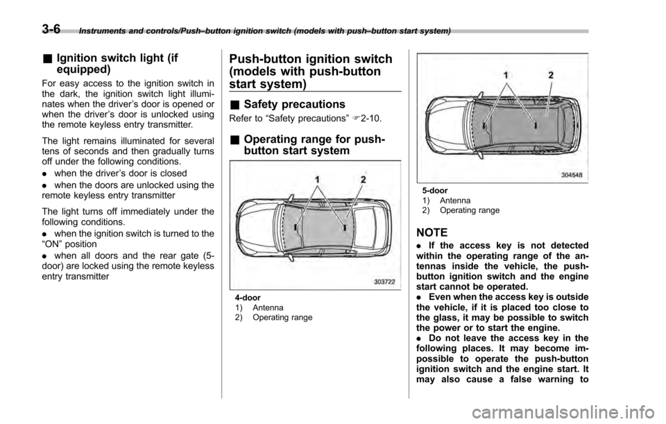
& Operating range for push-
button start system
4-door
1) Antenna
2) Operating range
5-door
1) Antenna
2) Operating range
NOTE
. If the access key is not detected
within the operating range of the an-
tennas inside the vehicle, the push-
button ignition switch and the engine
start cannot be operated.
. Even when the access key is outside
the vehicle, if it is placed too close to
the glass, it may be possible to switch
the power or to start the engine.
. Do not leave the access key in the
following places. It may become im-
possible to operate the push-button
ignition switch and the engine start. It
may also cause a false warning to
3-6
Page 155 of 594
Instruments and controls/Meters and gauges
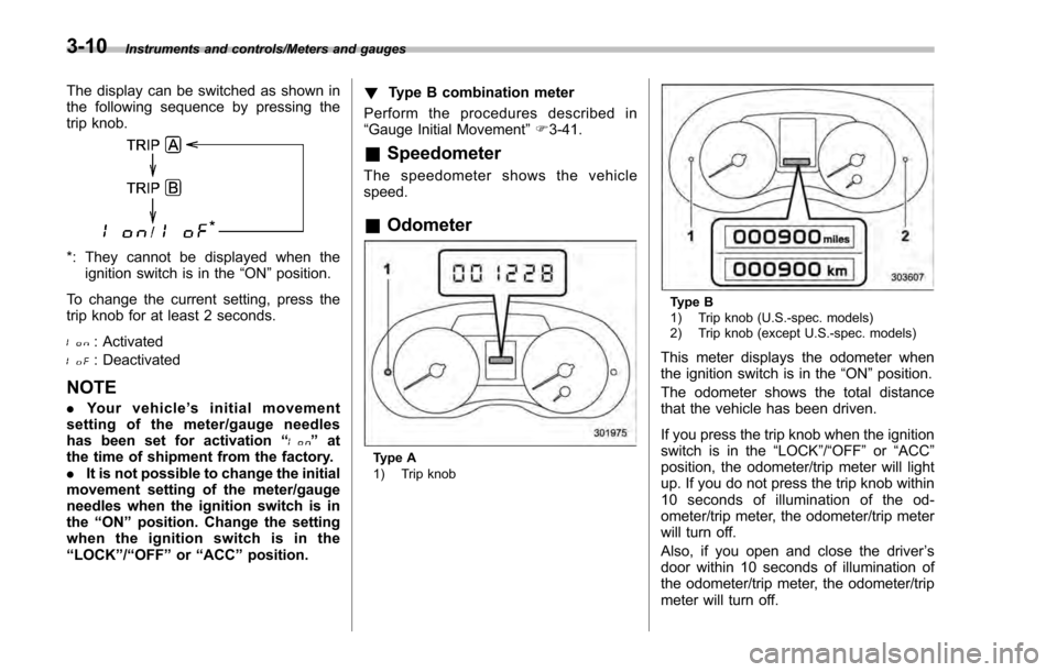
The display can be switched as shown in
the following sequence by pressing the
trip knob.
*: They cannot be displayed when theignition switch is in the “ON”position.
To change the current setting, press the
trip knob for at least 2 seconds.
: Activated
: Deactivated
NOTE
. Your vehicle ’s initial movement
setting of the meter/gauge needles
has been set for activation “
”at
the time of shipment from the factory.
. It is not possible to change the initial
movement setting of the meter/gauge
needles when the ignition switch is in
the “ON ”position. Change the setting
whentheignitionswitchisinthe
“LOCK ”/“OFF ”or “ACC ”position. !
Type B combination meter
Perform the procedures described in
“Gauge Initial Movement ”F 3-41.
& Speedometer
The speedometer shows the vehicle
speed.
&Odometer
Type A
1) Trip knob
Type B
1) Trip knob (U.S.-spec. models)
2) Trip knob (except U.S.-spec. models)
This meter displays the odometer when
the ignition switch is in the “ON”position.
The odometer shows the total distance
that the vehicle has been driven.
If you press the trip knob when the ignition
switch is in the “LOCK”/“ OFF ”or “ACC ”
position, the odometer/trip meter will light
up. If you do not press the trip knob within
10 seconds of illumination of the od-
ometer/trip meter, the odometer/trip meter
will turn off.
Also, if you open and close the driver ’s
door within 10 seconds of illumination of
the odometer/trip meter, the odometer/trip
meter will turn off.
3-10
Page 156 of 594
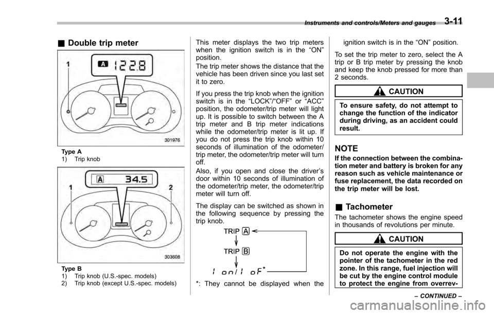
&Double trip meter
Type A
1) Trip knob
Type B
1) Trip knob (U.S.-spec. models)
2) Trip knob (except U.S.-spec. models)
This meter displays the two trip meters
when the ignition switch is in the “ON”
position.
The trip meter shows the distance that the
vehicle has been driven since you last set
it to zero.
If you press the trip knob when the ignition
switch is in the “LOCK”/ “OFF”or “ACC ”
position, the odometer/trip meter will light
up. It is possible to switch between the A
trip meter and B trip meter indications
while the odometer/trip meter is lit up. If
you do not press the trip knob within 10
seconds of illumination of the odometer/
trip meter, the odometer/trip meter will turn
off.
Also, if you open and close the driver ’s
door within 10 seconds of illumination of
the odometer/trip meter, the odometer/trip
meter will turn off.
The display can be switched as shown in
the following sequence by pressing the
trip knob.
*: They cannot be displayed when the ignition switch is in the
“ON ”position.
To set the trip meter to zero, select the A
trip or B trip meter by pressing the knob
and keep the knob pressed for more than
2 seconds.
CAUTION
To ensure safety, do not attempt to
change the function of the indicator
during driving, as an accident could
result.
NOTE
If the connection between the combina-
tion meter and battery is broken for any
reason such as vehicle maintenance or
fuse replacement, the data recorded on
the trip meter will be lost.
& Tachometer
The tachometer shows the engine speed
in thousands of revolutions per minute.
CAUTION
Do not operate the engine with the
pointer of the tachometer in the red
zone. In this range, fuel injection will
be cut by the engine control module
to protect the engine from overrev-
Instruments and controls/Meters and gauges
–CONTINUED –3-11
Page 157 of 594
Instruments and controls/Meters and gauges
ving. The engine will resume run-
ning normally after the engine speed
is reduced below the red zone.
NOTE
To protect the engine/transmission
while the select lever is in the“P ” or
“N ”position (for CVT models) or the
shift lever is in the neutral position (for
MT models), the engine is controlled so
that the engine speed may not become
too high even if the accelerator pedal is
pressed hard.
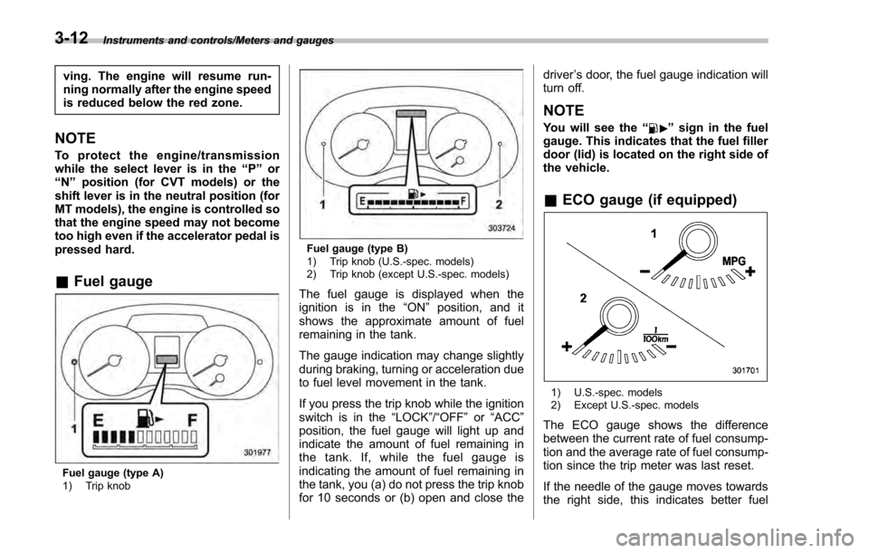
& Fuel gauge
Fuel gauge (type A)
1) Trip knob
Fuel gauge (type B)
1) Trip knob (U.S.-spec. models)
2) Trip knob (except U.S.-spec. models)
The fuel gauge is displayed when the
ignition is in the “ON”position, and it
shows the approximate amount of fuel
remaining in the tank.
The gauge indication may change slightly
during braking, turning or acceleration due
to fuel level movement in the tank.
If you press the trip knob while the ignition
switch is in the “LOCK”/ “OFF”or “ACC ”
position, the fuel gauge will light up and
indicate the amount of fuel remaining in
the tank. If, while the fuel gauge is
indicating the amount of fuel remaining in
the tank, you (a) do not press the trip knob
for 10 seconds or (b) open and close the driver
’s door, the fuel gauge indication will
turn off.
NOTE
You will see the “”sign in the fuel
gauge. This indicates that the fuel filler
door (lid) is located on the right side of
the vehicle.
& ECO gauge (if equipped)
1) U.S.-spec. models
2) Except U.S.-spec. models
The ECO gauge shows the difference
between the current rate of fuel consump-
tion and the average rate of fuel consump-
tion since the trip meter was last reset.
If the needle of the gauge moves towards
the right side, this indicates better fuel
3-12
Page 168 of 594
dealer.
! Hill start assist OFF indicator light
While the Hill start assist system is
deactivated, the Hill start assist OFF
indicator light illuminates continuously to
inform the driver that the Hill start assist
system is not operational.
&Door open warning
light
The warning light illuminates if any door,
the rear gate (5-door models) or trunk lid
(4-door models) is not fully closed. This
function is effective even if the ignition
switch is in the “LOCK”/ “OFF”or “ACC ”
position, or the key is removed from the
ignition switch.
Always make sure this light is not illumi-
nated before you start to drive.
&All-Wheel Drive warn-
ing light (CVT models)
This light blinks if the vehicle is driven with
tires of differing diameters fitted on the
wheels or with an excessively low air
pressure in any of the tires.
WARNING
If the AWD warning light flashes,
promptly park in a safe location then
check whether all four tires are the
same diameter and whether any of
the tires has a puncture or has lost
air pressure for some other reason.
Continuing to drive with the AWD
warning light flashing can lead to
powertrain damage.
&Power steering warn-
ing light
This warning light illuminates when the
ignition switch is turned to the “ON ”
position and turns off after the engine
has started. This indicates that the warn-
ing system is working properly.
While the engine is running, this warning
light illuminates when a malfunction has
been detected in the electric power steer-
ing system.
CAUTION
When the power steering warning
light is illuminated, there may be
more resistance when the steering
wheel is operated. Drive carefully to the nearest SUBARU dealer and
have the vehicle inspected immedi-
ately.
NOTE
If the steering wheel is operated in the
following ways, the power steering
control system may temporarily limit
the power assist in order to prevent the
system components, such as the con-
trol computer and drive motor, from
overheating.
.
The steering wheel is operated fre-
quently and turned sharply while the
vehicle is maneuvered at extremely low
speeds, such as while frequently turn-
ing the steering wheel during parallel
parking.
. The steering wheel remains in the
fully turned position for a long period
of time.
At this time, there will be more resis-
tance when steering. However this is
not a malfunction. Normal steering
force will be restored after the steering
wheel is not operated for a while and
the power steering control system has
an opportunity to cool down. However,
if the power steering is operated in a
non-standard way which causes power
assist limitation to occur too fre-
Instruments and controls/Warning and indicator lights
–CONTINUED –3-23
Page 171 of 594

Instruments and controls/Warning and indicator lights
accident involving serious injury or
death.
CAUTION
.When starting the engine again
after the operation indicator on
the push-button ignition switch
flashes in green, if the operation
indicator is still flashing in green,
there could be a steering lock
malfunction. Contact your
SUBARU dealer as soon as pos-
sible.
. When the operation indicator on
the push-button ignition switch
flashes in orange, contact a
SUBARU dealer immediately.
NOTE
. When doors are not locked because
the access key is left inside the trunk,
you cannot open the trunk lid by
pushing the trunk opener button on
the trunk lid. Pull the trunk lid release
lever upward to open the trunk lid.
Refer to “To open the trunk lid from
inside” F2-39.
. Do not leave the access key inside
the trunk. Depending on the status of
the access key and situation, the trunk
lockout protect function may not oper-
ate. Make sure that you carry the
access key, and close the trunk lid.
. Even when the access key is within
the operating ranges inside the vehicle,
the access key warning for engine start
may be provided depending on the
status of the access key and the
environmental conditions.
. When the access key is taken out of
the vehicle through an open window,
the access key takeout warning or
passenger access key takeout warning
will not be provided. !
List of warnings
CAUTION
When any of the following warnings
occurs even if the access key warn-
ing indicator does not appear, take
the appropriate action.
3-26