2016 SUBARU IMPREZA parking brake
[x] Cancel search: parking brakePage 485 of 594
In case of emergency/Towing
the vehicle and stow it in the tool bucket.
Fit the towing hook cover on the bumper.
WARNING
.Do not use the towing hook
except when towing your vehicle.
. Be sure to remove the towing
hook after towing. Leaving the
towing hook mounted on the
vehicle could interfere with prop-
er operation of the fuel pump
shut off function when the vehi-
cle is struck from behind.
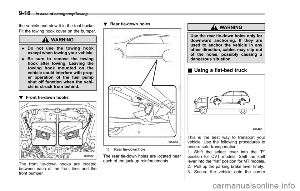
! Front tie-down hooks
The front tie-down hooks are located
between each of the front tires and the
front bumper. !
Rear tie-down holes
1) Rear tie-down hole
The rear tie-down holes are located near
each of the jack-up reinforcements.
WARNING
Use the rear tie-down holes only for
downward anchoring. If they are
used to anchor the vehicle in any
other direction, cables may slip out
of the holes, possibly causing a
dangerous situation.
&Using a flat-bed truck
This is the best way to transport your
vehicle. Use the following procedures to
ensure safe transportation.
1. Shift the select lever into the “P ”
position for CVT models. Shift the shift
lever into the “1st”position for MT models.
2. Pull up the parking brake lever firmly.
3. Secure the vehicle onto the carrier
9-16
Page 486 of 594
properly with safety chains. Each safety
chain should be equally tightened and
care must be taken not to pull the chains
so tightly that the suspension bottoms out.
CAUTION
If your vehicle has a front under-
spoiler and rear underspoiler (both
optional), be careful not to scrape
them when placing the vehicle on
the carrier and when removing the
vehicle from the carrier.
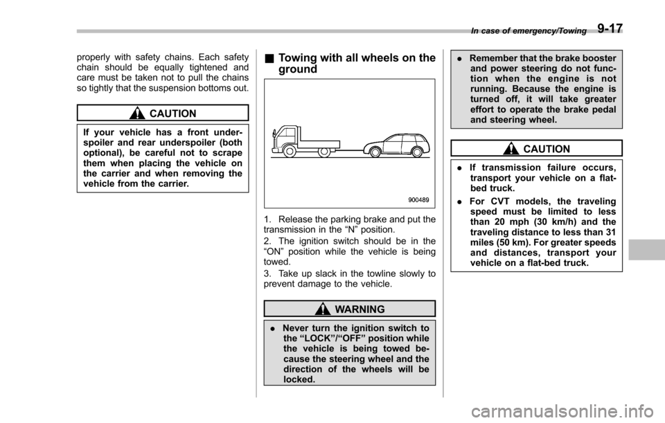
&Towing with all wheels on the
ground
1. Release the parking brake and put the
transmission in the “N”position.
2. The ignition switch should be in the
“ON ”position while the vehicle is being
towed.
3. Take up slack in the towline slowly to
prevent damage to the vehicle.
WARNING
. Never turn the ignition switch to
the “LOCK ”/“OFF ”position while
the vehicle is being towed be-
cause the steering wheel and the
direction of the wheels will be
locked. .
Remember that the brake booster
and power steering do not func-
tion when the engine is not
running. Because the engine is
turned off, it will take greater
effort to operate the brake pedal
and steering wheel.
CAUTION
. If transmission failure occurs,
transport your vehicle on a flat-
bed truck.
. For CVT models, the traveling
speed must be limited to less
than 20 mph (30 km/h) and the
traveling distance to less than 31
miles (50 km). For greater speeds
and distances, transport your
vehicle on a flat-bed truck.
In case of emergency/Towing9-17
Page 487 of 594
In case of emergency/Access key–if access key does not operate properly
Access key –if access key
does not operate properly
CAUTION
Keep metallic objects, magnetic
sources and signal transmitters
away from the area between the
access key and the push-button
ignition switch. They may interfere
with the communication between
the access key and the push-button
ignition switch.
If the locking/unlocking procedures, power
switch procedures or engine start proce-
dures cannot be operated because of
strong radio signals in the surrounding
area or a low battery condition of the
access key, perform the following proce-
dure. When the battery of the access key
is discharged, replace it with a new one.
Refer to “Replacing battery of access key ”
F 11-44.
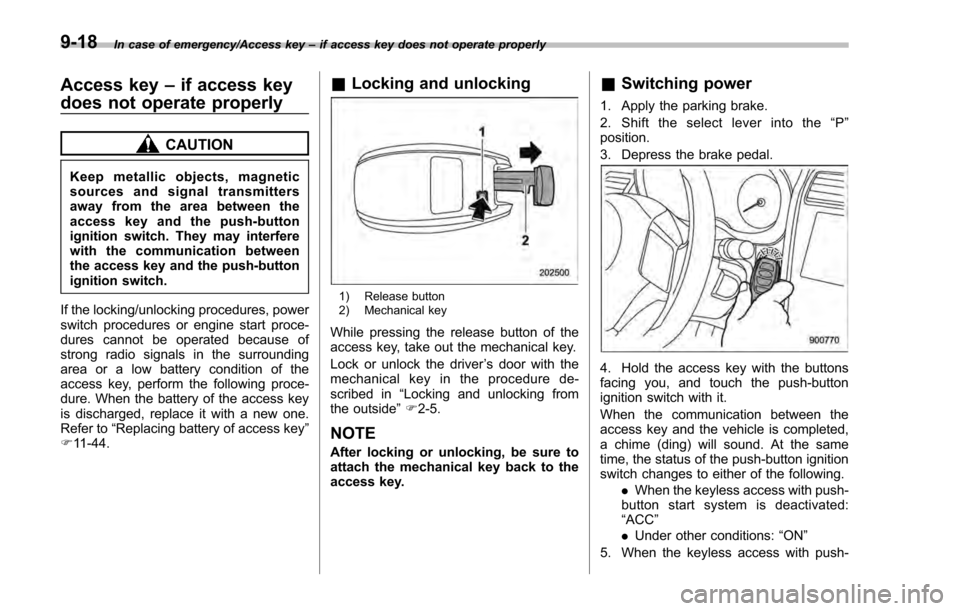
& Locking and unlocking
1) Release button
2) Mechanical key
While pressing the release button of the
access key, take out the mechanical key.
Lock or unlock the driver ’s door with the
mechanical key in the procedure de-
scribed in “Locking and unlocking from
the outside ”F 2-5.
NOTE
After locking or unlocking, be sure to
attach the mechanical key back to the
access key.
& Switching power
1. Apply the parking brake.
2. Shift the select lever into the “P ”
position.
3. Depress the brake pedal.
4. Hold the access key with the buttons
facing you, and touch the push-button
ignition switch with it.
When the communication between the
access key and the vehicle is completed,
a chime (ding) will sound. At the same
time, the status of the push-button ignition
switch changes to either of the following.
.When the keyless access with push-
button start system is deactivated:
“ACC ”
. Under other conditions: “ON ”
5. When the keyless access with push-
9-18
Page 488 of 594
button start system is deactivated, press
the push-button ignition switch with the
brake pedal released. The status of the
push-button ignition switch then changes
to“ON ”.
NOTE
If the power does not switch even
though the above procedure was fol-
lowed precisely, contact your SUBARU
dealer.
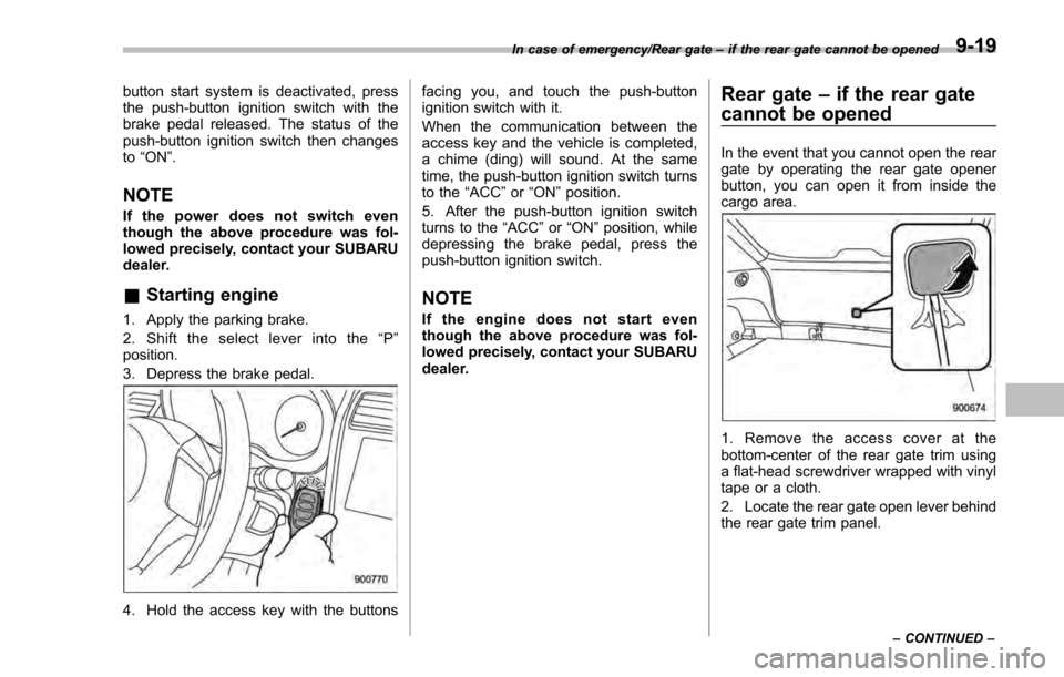
&Starting engine
1. Apply the parking brake.
2. Shift the select lever into the “P ”
position.
3. Depress the brake pedal.
4. Hold the access key with the buttons facing you, and touch the push-button
ignition switch with it.
When the communication between the
access key and the vehicle is completed,
a chime (ding) will sound. At the same
time, the push-button ignition switch turns
to the
“ACC”or “ON ”position.
5. After the push-button ignition switch
turns to the “ACC ”or “ON ”position, while
depressing the brake pedal, press the
push-button ignition switch.
NOTE
If the engine does not start even
though the above procedure was fol-
lowed precisely, contact your SUBARU
dealer.
Rear gate –if the rear gate
cannot be opened
In the event that you cannot open the rear
gate by operating the rear gate opener
button, you can open it from inside the
cargo area.
1. Remove the access cover at the
bottom-center of the rear gate trim using
a flat-head screwdriver wrapped with vinyl
tape or a cloth.
2. Locate the rear gate open lever behind
the rear gate trim panel.
In case of emergency/Rear gate –if the rear gate cannot be opened
–CONTINUED –9-19
Page 496 of 594

Maintenance schedule....................................... 11-3
Maintenance precautions ................................... 11-3
Before checking or servicing in the engine
compartment .................................................... 11-4
When checking or servicing in the engine compartment .................................................... 11-4
When checking or servicing in the engine compartment while the engine is running .......... 11-5
Engine hood....................................................... 11-5
Engine compartment overview .......................... 11-7
Engine oil ............................................................ 11-8
Engine oil consumption ...................................... 11-8
Locations of the oil level gauge, oil filler cap and oil filter ............................................................ 11-8
Checking the oil level ......................................... 11-8
Changing the oil and oil filter .............................. 11-9
Recommended grade and viscosity .................. 11-10
Synthetic oil ..................................................... 11-10
Cooling system ................................................ 11-10Safety precautions ........................................... 11-10
Cooling fan, hose and connections ................... 11-11
Engine coolant ................................................. 11-11
Air cleaner element .......................................... 11-12Replacing the air cleaner element ..................... 11-13
Spark plugs...................................................... 11-14Recommended spark plugs .............................. 11-14
Drive belts........................................................ 11-14
Manual transmission oil .................................. 11-14
Recommended grade and viscosity .................. 11-14
Continuously variable transmission fluid ....... 11-15Front differential gear oil (CVT models)
......... 11-15
Recommended grade and viscosity.................. 11-15
Rear differential gear oil.................................. 11-15Recommended grade and viscosity .................. 11-15
Brake fluid........................................................ 11-16Checking the fluid level .................................... 11-16
Recommended brake fluid ............................... 11-16
Clutch fluid (MT models)................................. 11-17Checking the fluid level.................................... 11-17
Recommended clutch fluid ............................... 11-17
Brake booster.................................................. 11-18
Brake pedal ...................................................... 11-18
Checking the brake pedal free play .................. 11-18
Checking the brake pedal reserve distance ....... 11-18
Clutch pedal (MT models) ............................... 11-19Checking the clutch function ............................ 11-19
Checking the clutch pedal free play .................. 11-19
Hill start assist system.................................... 11-19
Replacement of brake pad and lining ............ 11-20
Breaking-in of new brake pads and linings ....... 11-20
Parking brake stroke ....................................... 11-21
Tires and wheels .............................................. 11-21
Types of tires................................................... 11-21
Tire pressure monitoring system (TPMS) (if equipped) ...................................................... 11-21
Tire inspection ................................................. 11-23
Tire pressures and wear .................................. 11-23
Wheel balance ................................................. 11-25
Wear indicators ............................................... 11-25
Tire rotation direction mark .............................. 11-26
Maintenance and service
11
Page 499 of 594
Maintenance and service/Maintenance precautions
erative. NEVER use a circuit
tester for this wiring. If your
SRS airbag or seatbelt preten-
sioner needs service, consult
your nearest SUBARU dealer.
NOTE
SUBARU does not endorse the use of
non-SUBARU approved flushing sys-
tems and strongly advises against
performing these services on a
SUBARU vehicle. Non-SUBARU ap-
proved flushing systems use chemi-
cals and/or solvents which have not
been tested or approved by SUBARU.
SUBARU warranties do not cover any
part of the vehicle which is damaged by
adding or applying chemicals and/or
solvents other than those approved or
recommended by SUBARU.
&Before checking or servicing
in the engine compartment
WARNING
. Always stop the engine and apply
the parking brake firmly to pre-
vent the vehicle from moving.
. Always let the engine cool down.
Engine parts become very hot when the engine is running and
remain hot for some time after
the engine has stopped.
. Do not spill engine oil, engine
coolant, brake fluid or any other
fluid on hot engine components.
This may cause a fire.
. When the ignition switch is in the
“ON ”position, the cooling fan
may operate suddenly even
when the engine is stopped. If
your body or clothes come into
contact with a rotating fan, that
could result in serious injury. To
avoid risk of injury, perform the
following precautions.
– Models with push-button start
system:
Always turn the push-button
ignition switch to the “OFF”
position and confirm that the
operation indicator on the
switch is turned off. Then take
the access key out from the
vehicle.
– Models without push-button
start system:
Always remove the key from
the ignition switch.
. Before performing any servicing
on a vehicle equipped with a remote engine start system (a
dealer option), temporarily place
the remote engine start system in
service mode to prevent it from
unexpectedly starting the engine.
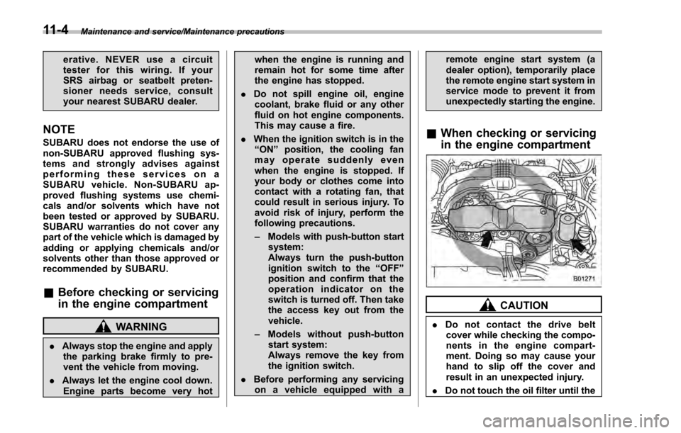
&
When checking or servicing
in the engine compartment
CAUTION
. Do not contact the drive belt
cover while checking the compo-
nents in the engine compart-
ment. Doing so may cause your
hand to slip off the cover and
result in an unexpected injury.
. Do not touch the oil filter until the
11-4
Page 515 of 594
Maintenance and service/Replacement of brake pad and lining
Replacement of brake pad
and lining
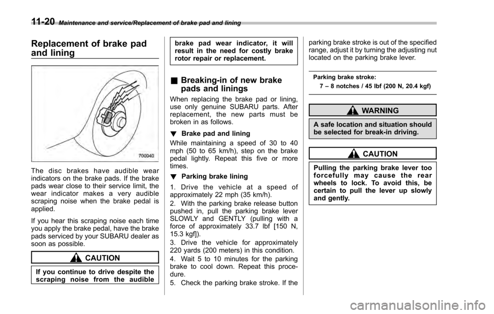
The disc brakes have audible wear
indicators on the brake pads. If the brake
pads wear close to their service limit, the
wear indicator makes a very audible
scraping noise when the brake pedal is
applied.
If you hear this scraping noise each time
you apply the brake pedal, have the brake
pads serviced by your SUBARU dealer as
soon as possible.
CAUTION
If you continue to drive despite the
scraping noise from the audiblebrake pad wear indicator, it will
result in the need for costly brake
rotor repair or replacement.
&
Breaking-in of new brake
pads and linings
When replacing the brake pad or lining,
use only genuine SUBARU parts. After
replacement, the new parts must be
broken in as follows.
! Brake pad and lining
While maintaining a speed of 30 to 40
mph (50 to 65 km/h), step on the brake
pedal lightly. Repeat this five or more
times.
! Parking brake lining
1. Drive the vehicle at a speed of
approximately 22 mph (35 km/h).
2. With the parking brake release button
pushed in, pull the parking brake lever
SLOWLY and GENTLY (pulling with a
force of approximately 33.7 lbf [150 N,
15.3 kgf]).
3. Drive the vehicle for approximately
220 yards (200 meters) in this condition.
4. Wait 5 to 10 minutes for the parking
brake to cool down. Repeat this proce-
dure.
5. Check the parking brake stroke. If the parking brake stroke is out of the specified
range, adjust it by turning the adjusting nut
located on the parking brake lever.
Parking brake stroke:
7–8 notches / 45 lbf (200 N, 20.4 kgf)
WARNING
A safe location and situation should
be selected for break-in driving.
CAUTION
Pulling the parking brake lever too
forcefully may cause the rear
wheels to lock. To avoid this, be
certain to pull the lever up slowly
and gently.
11-20
Page 516 of 594

Parking brake stroke
Check the parking brake stroke according
to the maintenance schedule in the
“Warranty and Maintenance Booklet ”.
When the parking brake is properly
adjusted, braking power is fully applied
by pulling the lever up 7 to 8 notches
gently but firmly (approximately 45 lbf [200
N, 20.4 kgf]). If the parking brake lever
stroke is not within the specified range,
have the brake system checked and
adjusted at your SUBARU dealer.
Tires and wheels
& Types of tires
You should be familiar with type of tires
present on your vehicle.
! All season tires
All season tires are designed to provide
an adequate measure of traction, handling
and braking performance in year-round
driving including snowy and icy road
conditions. However all season tires do
not offer as much traction performance as
winter (snow) tires in heavy or loose snow
or on icy roads.
All season tires are identified by “ALL
SEASON ”and/or “M+S ”(Mud & Snow) on
the tire sidewall.
! Summer tires
Summer tires are high-speed capability
tires best suited for highway driving under
dry conditions.
Summer tires are inadequate for driving
on slippery roads such as on snow-
covered or icy roads.
If you drive your vehicle on snow-covered
or icy roads, we strongly recommend the
use of winter (snow) tires.
When installing winter tires, be sure to
replace all four tires. !
Winter (snow) tires
Winter tires are best suited for driving on
snow-covered and icy roads. However
winter tires do not perform as well as
summer tires and all season tires on roads
other than snow-covered and icy roads.
& Tire pressure monitoring
system (TPMS) (if equipped)
The tire pressure monitoring system pro-
vides the driver with a warning message
by sending a signal from a sensor that is
installed in each wheel when tire pressure
is severely low. The tire pressure monitor-
ing system will activate only when the
vehicle is driven. Also, this system may
not react immediately to a sudden drop in
tire pressure (for example, a blow-out
caused by running over a sharp object).
If you adjust the tire pressures in a warm
garage and will then drive the vehicle in
cold outside air, the resulting drop in tire
pressures may cause the low tire pressure
warning light to illuminate. To avoid this
problem when adjusting the tire pressures
in a warm garage, inflate the tires to
pressures higher than those shown on the
tire placard. Specifically, inflate them by an
extra 1 psi (6.9 kPa, 0.07 kgf/cm
2) for
every difference of 10 8F (5.6 8C) between
the temperature in the garage and the
Maintenance and service/Parking brake stroke
–CONTINUED –11-21