2016 SUBARU IMPREZA engine
[x] Cancel search: enginePage 111 of 594
Keys and doors/Keyless access with push–button start system
. Opening the trunk (4-door)
. Starting and stopping the engine. For
detailed information, refer to “Starting and
stopping engine (models with push-button
start system) ”F 7-12.
. Arming and disarming the alarm sys-
tem. For detailed information, refer to
“ Alarm system ”F 2-27.
Locking and unlocking by the remote
keyless entry system can also be con-
trolled with the buttons on the access key.
For detailed information, refer to “Remote
keyless entry system ”F 2-23.
A mechanical key is attached to each
access key. The mechanical key is used
for the following operations.
. Locking and unlocking the driver ’s door
. Locking and unlocking the glove box
You cannot unlock the glove box without
using the mechanical key. You can keep
the glove box locked when you leave your
vehicle and the access key (with the
mechanical key removed) at a parking
facility.
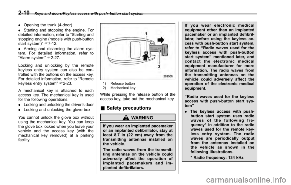
1) Release button
2) Mechanical key
While pressing the release button of the
access key, take out the mechanical key.
& Safety precautions
WARNING
If you wear an implanted pacemaker
or an implanted defibrillator, stay at
least 8.7 in (22 cm) away from the
transmitting antennas installed on
the vehicle.
The radio waves from the transmit-
ting antennas on the vehicle could
adversely affect the operation of
implanted pacemakers and im-
planted defibrillators. If you wear electronic medical
equipment other than an implanted
pacemaker or an implanted defibril-
lator, before using the keyless ac-
cess with push-button start system,
refer to
“Radio waves used for the
keyless access with push-button
start system ”mentioned later, and
contact the electronic medical
equipment manufacturer for more
information. The radio waves from
the transmitting antennas on the
vehicle could adversely affect the
operation of the electronic medical
equipment.
“Radio waves used for the keyless
access with push-button start sys-
tem ”
. The keyless access with push-
button start system uses radio
waves of the following fre-
quency* in addition to the radio
waves used for the remote key-
less entry system. The radio
waves are periodically output
from the antennas installed on
the vehicle as shown in the
following illustrations.
* Radio frequency: 134 kHz
2-10
Page 113 of 594

Keys and doors/Keyless access with push–button start system
– Do not wash the access key in
an ultrasonic washer.
– Do not leave the access key in
humid or dusty locations.
Doing so may cause malfunc-
tions.
– Do not leave the access key
near personal computers or
home electric appliances.
Doing so may cause the ac-
cess key to malfunction, re-
sulting in battery discharge.
. If the access key is dropped, the
integrated mechanical key inside
may become loose. Be careful
not to lose the mechanical key.
. When you carry the access key
on an airplane, do not press the
button of the access key while in
the airplane. When any button of
the access key is pressed, radio
waves are sent and may affect
the operation of the airplane.
When you carry the access key
in a bag on an airplane, take
measures to prevent the buttons
of the access key from being
pressed.NOTE
. The operational/non-operational
setting for the keyless access function
can be changed. For the setting proce-
dure, refer to “Disabling keyless ac-
cess function” F2-18. The setting can
also be changed by a SUBARU dealer.
For more details, contact a SUBARU
dealer.
. For detailed information about the
operation method for the push-button
ignition switch while the keyless ac-
cess function is switched to the non-
operational mode, refer to “Access key
– if access key does not operate
properly ”F 9-18.
. The keyless access with push-but-
ton start system uses weak radio
waves. The status of the access key
and environmental conditions may in-
terfere with the communication be-
tween the access key and the vehicle
under the following conditions, and it
may not be possible to lock or unlock
the doors or start the engine.
–When operating near a facility
where strong radio waves are trans-
mitted, such as a broadcast station
and power transmission lines
– When products that transmit
radio waves are used, such as an
access key or a remote transmitter key of another vehicle
–
When carrying more than one
access key
– When the access key is placed
near wireless communication
equipment such as a cell phone
– When the access key is placed
near a metallic object
– When metallic accessories are
attached to the access key
– When carrying the access key
with electronic appliances such as
a laptop computer
– When the battery of the access
key is discharged
. The access key is always commu-
nicating with the vehicle and is con-
tinuously using the battery. Although
the life of the battery varies depending
on the operating conditions, it is ap-
proximately 1 to 2 years. If the battery
becomes fully discharged, replace it
with a new one.
. If an access key is lost, it is
recommended that all of the remaining
access keys be reregistered. For rere-
gistration of an access key, contact a
SUBARU dealer.
. For a spare access key, contact a
SUBARU dealer.
. Up to 7 access keys can be regis-
tered for one vehicle.
2-12
Page 114 of 594
.Carefully store the key number plate
supplied with the access key. It is
necessary for vehicle repair.
. Do not leave the access key in the
storage spaces inside the vehicle, such
as the door pocket, dashboard and the
corner of the cargo area. Vibrations
may damage the key or turn on the
switch, possibly resulting in a lockout.
. After the vehicle battery is dis-
charged or replaced, initialization of
the steering lock system may be re-
quired to start the engine. In this case,
perform the following procedure to
initialize the steering lock.
(1) Turn the push-button ignition
switch to the “OFF”position. For
details, refer to “Switching power ”
F 3-7.
(2) Open and close the driver ’s
door.
(3) Wait for approximately 10 sec-
onds.
When the steering is locked, the initi-
alization is completed.
. Do not leave the access key in the
following places.
–On the instrument panel
– On the floor
– Inside the glove box
– Inside the door trim pocket –
On the rear seat
– On the rear shelf (4-door)
– Inside the trunk (4-door)
– In the cargo area (5-door)
If you do, the following situations
may occur. – The access key is mistakenly
locked inside the vehicle.
– A false warning issues although
no malfunction actually occurs.
– No warning issues even when
any malfunction occurs.& Locking and unlocking with
“keyless access ”entry func-
tion
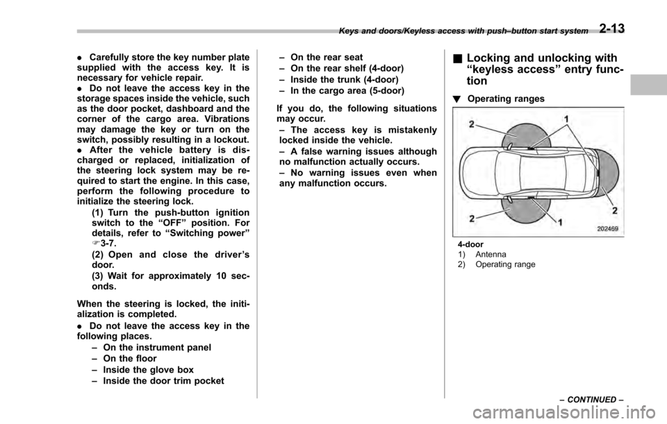
! Operating ranges
4-door
1) Antenna
2) Operating range
Keys and doors/Keyless access with push
–button start system
–CONTINUED –
2-13
Page 119 of 594
Keys and doors/Keyless access with push–button start system
dealer.
NOTE
The setting can be changed by your
SUBARU dealer. Contact your SUBARU
dealer for details. Also, for models with
the multi function display, the setting
can be changed by operating the multi
function display. For details, refer to
“Keyless access setting (models with
“keyless access with push-button start
system ”)”F3-84.
& Selecting audible signal op-
eration
Using an electronic chirp, the system will
give you an audible signal when the doors
lock and unlock. If desired, you may turn
the audible signal off. For more details,
contact a SUBARU dealer.
NOTE
For models with the multi function
display, the setting can be changed by
operating the multi function display.
For details, refer to “Keyless buzzer
volume setting ”F 3-79.
& Warning chimes and warning
indicator
The keyless access with push-button start
system sounds a warning chime and
flashes the access key warning indicator
on the combination meter in order to
minimize improper operations and help
protect your vehicle from theft.
For details, refer to “Warning chimes and
warning indicator of the keyless access
with push-button start system ”F 3-25.
& Disabling keyless access
function
WARNING
If you wear an implanted pacemaker
or an implanted defibrillator, per-
form the procedure described in
“By operating the driver ’s door ”
F 2-19 to disable the keyless access
function. If you perform the proce-
dure described in “By operating the
access key ”F 2-18, the operation of
an implanted pacemaker or im-
planted defibrillator may be affected
by the radio waves from the trans-
mitter antenna.
When the vehicle is not going to be used
for a long time, or when you choose not to use the keyless access function, the
keyless access function can be disabled.
NOTE
.
The locking and unlocking function
by the remote keyless entry system is
not disabled.
. The setting can also be changed at
SUBARU dealers. For more details,
contact a SUBARU dealer.
. To start the engine while the func-
tions are disabled, perform the proce-
dure described in “Starting engine”
F 9-19.
. We recommend that you disable the
keyless access functions under the
following conditions.
–When the vehicle is not going to
be used for an extended period of
time
– When the keyless access func-
tions are not going to be used
! Disabling functions
! By operating the access key
If you have registered a PIN code for PIN
Code Access, you can disable the keyless
access function by operating the access
key. For details about registering a PIN
code, refer to “Registering a PIN code”
F 2-22.
1. Open the driver ’s door.
2-18
Page 130 of 594
.Turn the push-button ignition to the
“ ACC ”position (models with “keyless
access with push-button start system ”).
NOTE
Only registered keys will stop the
alarm. If the immobilizer transponder
is not registered, the alarm will not
stop.
& Arming the system
! Tips
. The system can be armed even if the
engine hood, windows and/or moonroof
are open. Always make sure that they are
fully closed before arming the system.
. The 30-second standby time can be
eliminated if you prefer. Have it performed
by your SUBARU dealer.
. If your vehicle is a 4-door and you open
the trunk using the access key/remote
transmitter ’s “
”button with the alarm
system armed, the system will be tem-
porarily placed in a standby state. The
system will go back to the surveillance
state upon locking the trunk.
. The system is in the standby mode for
a 30-second period after locking the doors
with the remote transmitter. The security
indicator light will flash at short intervals
during this period. .
If any of the following actions are done
during the standby period, the system will
not switch to the surveillance state.
–Doors (including the rear gate/trunk
lid) are unlocked using the access key/
remote transmitter.
– Doors (including the rear gate/trunk
lid) are unlocked using the keyless
access function (models with “keyless
access with push-button start sys-
tem”).
– Any door (including the rear gate/
trunk lid) is opened.
– The ignition switch is turned to the
“ON ”position (models without “keyless
access with push-button start sys-
tem”).
– Push-button ignition switch is
turned to the “ACC”position (models
with “keyless access with push-button
start system ”).
! To arm the system using access
key/remote transmitter
1. Close all windows and the moonroof (if
equipped).
2. Remove the key from the ignition
switch (models without “keyless access
with push-button start system ”)/turn the
push-button ignition switch to the “OFF”
position (models with “keyless access with
push-button start system ”). 3. Open the doors and get out of the
vehicle.
4. Make sure that the engine hood (and
the trunk lid on the 4-door) are locked.
5. Close all doors (and the rear gate on
the 5-door).
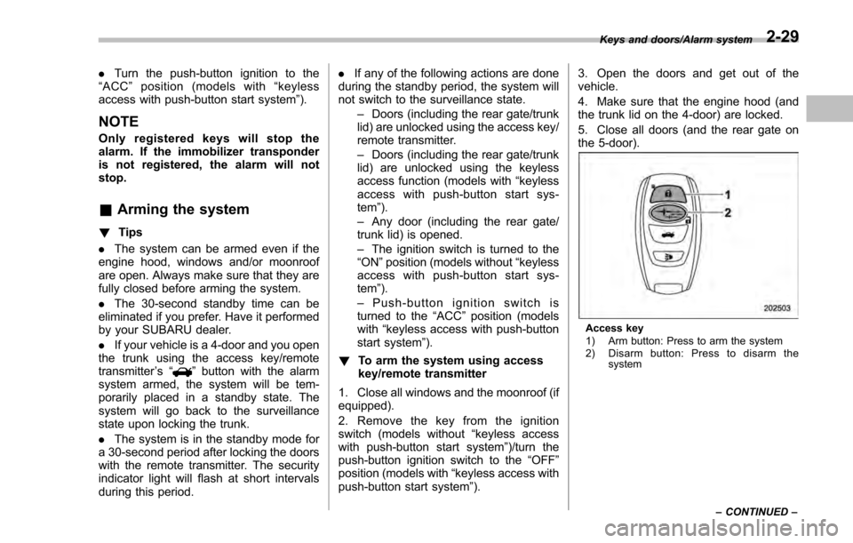
Access key
1) Arm button: Press to arm the system
2) Disarm button: Press to disarm the
system
Keys and doors/Alarm system
–CONTINUED –
2-29
Page 131 of 594
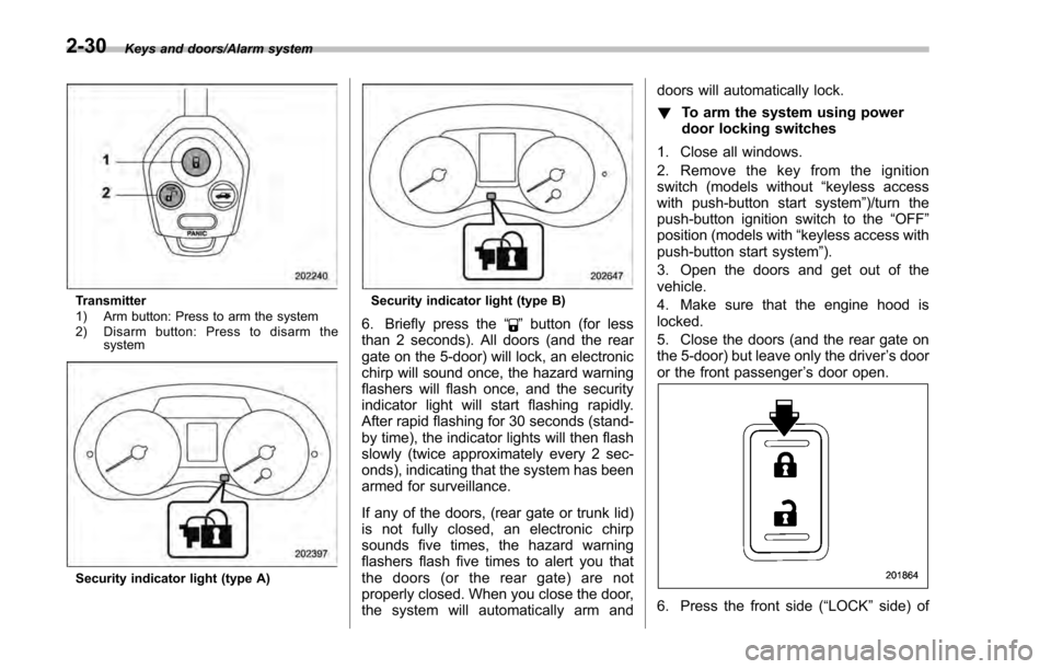
Keys and doors/Alarm system
Transmitter
1) Arm button: Press to arm the system
2) Disarm button: Press to disarm thesystem
Security indicator light (type A)
Security indicator light (type B)
6. Briefly press the “”button (for less
than 2 seconds). All doors (and the rear
gate on the 5-door) will lock, an electronic
chirp will sound once, the hazard warning
flashers will flash once, and the security
indicator light will start flashing rapidly.
After rapid flashing for 30 seconds (stand-
by time), the indicator lights will then flash
slowly (twice approximately every 2 sec-
onds), indicating that the system has been
armed for surveillance.
If any of the doors, (rear gate or trunk lid)
is not fully closed, an electronic chirp
sounds five times, the hazard warning
flashers flash five times to alert you that
the doors (or the rear gate) are not
properly closed. When you close the door,
the system will automatically arm and doors will automatically lock.
!
To arm the system using power
door locking switches
1. Close all windows.
2. Remove the key from the ignition
switch (models without “keyless access
with push-button start system ”)/turn the
push-button ignition switch to the “OFF”
position (models with “keyless access with
push-button start system ”).
3. Open the doors and get out of the
vehicle.
4. Make sure that the engine hood is
locked.
5. Close the doors (and the rear gate on
the 5-door) but leave only the driver ’s door
or the front passenger ’s door open.
6. Press the front side (“LOCK” side) of
2-30
Page 132 of 594
the power door locking switch to set the
door locks.
7. Close the door. An electronic chirp will
sound once, the hazard warning flashers
will flash once and the security indicator
light will start flashing rapidly. After rapid
flashing for 30 seconds (standby time), the
indicator lights will then flash slowly (twice
approximately every 2 seconds), indicat-
ing that the system has been armed for
surveillance.
!To arm the system using the key-
less access function (if equipped)
1. Close all windows and the moonroof (if
equipped)
2. Turn the push-button ignition switch to
the “OFF ”position.
3. Open the doors and get out of the
vehicle.
4. Make sure that the engine hood is
locked.
5. Close all doors and the rear gate/trunk
lid.
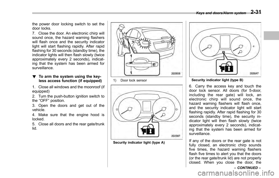
1) Door lock sensor
Security indicator light (type A)
Security indicator light (type B)
6. Carry the access key and touch the
door lock sensor. All doors (for 5-door,
including the rear gate) will lock, an
electronic chirp will sound once, the
hazard warning flashers will flash once,
and the security indicator light will start
flashing rapidly. After rapid flashing for 30
seconds (standby time), the security in-
dicator light will then flash slowly (twice
approximately every 2 seconds), indicat-
ing that the system has been armed for
surveillance.
If any of the doors or the rear gate is not
fully closed, an electronic chirp sounds
five times, the hazard warning flashers
flash five times to alert you that the doors
(or the rear gate/trunk lid) are not properly
closed. When you close the door, the
Keys and doors/Alarm system
–CONTINUED –2-31
Page 146 of 594

Ignition switch (models without“keyless
access with push-button start system ”)......... 3-4
LOCK .................................................................. 3-4
ACC.................................................................... 3-5
ON...................................................................... 3-5
START ................................................................ 3-5
Key reminder chime ............................................ 3-5
Ignition switch light (if equipped) ......................... 3-6
Push-button ignition switch (models with
push-button start system) ............................... 3-6
Safety precautions.............................................. 3-6
Operating range for push-button start system ...... 3-6
Switching power ................................................. 3-7
When access key does not operate properly ........ 3-8
Hazard warning flasher....................................... 3-8
Meters and gauges. ............................................. 3-9
Combination meter illumination ........................... 3-9
Canceling the function for meter/gauge needle movement upon turning on the ignition
switch ............................................................... 3-9
Speedometer ...................................................... 3-10
Odometer ........................................................... 3-10
Double trip meter ............................................... 3-11
Tachometer ........................................................ 3-11
Fuel gauge ......................................................... 3-12
ECO gauge (if equipped) .................................... 3-12
Warning and indicator lights ............................. 3-13Initial illumination for system check .................... 3-13
Seatbelt warning light and chime ........................ 3-14
SRS airbag system warning light ........................ 3-15Front passenger
’s frontal airbag ON and OFF
indicators ........................................................ 3-16
CHECK ENGINE warning light/Malfunction indicator light .................................................. 3-16
Coolant temperature low indicator light/Coolant temperature high warning light ......................... 3-17
Charge warning light .......................................... 3-18
Oil pressure warning light .................................. 3-18
Engine low oil level warning light ....................... 3-18
Windshield washer fluid warning light ................ 3-19
AT OIL TEMP warning light (CVT models) ........... 3-19
Low tire pressure warning light (U.S.-spec. models) ........................................................... 3-19
ABS warning light .............................................. 3-21
Brake system warning light (red) ........................ 3-21
Low fuel warning light ....................................... 3-22
Hill start assist warning light/Hill start assist OFF indicator light .................................................. 3-22
Door open warning light .................................... 3-23
All-Wheel Drive warning light (CVT models) ... ..... 3-23
Power steering warning light .............................. 3-23
Vehicle Dynamics Control warning light/Vehicle Dynamics Control operation indicator light .. ..... 3-24
Vehicle Dynamics Control OFF indicator light ..... 3-25
Warning chimes and warning indicator of the keyless access with push-button start system (if
equipped) ........................................................ 3-25
Security indicator light ....................................... 3-30
Select lever/gear position indicator (CVT models) ........................................................... 3-30
Turn signal indicator lights ................................. 3-31
High beam indicator light ................................... 3-31
Instruments and controls
3