2016 SUBARU IMPREZA brake light
[x] Cancel search: brake lightPage 174 of 594

Inside warningchime Outside warning
chime Access key
warning indica-
tor on meter Operation indica-
tor on push-but-
ton ignition switch Status Action
Long beep
(continuous) Long beep
(continuous)
(Flashes 1 sec.
intermittent) —The driver exited the vehicle with the
access key and closed the driver
’s
door while the push-button ignition
switch is in a position other than
“ OFF ”and the select lever is in a
position other than the “P ”position. Shift the select lever to the
“P ”
position, switch the push-button
ignition switch to “OFF ”and exit the
vehicle.
Long beep
(continuous) —— — Select lever position warning:
The engine is turned off by pressing
the push-button ignition switch and
the select lever is in a position other
than the
“P ”position. Start the engine, shift the select
lever to the
“P ”position, switch the
push-button ignition switch to “OFF ”
and exit the vehicle.
Long beep
(continuous) —— — Select lever position warning:
The driver
’s door was opened while
the push-button ignition switch is in
a position other than “OFF ”and the
select lever is in a position other
than the “P ”position. Shift the select lever to the
“P ”
position, switch the push-button
ignition switch to “OFF ”and exit the
vehicle.
Ding —— — The battery of the access key is low.Replace the battery of the access
key.
Ding —— Flashes in green
(15 seconds
max.) Steering lock warning:
The engine start procedure was
performed, but the steering is still
locked. While turning the steering wheel
right and left lightly, depress the
brake pedal and press the push-
button ignition switch.
Ding —— Flashes
in
orangeSystem malfunction warning:
A malfunction was detected in the
power system or steering lock. Contact a SUBARU dealer immedi-
ately and have the vehicle in-
spected.
Instruments and controls/Warning and indicator lights
–CONTINUED –
3-29
Page 237 of 594

Instruments and controls/Turn signal lever
&Daytime running light system
WARNING
The brightness of the illumination of
the high beam headlights is reduced
by the daytime running light system.
The light switch must always be
turned to the “
”position when it
is dark outside.
The high beam headlights will automati-
cally illuminate at reduced brightness
when the following conditions are fulfilled.
. The engine is running.
. The parking brake is fully released.
. The light control switch is in the
“AUTO ”(if equipped), “
”or off position.
. For CVT models, the select lever is in a
position other than the “P”position.
NOTE
. When the light switch is in the “”
position, the instrument panel illumina-
tion, front side marker lights, tail lights
and license plate lights are also illumi-
nated.
. For models with the auto on/off
headlights, while the light control
switch is in the “AUTO”position and
the system is activated to the auto-on
mode depending on the ambient light level, the high beam headlights that
have illuminated at reduced brightness
turn off, and the low beam headlights
turn on alternatively. At this time, the
instrument panel illumination, front
side marker lights, tail lights and
license plate lights are also illuminated.
Turn signal lever
To activate the right turn signal, push the
turn signal lever up. To activate the left
turn signal, push the turn signal lever
down. When the turn is finished, the lever
will return automatically. If the lever does
not return after cornering, return the lever
to the neutral position by hand.
To signal a lane change, push the turn
signal lever up or down slightly and hold it
during the lane change. The turn signal
indicator lights will flash in the direction of
the turn or lane change. The lever will
return automatically to the neutral position
when you release it.
3-92
Page 286 of 594

&Basic information before use
WARNING
When the vehicle is stopped with the
engine running, always apply the
parking brake for safety. Failure to
do so may result in loss of control of
your vehicle and cause an accident
or serious injury.
CAUTION
. To prevent damaging the screen,
touch the screen keys with your
finger lightly.
. Wipe off fingerprints using a
glass cleaning cloth. Do not use
chemical cleaners to clean the
screen, as they may damage the
touch screen. !
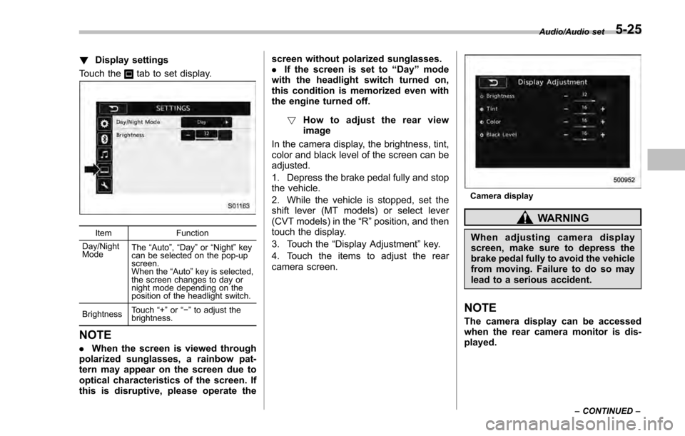
Touch screen gestures
Operations are performed by touching the touch screen directly with your finger.
Operation method OutlineMain use
Touch
Quickly touch and release
once.Changing and selecting various
settings
Drag*
Touch the screen with your
finger, and move the screen
to the desired position.
Scrolling the lists
Flick*
Quickly move the screen by
flicking with your finger.
Scrolling the main screen page
*: The above operations may not be performed on all screens.
NOTEThere may be a delayed response to flick operation that are performed at high
altitudes.
Audio/Audio set
–CONTINUED –5-15
Page 296 of 594

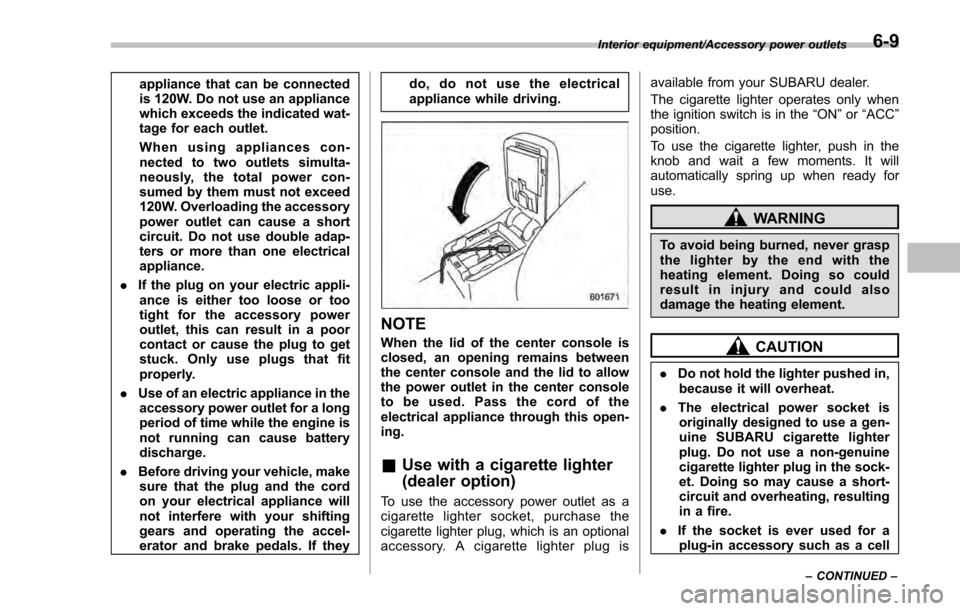
!Display settings
Touch the
tab to set display.
Item Function
Day/Night
Mode The
“Auto ”, “Day ”or “Night ”key
can be selected on the pop-up
screen.
When the “Auto ”key is selected,
the screen changes to day or
night mode depending on the
position of the headlight switch.
Brightness Touch
“+” or“−” to adjust the
brightness.
NOTE
. When the screen is viewed through
polarized sunglasses, a rainbow pat-
tern may appear on the screen due to
optical characteristics of the screen. If
this is disruptive, please operate the screen without polarized sunglasses.
.
If the screen is set to “Day”mode
with the headlight switch turned on,
this condition is memorized even with
the engine turned off.
! How to adjust the rear view
image
In the camera display, the brightness, tint,
color and black level of the screen can be
adjusted.
1. Depress the brake pedal fully and stop
the vehicle.
2. While the vehicle is stopped, set the
shift lever (MT models) or select lever
(CVT models) in the “R”position, and then
touch the display.
3. Touch the “Display Adjustment ”key.
4. Touch the items to adjust the rear
camera screen.
Camera display
WARNING
When adjusting camera display
screen, make sure to depress the
brake pedal fully to avoid the vehicle
from moving. Failure to do so may
lead to a serious accident.
NOTE
The camera display can be accessed
when the rear camera monitor is dis-
played.
Audio/Audio set
–CONTINUED –5-25
Page 374 of 594

appliance that can be connected
is 120W. Do not use an appliance
which exceeds the indicated wat-
tage for each outlet.
When using appliances con-
nected to two outlets simulta-
neously, the total power con-
sumed by them must not exceed
120W. Overloading the accessory
power outlet can cause a short
circuit. Do not use double adap-
ters or more than one electrical
appliance.
. If the plug on your electric appli-
ance is either too loose or too
tight for the accessory power
outlet, this can result in a poor
contact or cause the plug to get
stuck. Only use plugs that fit
properly.
. Use of an electric appliance in the
accessory power outlet for a long
period of time while the engine is
not running can cause battery
discharge.
. Before driving your vehicle, make
sure that the plug and the cord
on your electrical appliance will
not interfere with your shifting
gears and operating the accel-
erator and brake pedals. If they do, do not use the electrical
appliance while driving.
NOTE
When the lid of the center console is
closed, an opening remains between
the center console and the lid to allow
the power outlet in the center console
to be used. Pass the cord of the
electrical appliance through this open-
ing.
&
Use with a cigarette lighter
(dealer option)
To use the accessory power outlet as a
cigarette lighter socket, purchase the
cigarette lighter plug, which is an optional
accessory. A cigarette lighter plug is available from your SUBARU dealer.
The cigarette lighter operates only when
the ignition switch is in the
“ON”or “ACC ”
position.
To use the cigarette lighter, push in the
knob and wait a few moments. It will
automatically spring up when ready for
use.
WARNING
To avoid being burned, never grasp
the lighter by the end with the
heating element. Doing so could
result in injury and could also
damage the heating element.
CAUTION
. Do not hold the lighter pushed in,
because it will overheat.
. The electrical power socket is
originally designed to use a gen-
uine SUBARU cigarette lighter
plug. Do not use a non-genuine
cigarette lighter plug in the sock-
et. Doing so may cause a short-
circuit and overheating, resulting
in a fire.
. If the socket is ever used for a
plug-in accessory such as a cell
Interior equipment/Accessory power outlets
–CONTINUED –6-9
Page 386 of 594

Fuel...................................................................... 7-3Fuel requirements ............................................... 7-3
Fuel filler lid and cap ........................................... 7-4
State emission testing (U.S. only) ...................... 7-7
Preparing to drive ............................................... 7-8
Starting and stopping the engine (models without push-button start system) .................. 7-9
Starting engine.................................................... 7-9
Stopping the engine ........................................... 7-11
Starting and stopping engine (models with
push-button start system) .............................. 7-12
Safety precautions............................................. 7-12
Operating range for push-button start system ............................................................. 7-12
Starting engine ................................................... 7-12
Stopping engine ................................................. 7-13
When access key does not operate properly ....... 7-14
Remote engine start system (dealer
option) .............................................................. 7-14
Models with “keyless access with push-button
start system ”................................................... 7-15
Models without “keyless access with push-button
start system ”................................................... 7-16
Entering the vehicle while it is running via remote start ................................................................. 7-19
Entering the vehicle following remote engine start shutdown ......................................................... 7-19
Pre-heating or pre-cooling the interior of the vehicle ............................................................. 7-19
Service mode (models without “keyless access
with push-button start system ”)........................ 7-19 Remote transmitter program (models without
“keyless access with push-button start
system ”).......................................................... 7-19
System maintenance .......................................... 7-20
Manual transmission ......................................... 7-22Shifting speeds.................................................. 7-22
Driving tips ........................................................ 7-23
Continuously variable transmission ................. 7-23Continuously variable transmission features . ..... 7-24
Select lever ....................................................... 7-24
Selection of manual mode (if equipped) .............. 7-26
Selection of “L”(if equipped) ... .......................... 7-28
Shift lock function ............................................. 7-28
Driving tips ........................................................ 7-29
Power steering ................................................... 7-30Power steering warning light .............................. 7-30
Power steering system features ......................... 7-30
Braking............................................................... 7-31Braking tips ....................................................... 7-31
Brake system .................................................... 7-31
Disc brake pad wear warning indicators ............. 7-32
ABS (Anti-lock Brake System).......................... 7-32ABS self-check.................................................. 7-32
ABS warning light .............................................. 7-33
Electronic Brake Force Distribution (EBD)
system ............................................................. 7-33
Steps to take if EBD system malfunctions .......... 7-33
Vehicle Dynamics Control system.................... 7-34Safety precautions............................................. 7-34
System features ................................................. 7-35
Vehicle Dynamics Control system monitor .......... 7-36
Starting and operating
7
Page 387 of 594

Starting and operating
Vehicle Dynamics Control OFF switch................. 7-36
Tire pressure monitoring system (TPMS)
(U.S.-spec. models) ......................................... 7-38
Parking your vehicle .......................................... 7-40
Parking brake..................................................... 7-40
Parking tips ....................................................... 7-40
Hill start assist system ...................................... 7-41To activate/deactivate the Hill start assist
system ............................................................. 7-43
Hill start assist warning light/Hill start assist OFF indicator light ................................................... 7-44
Cruise control (if equipped). .............................. 7-45To set cruise control.......................................... 7-45
To temporarily cancel the cruise control ............. 7-46To turn off the cruise control
.............................. 7-47
To change the cruising speed ............................ 7-48
Cruise control indicator light .............................. 7-50
Cruise control set indicator light ... ..................... 7-50
BSD/RCTA (5-door models—if equipped) ...... 7-50System features ................................................. 7-51
System operation ............................................... 7-52
BSD/RCTA approach indicator light/warning buzzer ............................................................. 7-54
BSD/RCTA warning indicator .............................. 7-55
BSD/RCTA OFF switch ....................................... 7-56
Certification for the BSD/RCTA ........................... 7-57
Handling of radar sensors .................................. 7-57
Page 395 of 594

Starting and operating/Starting and stopping the engine (models without push–button start system)
. When starting the engine, be sure
to sit in the driver ’s seat (except
when using the remote engine
start system).
NOTE
. Avoid rapid racing and rapid accel-
eration immediately after the engine
has started.
. For a short time after the engine has
started, the engine speed is kept high.
When the warm-up is completed, the
engine speed lowers automatically.
. On rare occasions, it may be difficult
to start the engine depending on the
fuel and the usage condition (repeated
driving of a distance in which the
engine has not warmed up sufficiently).
In such a case, it is recommended that
you change to a different brand of fuel.
. On rare occasions, transient knock-
ing may be heard from the engine when
the accelerator is operated rapidly
such as a rapid start-up and a rapid
acceleration. This is not a malfunction.
. The engine starts more easily when
the headlights, air conditioner and rear
window defogger are turned off.
. After the engine starts, the engine
speed will be kept high until the engine
has warmed up sufficiently. !
MT models
1. Apply the parking brake.
2. Turn off unnecessary lights and ac-
cessories.
3. Depress the clutch pedal to the floor
and shift the shift lever into neutral. Hold
the clutch pedal to the floor while starting
the engine.
The starter motor will only operate when
the clutch pedal is depressed fully to the
floor.
4. Turn the ignition switch to the “ON”
position and check the operation of the
warning and indicator lights. Refer to
“Warning and indicator lights ”F 3-13.
5. Turn the ignition switch to the “START”
position without depressing the accelera-
tor pedal. Release the key immediately
after the engine has started.
If the engine does not start, try the
following procedure.
(1) Turn the ignition switch to the
“LOCK” /“OFF ”position and wait for at
least 10 seconds. After checking that
the parking brake is firmly set, turn the
ignition switch to the “START”position
while depressing the accelerator pedal
slightly (approximately a quarter of the
full stroke). Release the accelerator
pedal as soon as the engine starts.
(2) If this fails to start the engine, turn the ignition switch back to the
“LOCK”/
“ OFF ”position and wait for at least 10
seconds. Then fully depress the accel-
erator pedal and turn the ignition
switch to the “START”position. If the
engine starts, quickly release the
accelerator pedal.
(3) If this fails to start the engine, turn
the ignition switch again to the
“LOCK ”/“OFF ”position. After waiting
for 10 seconds or longer, turn the
ignition switch to the “START ”position
without depressing the accelerator
pedal.
(4) If the engine still refuses to start,
contact your nearest SUBARU dealer
for assistance.
6. Confirm that all warning and indicator
lights have turned off after the engine has
started. The fuel injection system auto-
matically lowers the idle speed as the
engine warms up.
! CVT models
1. Apply the parking brake.
2. Turn off unnecessary lights and ac-
cessories.
3. Shift
the select lever to the “P”or “N”
position (preferably the “P ”position).
The starter motor will only operate when
the select lever is at the “P ”or “N”position.
7-10