Page 382 of 594
&How to use the rear view
camera
When the shift lever/select lever is set to
“R”, the rear view camera automatically
displays the rear view image from the
vehicle. When the lever is set to other
positions, the image before setting to “R”
is displayed.
1. Set the ignition switch to “ON”.
2. Set the shift lever/select lever to “R”.
NOTE
. For models with the genuine
SUBARU navigation system, while the
navigation system is activated, the
image of the rear view camera will not
be displayed. However, the image of
the rear view camera has priority over
other screen displays.
. The image of the rear view camera is
horizontally reversed as is the case
with the vehicle rearview mirror or the
side view mirror.
. It may be difficult to see the image of
the rear view camera in the following
cases. This is not a malfunction of the
camera.
–The vehicle is in a dark place (at
night, in a tunnel, etc.).
– The vehicle is in an extremely hot
or cold place. –
An object (such as raindrops,
snow, dirt, etc.) that disturbs the
view of the rear view camera sticks
to the lens of the camera.
– Strong light shined directly on
the camera lens (occasionally, there
are vertical lines on the screen).
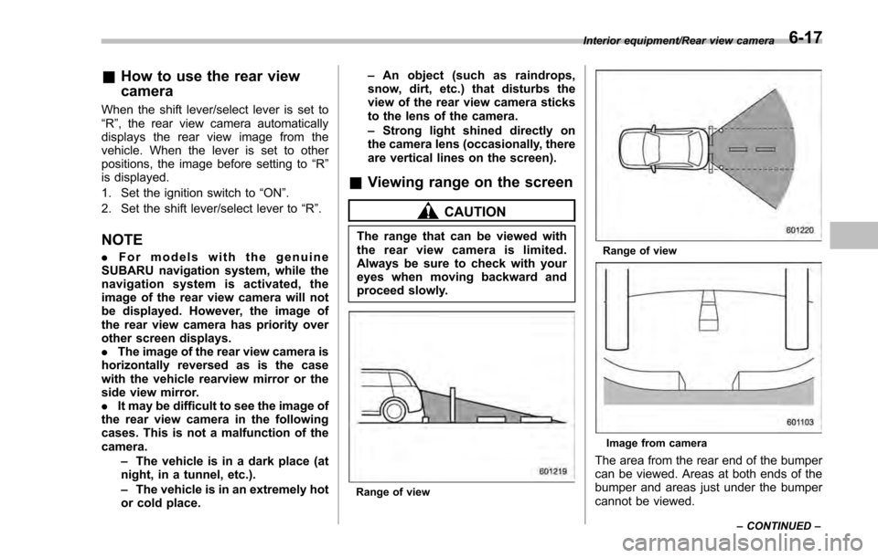
& Viewing range on the screen
CAUTION
The range that can be viewed with
the rear view camera is limited.
Always be sure to check with your
eyes when moving backward and
proceed slowly.
Range of view
Range of view
Image from camera
The area from the rear end of the bumper
can be viewed. Areas at both ends of the
bumper and areas just under the bumper
cannot be viewed.
Interior equipment/Rear view camera
–CONTINUED –6-17
Page 383 of 594
Interior equipment/Rear view camera
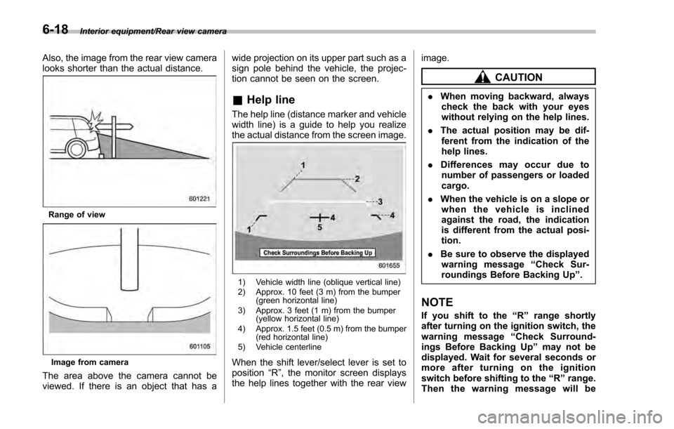
Also, the image from the rear view camera
looks shorter than the actual distance.
Range of view
Image from camera
The area above the camera cannot be
viewed. If there is an object that has awide projection on its upper part such as a
sign pole behind the vehicle, the projec-
tion cannot be seen on the screen.
&
Help line
The help line (distance marker and vehicle
width line) is a guide to help you realize
the actual distance from the screen image.
1) Vehicle width line (oblique vertical line)
2) Approx. 10 feet (3 m) from the bumper
(green horizontal line)
3) Approx. 3 feet (1 m) from the bumper (yellow horizontal line)
4) Approx. 1.5 feet (0.5 m) from the bumper (red horizontal line)
5) Vehicle centerline
When the shift lever/select lever is set to
position “R”, the monitor screen displays
the help lines together with the rear view image.
CAUTION
.
When moving backward, always
check the back with your eyes
without relying on the help lines.
. The actual position may be dif-
ferent from the indication of the
help lines.
. Differences may occur due to
number of passengers or loaded
cargo.
. When the vehicle is on a slope or
when the vehicle is inclined
against the road, the indication
is different from the actual posi-
tion.
. Be sure to observe the displayed
warning message “Check Sur-
roundings Before Backing Up ”.
NOTE
If you shift to the“R”range shortly
after turning on the ignition switch, the
warning message “Check Surround-
ings Before Backing Up ”may not be
displayed. Wait for several seconds or
more after turning on the ignition
switch before shifting to the “R”range.
Then the warning message will be
6-18
Page 384 of 594
displayed.
!Difference between screen image
and actual road
The distance markers show the distance
for a level road when the vehicle is not
loaded. It may be different from the actual
distance depending on the loading condi-
tions or road conditions. !
When there is an upward slope at
the back
1) 3 feet (1 m)
The distance on the screen looks farther
than the actual distance. !
When there is a downward slope
at the back
1) 3 feet (1 m)
The distance on the screen looks nearer
than the actual distance.
NOTE
When cargo is loaded, the rear view
distance on the screen looks farther
thantheactualdistanceasinan
upward slope.
Interior equipment/Rear view camera
–CONTINUED –6-19
Page 385 of 594
Interior equipment/Rear view camera
!Feature of distance marker
1) 3 feet (1 m) line
2) 10 feet (3 m) line
The distance marker shows the distance
on the road. If there is a car or other object
close behind, distance cannot be correctly
displayed.
6-20
Page 439 of 594
Starting and operating/BSD/RCTA (5–door models —if equipped)
&BSD/RCTA approach indica-
tor light/warning buzzer
When the BSD/RCTA is active, the BSD/
RCTA approach indicator light will operate
to alert the driver when there are vehicles
in the neighboring lanes. When reversing
the vehicle, the BSD/RCTA approach
indicator light and warning buzzer will
operate to alert the driver that a vehicle
is approaching from the left or right side.
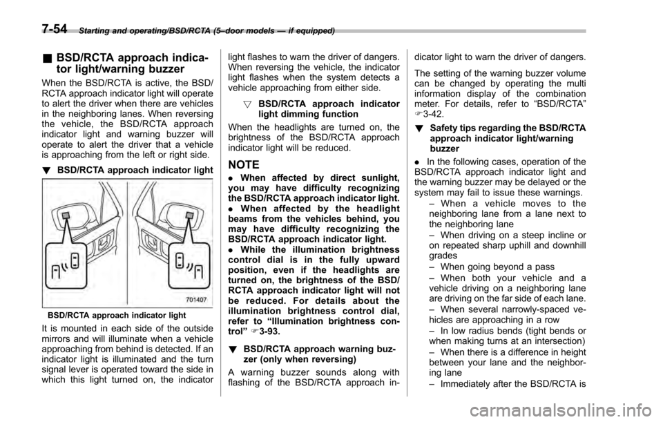
! BSD/RCTA approach indicator light
BSD/RCTA approach indicator light
It is mounted in each side of the outside
mirrors and will illuminate when a vehicle
approaching from behind is detected. If an
indicator light is illuminated and the turn
signal lever is operated toward the side in
which this light turned on, the indicator light flashes to warn the driver of dangers.
When reversing the vehicle, the indicator
light flashes when the system detects a
vehicle approaching from either side.
! BSD/RCTA approach indicator
light dimming function
When the headlights are turned on, the
brightness of the BSD/RCTA approach
indicator light will be reduced.
NOTE
. When affected by direct sunlight,
you may have difficulty recognizing
the BSD/RCTA approach indicator light.
. When affected by the headlight
beams from the vehicles behind, you
may have difficulty recognizing the
BSD/RCTA approach indicator light.
. While the illumination brightness
control dial is in the fully upward
position, even if the headlights are
turned on, the brightness of the BSD/
RCTA approach indicator light will not
be reduced. For details about the
illumination brightness control dial,
refer to “Illumination brightness con-
trol” F3-93.
! BSD/RCTA approach warning buz-
zer (only when reversing)
A warning buzzer sounds along with
flashing of the BSD/RCTA approach in- dicator light to warn the driver of dangers.
The setting of the warning buzzer volume
can be changed by operating the multi
information display of the combination
meter. For details, refer to
“BSD/RCTA”
F 3-42.
! Safety tips regarding the BSD/RCTA
approach indicator light/warning
buzzer
. In the following cases, operation of the
BSD/RCTA approach indicator light and
the warning buzzer may be delayed or the
system may fail to issue these warnings.
–When a vehicle moves to the
neighboring lane from a lane next to
the neighboring lane
– When driving on a steep incline or
on repeated sharp uphill and downhill
grades
– When going beyond a pass
– When both your vehicle and a
vehicle driving on a neighboring lane
are driving on the far side of each lane.
– When several narrowly-spaced ve-
hicles are approaching in a row
– In low radius bends (tight bends or
when making turns at an intersection)
– When there is a difference in height
between your lane and the neighbor-
ing lane
– Immediately after the BSD/RCTA is
7-54
Page 441 of 594
Starting and operating/BSD/RCTA (5–door models —if equipped)
disappear. If the indicator remains dis-
played for a prolonged time, have the
system inspected at a SUBARU dealer.
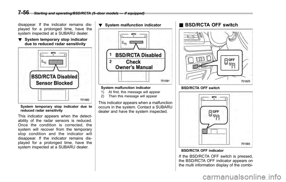
! System temporary stop indicator
due to reduced radar sensitivity
System temporary stop indicator due to
reduced radar sensitivity
This indicator appears when the detect-
ability of the radar sensors is reduced.
Once the condition is corrected, the
system will recover from the temporary
stop condition and the indicator will
disappear. If the indicator remains dis-
played for a prolonged time, have the
system inspected at a SUBARU dealer. !
System malfunction indicator
System malfunction indicator
1) At first, this message will appear
2) Then this message will appear
This indicator appears when a malfunction
occurs in the system. Contact a SUBARU
dealer and have the system inspected.
&BSD/RCTA OFF switch
BSD/RCTA OFF switch
BSD/RCTA OFF indicator
If the BSD/RCTA OFF switch is pressed,
the BSD/RCTA OFF indicator appears on
the multi information display of the combi-
7-56
Page 471 of 594
In case of emergency/If you park your vehicle in case of an emergency
If you park your vehicle in
case of an emergency
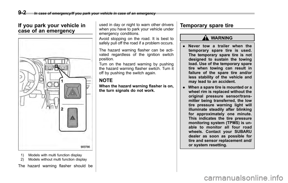
1) Models with multi function display
2) Models without multi function display
The hazard warning flasher should beused in day or night to warn other drivers
when you have to park your vehicle under
emergency conditions.
Avoid stopping on the road. It is best to
safely pull off the road if a problem occurs.
The hazard warning flasher can be acti-
vated regardless of the ignition switch
position.
Turn on the hazard warning by pushing
the hazard warning flasher switch. Turn it
off by pushing the switch again.
NOTE
When the hazard warning flasher is on,
the turn signals do not work.
Temporary spare tire
WARNING
.
Never tow a trailer when the
temporary spare tire is used.
The temporary spare tire is not
designed to sustain the towing
load. Use of the temporary spare
tire when towing can result in
failure of the spare tire and/or
less stability of the vehicle and
may lead to an accident.
. When a spare tire is mounted or a
wheel rim is replaced without the
original pressure sensor/trans-
mitter being transferred, the low
tire pressure warning light will
illuminate steadily after blinking
for approximately one minute.
This indicates the tire pressure
monitoring system (TPMS) is un-
able to monitor all four road
wheels. Contact your SUBARU
dealer as soon as possible for
tire and sensor replacement and/
or system resetting.
9-2
Page 495 of 594
Appearance care/Cleaning the interior
CAUTION
.Do not use organic solvents such
as paint thinners or fuel, or
strong cleaning agents that con-
tain those solvents. Doing so
could damage the surface and
cause the color to deteriorate.
. Do not use chemical solvents
that contain silicone on the vehi-
cle audio system, electrical com-
ponents of the air-conditioner or
any switches. If silicone adheres
to these parts, it may cause
damage to electrical compo-
nents.
& Monitor (if equipped)
To clean the audio/navigation/multi func-
tion display monitor, wipe it with a silicone
cloth or with a soft cloth. If the monitor is
extremely dirty, clean it with a soft cloth
moistened with neutral detergent then
carefully wipe off any remaining detergent.
CAUTION
. Do not spray neutral detergent
directly onto the monitor. Doing
so could damage the monitor ’s
components.
. Do not wipe the monitor with a
hard cloth. Doing so could
scratch the monitor.
. Do not use cleaning fluid that
contains thinner, fuel, or any
other volatile substance. Such
cleaning fluid could erase the
lettering on the switches at the
bottom of the monitor.
10-6