Page 338 of 490
337 4-3. Do-it-yourself maintenance
4
Maintenance and care
Fuse layout and amperage ratings
■Engine compartment
FuseAmpereCircuit
1MIR HTR 7.5 A Outside rear view mirror defoggers
2RDI 25 A Electric cooling fan
3(PUSH-AT) 7.5 A Engine control unit
4ABS NO. 1 40 A ABS
5HEATER 50 A Air conditioning system
6WASHER 10 A Windshield washer
7WIPER 30 A Windshield wipers
8RR DEF 30 A Rear window defogger
9(RR FOG) 10 A�
10D FR DOOR 25 A Power window (driver’s side)
11(CDS) 25 A Electric cooling fan
12D-OP 25 A�
13ABS NO. 2 25 A ABS
14D FL DOOR 25 A Power window (passenger’s side)
15SPARE See note. Spare fuse
Page 339 of 490
338 4-3. Do-it-yourself maintenance
16
SPARE See note. Spare fuse
17SPARE See note. Spare fuse
18SPARE See note. Spare fuse
19SPARE See note. Spare fuse
20SPARE See note. Spare fuse
21ST 7.5 A Starting system
22ALT-S 7.5 A Charging system
23(STR LOCK) 7.5 A Steering lock system
24D/L 20 A Power door lock
25ETCS 15 A Engine control unit
26(AT+B) 7.5 A Transmission
27(AM2 NO. 2) 7.5 AKeyless access with push button
start system
28EFI (CTRL) 15 A Engine control unit
29EFI (HTR) 15 AMultiport fuel injection system/
sequential multiport fuel injection
system
30EFI (IGN) 15 A Starting system
31EFI (+B) 7.5 A Engine control unit
32HAZ 15 ATurn signal lights, hazard warning
flashers
33MPX-B 7.5 AAutomatic air conditioning system,
gauge and meters
34F/PMP 20 AMultiport fuel injection system/
sequential multiport fuel injection
system
35IG2 MAIN 30 ASRS airbag system, engine control
unit
36DCC 30 AInterior light, remote keyless entry
system, main body ECU
FuseAmpereCircuit
Page 341 of 490
340 4-3. Do-it-yourself maintenance
■Instrument panel
FuseAmpereCircuit
1ECU ACC 10 AMain body ECU, outside rear view
mirrors
2P/POINT No.2 15 A Power outlet
3PANEL 10 A Illumination
4TAIL 10 A Tail lights
5DRL 10 A Daytime running light system
6STOP 7.5 A Stop lights
7OBD 7.5 A On-board diagnosis system
8HEATER-S 7.5 A Air conditioning system
9HEATER 10 A Air conditioning system
10FR FOG LH 10 A Left-hand front fog light
11FR FOG RH 10 A Right-hand front fog light
12BK/UP LP 7.5 A Back-up lights
13ECU IG1 10 A ABS, electric power steering
14AM1 7.5 A Starting system
15AMP 15 A�
16AT UNIT 15 A Transmission
17GAUGE 7.5 AGauge and meters, keyless access
with push button start system
18ECU IG2 10 A Engine control unit
19SEAT HTR LH 10 A Left-hand seat heater
20SEAT HTR RH 10 A Right-hand seat heater
21RADIO 7.5 A�
22P/POINT No.1 15 A Power outlet
Page 367 of 490
366
5-1. Essential information
If you think something is wrong
If you notice any of the following symptoms, your vehicle probably
needs adjustment or repair. Contact your SUBARU dealer as soon as
possible.
■Visible symptoms
●Fluid leaks under the vehicle
(Water dripping from the air conditioning after use is normal.)
●Flat-looking tires or uneven tire wear
●Engine coolant temperature gauge needle continually points
higher than normal
■Audible symptoms
●Changes in exhaust sound
●Excessive tire squeal when cornering
●Strange noises related to the suspension system
●Pinging or other noises related to the engine
■Operational symptoms
●Engine missing, stumbling or running rough
●Appreciable loss of power
●Vehicle pulls heavily to one side when braking
●Vehicle pulls heavily to one side when driving on a level road
●Loss of brake effectiveness, spongy feeling, pedal almost
touches the floor
Page 375 of 490

374 5-2. Steps to take in an emergency
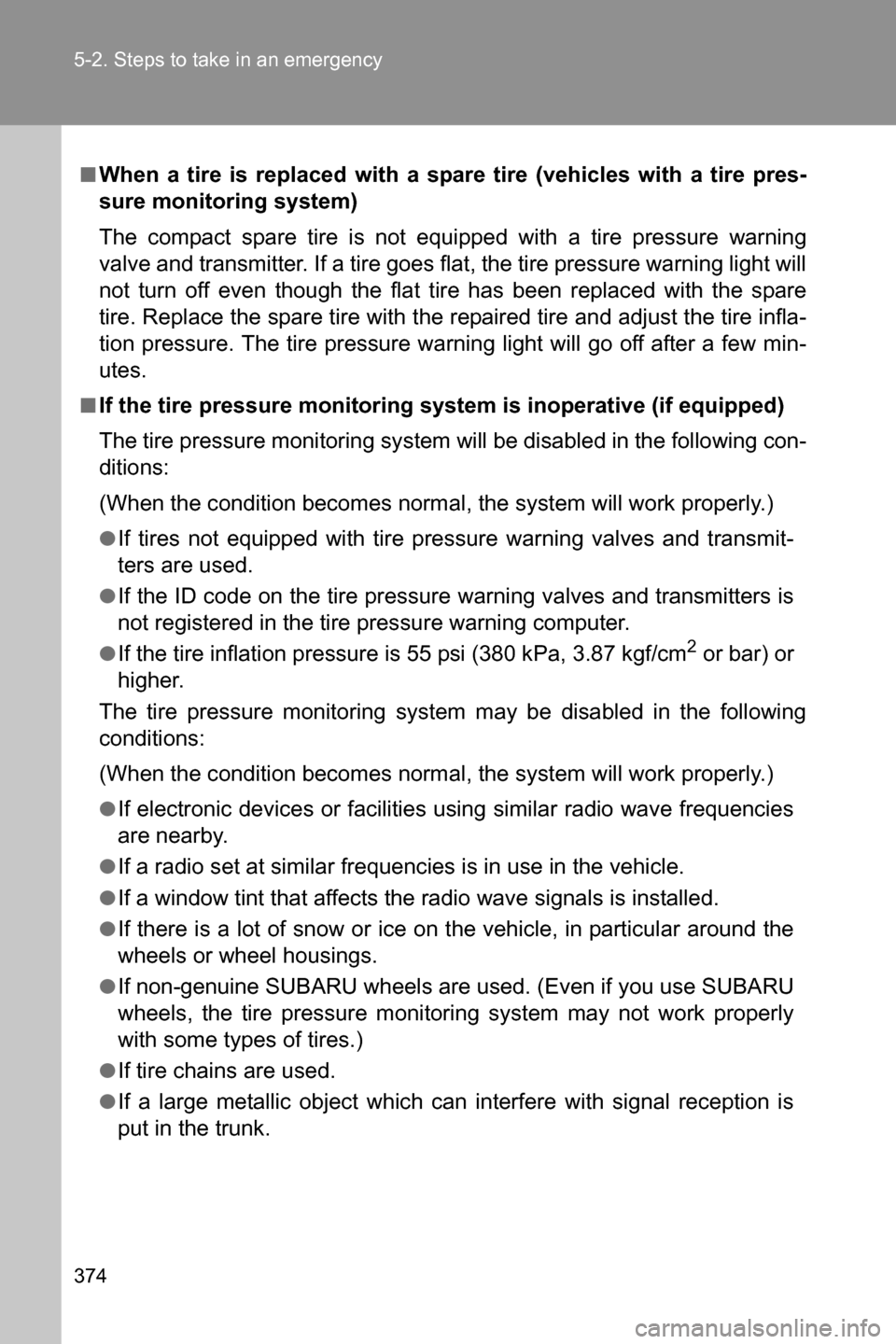
■When a tire is replaced with a spare tire (vehicles with a tire pres-
sure monitoring system)
The compact spare tire is not equipped with a tire pressure warning
valve and transmitter. If a tire goes flat, the tire pressure warning light will
not turn off even though the flat tire has been replaced with the spare
tire. Replace the spare tire with the repaired tire and adjust the tire infla-
tion pressure. The tire pressure warning light will go off after a few min-
utes.
■If the tire pressure monitoring system is inoperative (if equipped)
The tire pressure monitoring system will be disabled in the following con-
ditions:
(When the condition becomes normal, the system will work properly.)
●If tires not equipped with tire pressure warning valves and transmit-
ters are used.
●If the ID code on the tire pressure warning valves and transmitters is
not registered in the tire pressure warning computer.
●If the tire inflation pressure is 55 psi (380 kPa, 3.87 kgf/cm2 or bar) or
higher.
The tire pressure monitoring system may be disabled in the following
conditions:
(When the condition becomes normal, the system will work properly.)
●If electronic devices or facilities using similar radio wave frequencies
are nearby.
●If a radio set at similar frequencies is in use in the vehicle.
●If a window tint that affects the radio wave signals is installed.
●If there is a lot of snow or ice on the vehicle, in particular around the
wheels or wheel housings.
●If non-genuine SUBARU wheels are used. (Even if you use SUBARU
wheels, the tire pressure monitoring system may not work properly
with some types of tires.)
●If tire chains are used.
●If a large metallic object which can interfere with signal reception is
put in the trunk.
Page 405 of 490

404 5-2. Steps to take in an emergency
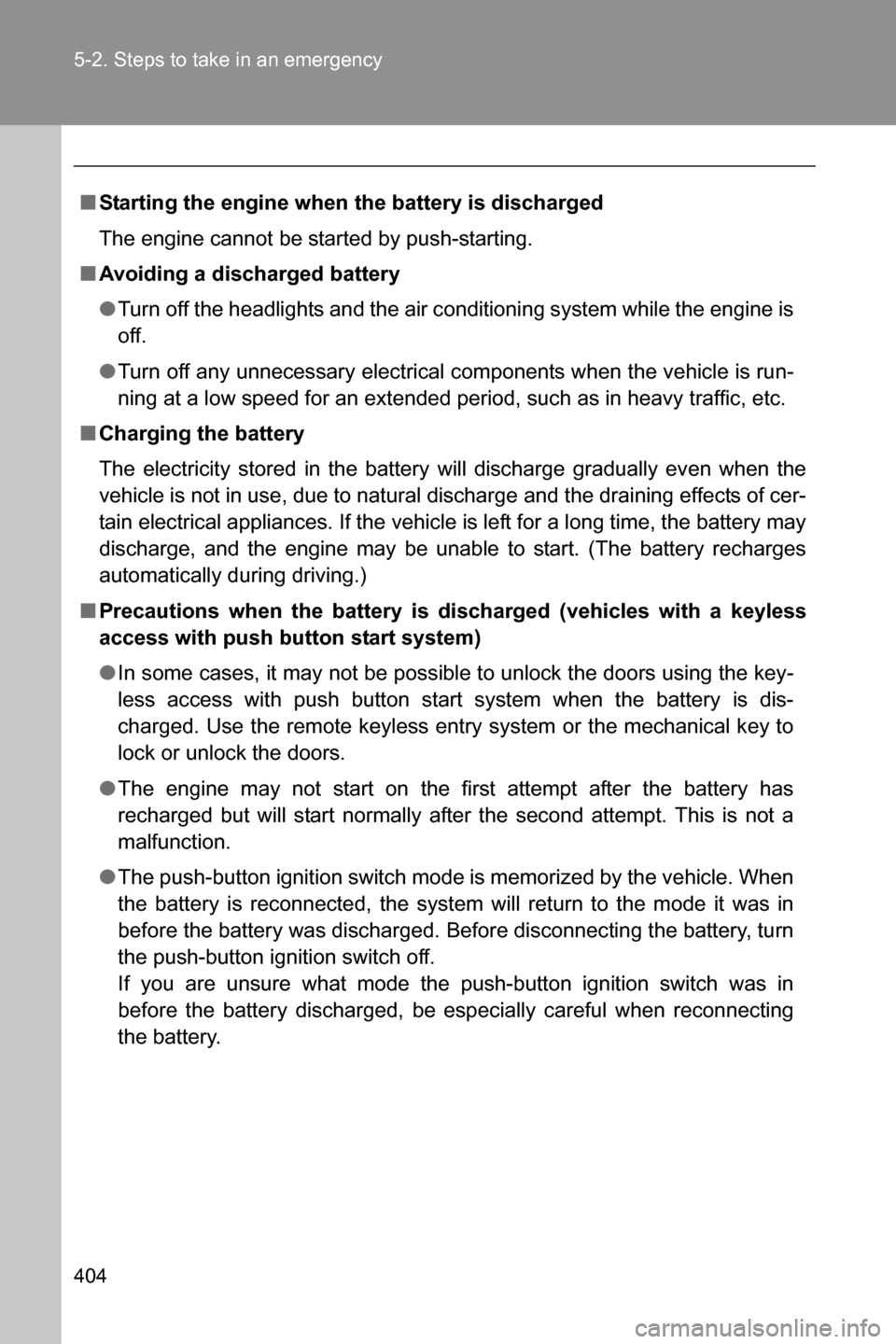
■Starting the engine when the battery is discharged
The engine cannot be started by push-starting.
■Avoiding a discharged battery
●Turn off the headlights and the air conditioning system while the engine is
off.
●Turn off any unnecessary electrical components when the vehicle is run-
ning at a low speed for an extended period, such as in heavy traffic, etc.
■Charging the battery
The electricity stored in the battery will discharge gradually even when the
vehicle is not in use, due to natural discharge and the draining effects of cer-
tain electrical appliances. If the vehicle is left for a long time, the battery may
discharge, and the engine may be unable to start. (The battery recharges
automatically during driving.)
■Precautions when the battery is discharged (vehicles with a keyless
access with push button start system)
●In some cases, it may not be possible to unlock the doors using the key-
less access with push button start system when the battery is dis-
charged. Use the remote keyless entry system or the mechanical key to
lock or unlock the doors.
●The engine may not start on the first attempt after the battery has
recharged but will start normally after the second attempt. This is not a
malfunction.
●The push-button ignition switch mode is memorized by the vehicle. When
the battery is reconnected, the system will return to the mode it was in
before the battery was discharged. Before disconnecting the battery, turn
the push-button ignition switch off.
If you are unsure what mode the push-button ignition switch was in
before the battery discharged, be especially careful when reconnecting
the battery.
Page 437 of 490

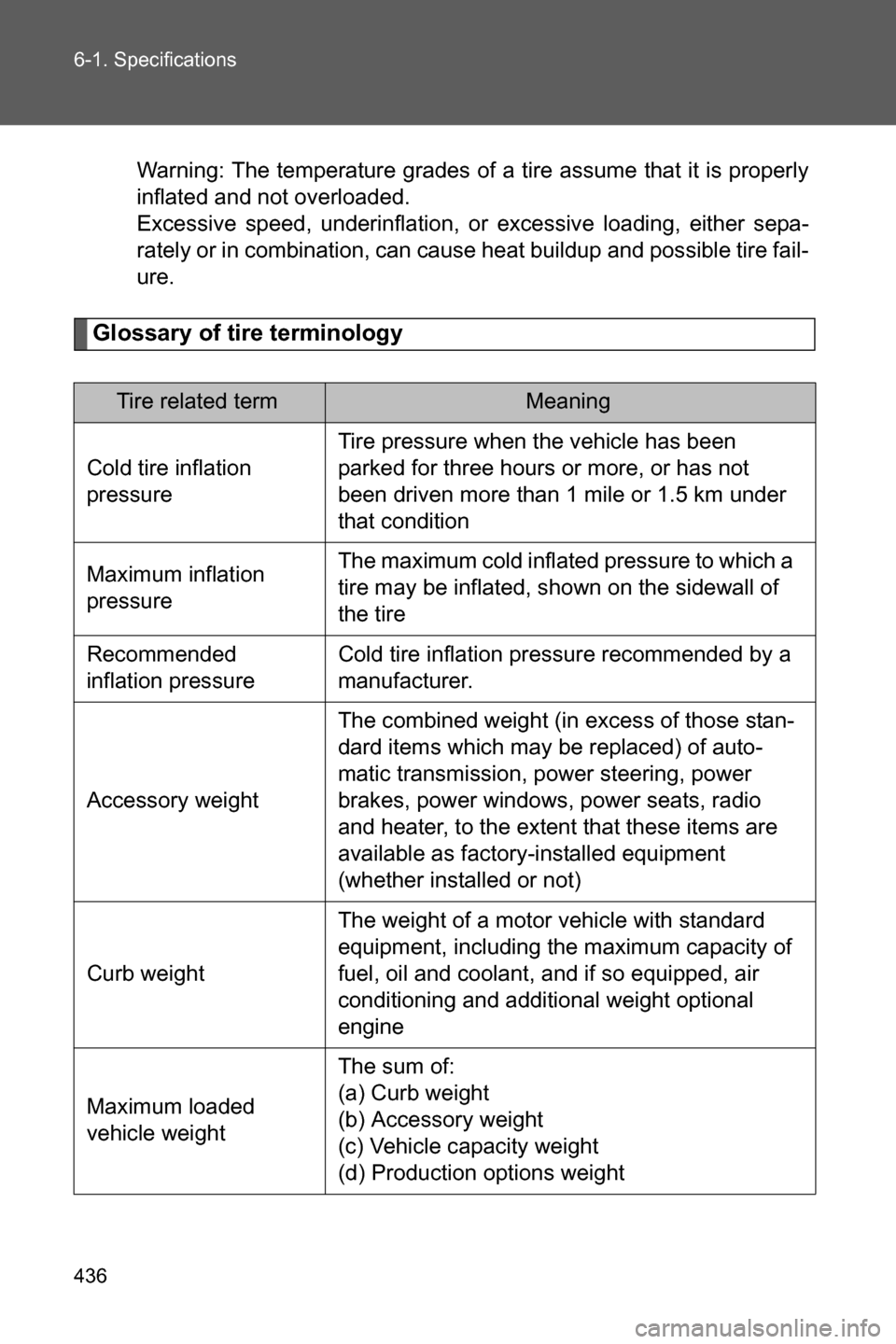
436 6-1. Specifications
Warning: The temperature grades of a tire assume that it is properly
inflated and not overloaded.
Excessive speed, underinflation, or excessive loading, either sepa-
rately or in combination, can cause heat buildup and possible tire fail-
ure.
Glossary of tire terminology
Tire related termMeaning
Cold tire inflation
pressureTire pressure when the vehicle has been
parked for three hours or more, or has not
been driven more than 1 mile or 1.5 km under
that condition
Maximum inflation
pressureThe maximum cold inflated pressure to which a
tire may be inflated, shown on the sidewall of
the tire
Recommended
inflation pressureCold tire inflation pressure recommended by a
manufacturer.
Accessory weightThe combined weight (in excess of those stan-
dard items which may be replaced) of auto-
matic transmission, power steering, power
brakes, power windows, power seats, radio
and heater, to the extent that these items are
available as factory-installed equipment
(whether installed or not)
Curb weightThe weight of a motor vehicle with standard
equipment, including the maximum capacity of
fuel, oil and coolant, and if so equipped, air
conditioning and additional weight optional
engine
Maximum loaded
vehicle weightThe sum of:
(a) Curb weight
(b) Accessory weight
(c) Vehicle capacity weight
(d) Production options weight
Page 462 of 490

461
7
For owners
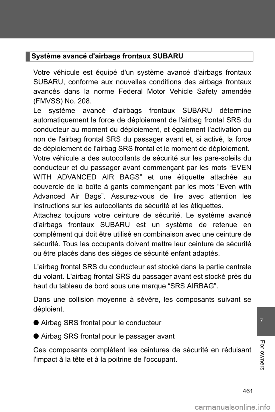
Système avancé d'airbags frontaux SUBARU
Votre véhicule est équipé d'un système avancé d'airbags frontaux
SUBARU, conforme aux nouvelles conditions des airbags frontaux
avancés dans la norme Federal Motor Vehicle Safety amendée
(FMVSS) No. 208.
Le système avancé d'airbags frontaux SUBARU détermine
automatiquement la force de déploiement de l'airbag frontal SRS du
conducteur au moment du déploiement, et également l'activation ou
non de l'airbag frontal SRS du passager avant et, si activé, la force
de déploiement de l'airbag SRS frontal et le moment de déploiement.
Votre véhicule a des autocollants de sécurité sur les pare-soleils du
conducteur et du passager avant commençant par les mots “EVEN
WITH ADVANCED AIR BAGS” et une étiquette attachée au
couvercle de la boîte à gants commençant par les mots “Even with
Advanced Air Bags”. Assurez-vous de lire avec attention les
instructions sur les autocollants de sécurité et les étiquettes.
Attachez toujours votre ceinture de sécurité. Le système avancé
d'airbags frontaux SUBARU est un système de retenue en
complément qui doit être utilisé en combinaison avec une ceinture de
sécurité. Tous les occupants doivent mettre leur ceinture de sécurité
ou être placés dans des sièges de sécurité enfant adaptés.
L'airbag frontal SRS du conducteur est stocké dans la partie centrale
du volant. L'airbag frontal SRS du passager avant est stocké près du
haut du tableau de bord sous une marque “SRS AIRBAG”.
Dans une collision moyenne à sévère, les composants suivant se
déploient.
●Airbag SRS frontal pour le conducteur
●Airbag SRS frontal pour le passager avant
Ces composants complètent les ceintures de sécurité en réduisant
l'impact à la tête et à la poitrine de l'occupant.