2016 SKODA KODIAQ gearbox
[x] Cancel search: gearboxPage 45 of 344

ServiceRead and observe
on page 34 first.
illuminates – information regarding a service appointment that is due
» page 49 , Service interval display .
Information system
Driver information system
Introduction
This chapter contains information on the following subjects:
Display in the instrument cluster
43
Setting the clock
44
Gear recommendation
44
Vehicle condition
45
Display in the instrument cluster
Fig. 24
Display types: MAXI DOT / Segment Display
Depending on the vehicle's equipment, the information system uses the dis- play in the instrument cluster to provide the following information » Fig. 24.
Time / symbols of the Infotainment voice control
Engaged gear / gear recommendation
Selector lever positions for the automatic gearbox
Warning lights of the START-STOP system
Compass display 1)
Detected traffic signs
Driving data (multifunction display)
Warning lights
Information messages
1231)
Applies to vehicles with factory-installed navigation system.
43Information system
Page 46 of 344

Door alarm
Eco tips
Service interval display
Outside temperature
Cruise control / speed limiter
Total distance travelled
Distance travelled by resetting the memory (trip)
Time
Warning lights of the START-STOP system
Engaged gear / gear recommendation
Selector lever positions for the automatic gearbox
Outside temperature
Warning lights
Driving data (multifunction display)
Total distance travelled
Distance travelled by resetting the memory (trip)
Cruise control / speed limiter
Service interval display
Information messages
Door, luggage compartment and bonnet alarm
When the door or luggage compartment / bonnet is open, a graphic warning
appears in the display.
An acoustic signal will also sound if you drive the vehicle above 6 km/h when a
door is open.
Reset counter for distance travelled (trip)›
Press button
A
» Fig. 25 on page 44 .
Setting the clock
Fig. 25
Button in the instrument cluster
45678910›Switch on the ignition.›Press and hold the buttonA
» Fig. 25 until the
time
is shown in the display.›
Release the button
A
and the system switches to the hour setting function.
›
Press the button
A
again and set the hours.
›
Wait 4 seconds, the system switches to the minutes setting.
›
Press the button
A
again and set the minutes.
›
Wait 4 seconds, the system switches to the initial setting.
The time can also be adjusted in Infotainment by tapping
→
→
Time anddate
.
Gear recommendation
Fig. 26
Information on the selected
gear / Gear recommendation
A suitable engaged gear or, where appropriate, a recommended gear is dis-
played, with the aim of conserving the life of the engine and increasing driving
efficiency.
Display » Fig. 26
Optimal gear engaged
Gear recommendation (e.g.
means that it is advantageous to switch
from 3rd to 4th gear)
For vehicles with automatic transmission the recommended gear will be
shown provided the mode for manual switching (Tiptronic) is selected.
WARNINGThe driver is always responsible for selecting the correct gear in different
driving situations, such as overtaking.44Operation
Page 55 of 344
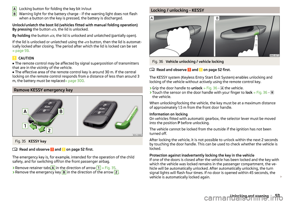
Locking button for folding the key bit in/out
Warning light for the battery charge - if the warning light does not flash
when a button on the key is pressed, the battery is discharged.
Unlock/unlatch the boot lid (vehicles fitted with manual folding operation)
By pressing the button
, the lid is unlocked.
By holding the button
, the lid is unlocked and unlatched (partially open).
If the lid is unlocked or unlatched using the
button, then the lid is automat-
ically locked after closing. The period after which the lid is locked can be set
» page 59 .
CAUTION
■
The remote control may be affected by signal superposition of transmitters
that are in the vicinity of the vehicle.■
The effective area of the remote control key is around 30 m. If the central
locking on the remote control responds from a distance of less than around 3
m, the battery must be replaced » page 300.
Remove KESSY emergency key
Fig. 35
KESSY key
Read and observe
and on page 52 first.
The emergency key is, for example, intended for the operation of the child
safety, and for switching off/on the front passenger airbag.
›
Remove retainer tabs
A
in the direction of arrow
1
» Fig. 35 .
›
Remove the emergency key
B
in the direction of the arrow
2
.
ABLocking / unlocking - KESSYFig. 36
Vehicle unlocking / vehicle locking
Read and observe
and on page 52 first.
The KESSY system (Keyless Entry Start Exit System) enables unlocking and
locking of the vehicle without actively using the remote control key.
›
Grip the door handle to unlock » Fig. 36 -
the vehicle.
›
Touch the sensor on the door handle with your finger to
lock » Fig. 36 -
the vehicle.
When unlocking/locking the vehicle, the key must be at a maximum distance
of approximately 1.5 m from the front door handle.
Information on locking
On vehicles fitted with automatic gearbox, the selector lever must be moved
into the position P before unlocking.
The vehicle cannot be locked from the outside if the ignition has not been
turned off.
After locking the vehicle, it is not possible to unlock within the next 2 seconds
by touching the door handle. This can be used to check whether the vehicle is
locked.
Protection against inadvertently locking the key in the vehicle
If one of the doors is closed after the vehicle has been locked and the key with
which the vehicle was locked remains in the passenger compartment, the ve-
hicle will be automatically unlocked. After automatically unlocking, the turn
signal lights will flash four times. If no door is opened within 45 seconds, the
vehicle is automatically locked again.
53Unlocking and opening
Page 212 of 344

WARNING (Continued)■If the vehicle stalls, with engine running, in the D, S , R or Tiptronic mode,
then the vehicle must be prevented from rolling away by means of the
brake pedal, parking brake or using the Auto Hold function. Even when the
engine is idling, the power transmission is never completely interrupted –
the vehicle creeps.■
When leaving the vehicle, the selector lever must always be set to P .
Otherwise, the vehicle could start to move - risk of accident.
CAUTION
■ If you want to move the selector lever from position N to position D / S whilst
driving, the engine must be running at idling speed.■
When stopping on a slope, never try to hold the vehicle using the accelerator
pedal – this may lead to gear damage.
Select selector lever position
Fig. 259
Selector lever settings / display
Read and observe and on page 209 first.
Move the selector lever to change to the following positions » Fig. 259. In
some positions you have to push the locking button » page 210, Selector lever
lock .
When the ignition is switched on, the gearbox mode and the currently selected
gear are indicated in the display » Fig. 259.
Park - the position can be set only when the vehicle is at a standstill.
The drive wheels are mechanically locked.
Reverse gear - the position can be set only when the vehicle is at a stand-
still and the engine is at idling speed.
Neutral (idle position) - the power transmission to the drive wheels is in-
terrupted.
PRNForward mode / sports programme - the gear change takes place in the
position S at higher engine speeds than in mode D
(Sprung position) - choice between positions D and S
If the Sport driving mode is selected with the engine running » page 251, Se-
lect the driving mode (Driving Mode Selection) , the transmission is automati-
cally set in the S mode.
E – Economical driving mode
If the driving mode Eco or Individual (engine - Eco) » page 251 is selected and
the selection lever is in the setting D/S, the transmission is automatically set
to mode E. This mode cannot be selected with the selector lever.
The forwards mode is switched up or down automatically in mode E at lower
engine speeds than in mode D.
Selector lever lock
Fig. 260
Shift lock button
Read and observe
and on page 209 first.
The selector lever is locked in mode P and N to prevent that the forward driv-
ing is selected accidentally, thereby setting the vehicle in motion.
The selector lever is locked only when the vehicle is stationary and at speeds
up to 5 km/h.
The selector lever lock is indicated by the illumination of the warning light.
Disengage selector lever from P mode or N
›
Press the brake pedal and the lock button at the same time in the direction
of
1
» Fig. 260
-
.
D/S210Driving
Page 213 of 344

To move the selector lever from mode N to D / S only the brake pedal is press-
ed.
The selector lever is not locked when quickly moving across the position N
(e.g. from R to D/S ). This, for example, helps to rock out a vehicle that is stuck,
e.g. in a bank of snow. The selector lever lock will engage if the lever is in posi-
tion N for more than approx. 2 seconds without the brake pedal being de-
pressed.
If it is not possible to release the gear selector from mode P in the usual man-
ner, then this can be emergency unlocked » page 303.
Note
If you want to switch the selector lever from mode P to mode D/S or vice ver-
sa, move the selector lever quickly. This prevents that you accidentally select
mode R or N.
Manual shifting of gears (Tiptronic)
Fig. 261
Selector lever/multi function steering wheel
Read and observe
and on page 209 first.
Tiptronic mode makes it possible to manually shift gears with the selector lev-
er or multifunction steering wheel.
Switching to manual shifting using the selector lever
›
Push the gear selector from position D/S towards the right, or left in a right-
hand drive vehicle. The current gear is maintained.
Switching to manual shifting by using the rocker switches under the
multifunction steering wheel
›
To change gear , pull one of the rocker switches
-
/
+
briefly towards the
steering wheel » Fig. 261.
›To
cancel manual shift, pull the rocker switch + towards the steering wheel
for more than 1 s.
If you do not pull one of the rocker switches -
/
+
for more than 1 minute,
manual shifting of the gears is deactivated automatically.
Changing gear
›
To shift up , tap the selector lever forwards
+
or pull the rocker switch
+
briefly towards the steering wheel » Fig. 261.
›
To shift down , tap the selector lever backwards
-
or pull the rocker switch
-
briefly towards the steering wheel » Fig. 261.
The currently selected gear is indicated in the display » Fig. 259 on page 210 .
The gear shift indicator should be observed when changing gear » page 44.
When accelerating, the gearbox automatically shifts up into the higher gear
just before the maximum permissible engine speed is reached. If a lower gear
is selected, the gearbox does not shift down until there is no risk of the engine
over revving.
Note
It may be beneficial, for example, when travelling downhill, to use manual
shifting of gears. Shifting to a lower gear reduces the load on the brakes and
hence the wear of the brakes.
Start and drive
Read and observe
and on page 209 first.
Starting and temporarily pausing
›
Firmly depress and hold the brake pedal.
›
Start the engine.
›
Press the locking button and move the selector lever to the desired position
» page 210 .
›
Release the brake pedal and accelerate.
The selector lever position N does not have to be selected if stopping for a
short time, such as at cross roads. However, you must apply the brake pedal in
order to prevent the vehicle from rolling away.
Accelerate to max. speed during the journey (kickdown function)
The kickdown function is applied when the accelerator pedal is pressed down
in the forward mode.
The gear change is adjusted accordingly to reach the maximum acceleration.
211Starting-off and Driving
Page 253 of 344

MalfunctionsRead and observe
and on page 248 first.
If, for some unknown reason, the system is not available, an appropriate mes-
sage appears in the display of the instrument cluster.
Sensor covered / dirty
If the sensor cover or the sensor is dirty or covered, a message appears on the
instrument cluster display stating there is no sensor view. Clean the sensor
cover or remove the obstacles » Fig. 264 on page 215 .
If there is no sensor view in the winter, the snow on the sensor under the cov-
er could be the reason. The system is functional again after the snow melts
away from the sensor.
System unavailable
If the system is currently unavailable, a message concerning the unavailability
appears. Stop the vehicle, switch off the engine and then start it again. If the
system still is not available, seek the assistance of a specialist garage.
Select the driving mode (Driving Mode Selection)
Introduction
This chapter contains information on the following subjects:
Adaptive Chassis Control (DCC)
251
Mode
Eco251
Mode
Comfort252
Mode
normal252
Mode
Sports252
mode
individual252
Mode
Snow252
Mode selection and Infotainment display
252
Individual mode
settings253
By selecting the driving mode, the driving behaviour can be adapted to the de-
sired mode of operation.
The following modes
Eco
,
Comfort
,
Normal
,
Sport
,
Individual
and
Snow
are available.
The mode
Comfort
is only available on vehicles with adaptive chassis control
(DCC).
WARNINGPlease take note of the general points relating to the use of assistance
systems » page 215, in section Introduction .
Adaptive Chassis Control (DCC)
Read and observe
on page 251 first.
The adaptive chassis control (following known as DCC) provides the ability toadjust the shock characteristics for the sporty, normal or comfortable driving
when the corresponding control mode is selected.
The DCC evaluates steering response and road conditions while driving contin-
uously and adjusts the suspension behaviour within the selected driving mode
accordingly.
Mode
Eco
Read and observe on page 251 first.
This mode is suitable for a relaxed style of driving and helps to save fuel.
Selecting this mode primarily affects the function of the following systems.
Drive
Vehicle acceleration is more relaxed than in
Normal
mode.
The recommended gear is controlled such to achieve the lowest possible fuel
consumption » page 44.
If the START-STOP system is deactivated manually » page 205, this will be au-
tomatically activated.
The automatic gearbox is set automatically to mode E » page 210 .
Adaptive Cruise Control (ACC)
Acceleration occurs more relaxed than in
Normal
» page 243 mode with distance
control.
Headlights with LED lamps
The system is in economy mode » page 68. The headlamps are in basic setting
and do not adapt to the direction of travel.
251Assist systems
Page 265 of 344
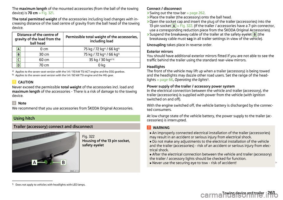
The maximum length of the mounted accessories (from the ball of the towing
device) is 70 cm » Fig. 321 .
The total permitted weight of the accessories including load changes with in-
creasing distance of the load centre of gravity from the ball head of the towing
device.Distance of the centre of
gravity of the load from the ball headPermissible total weight of the accessories, including loadA0 cm75 kg / 72 kga)
/ 66 kg b)B30 cm75 kg / 72 kg a)
/ 66 kg b)C60 cm35 kg / 30 kg a)
b)D70 cm0 kga)
Applies to the seven-seat version with the 1.4 / 110 kW TSI ACT engine and the DSG gearbox.
b)
Applies to the seven-seat version with the 1.4 / 92 kW TSI engine and the MG-gear.
CAUTION
Never exceed the permissible
total weight of the accessories incl. load and
maximum length of the accessories - There is a risk of damage to the towing
device.
Note
We recommend that you use accessories from ŠKODA Original Accessories.
Using hitch
Trailer (accessory) connect and disconnect
Fig. 322
Housing of the 13 pin socket,
safety eyelet
Connect / disconnect›Swing out the tow bar » page 262.›
Place the trailer (the accessory) onto the ball head.
›
Open the socket cap and insert the plug of the trailer (accessories) into the
13-pin socket
A
» Fig. 322 . (If the trailer / accessories have a 7-pin connector,
use a corresponding reduction piece from the ŠKODA Original Accessories).
›
Suspend the breakaway cable of the trailer at the safety eyelet
B
(the
breakaway cable must sag in all trailer settings in view of the vehicle).
Uncoupling takes place in reverse order.
Exterior mirrors
You should have additional exterior mirrors fitted if you are not able to see the
traffic behind the trailer using the standard rear-view mirrors.
Headlights
The front of the vehicle may lift up when a trailer (accessory) is being towed
and the headlights may dazzle other road users. Set the range of the head-
lights » page 66 , Operating the lights 1)
.
Power supply of the trailer / accessory power system
In the electrical connection between the vehicle and trailer (accessory), the
trailer (accessories) is supplied with power from the vehicle (with ignition
switched on and off).
With the engine switched off, the vehicle battery is discharged by the connec-
ted consumers.
At low charge state of the vehicle battery, the power supply to the trailer (ac-
cessories) is interrupted.
WARNING■ An improperly connected electrical installation of the trailer (accessories)
may result in an accident or serious injury from electrical shock.■
Do not make any adjustments to the electrical installation of the vehicle
and the trailer (accessories) - risk of an accident or serious injury from elec-
trical shock.
■
After the electrical connection between the vehicle and trailer (accessory)
the trailer / accessory lights should be checked for function.
■
Never use the securing eye to tow - risk of accident!
1)
Does not apply to vehicles with headlights with LED lamps.
263Towing device and trailer
Page 301 of 344

Conditions for towing.Cars with automatic gearboxes must not be towed with the rear wheels
raised - there is a risk of gearbox damage!
If the gearbox has no oil, your vehicle must be towed with the front axle
raised clear of the ground or on a breakdown vehicle or trailer.
The maximum towing speed is 50 km/h.
The vehicle must be transported on a special breakdown vehicle or trailer
if it is not possible to tow in the vehicle in the way described or if the tow-
ing distance is greater than 50 km.
Driver of the tow vehicle›
On vehicles with manual transmission , engage gear slowly when starting.
›
On vehicles with automatic transmission , accelerate with particular care.
›
Only then approach correctly when the rope is taut.
Driver of the towed vehicle
›
If possible, the vehicle should be towed with the engine running. Operate the
brake booster and power steering only if the engine is running, otherwise
the brake pedal must be depressed more strongly and more power has to be
directed to the steering.
›
If it is not possible to start the engine, switch on the ignition so that the
steering wheel is not locked and so that the turn signal lights, windscreen
wipers and windscreen washer system can be used.
›
Take the vehicle out of gear or move the selector lever into position N if the
vehicle is fitted with an automatic gearbox.
›
Always keep the tow rope taut during the towing procedure.
WARNING■ Wound tow ropes must not be used for towing » Fig. 351- , the towing
eye may unscrew out of the vehicle - risk of accident.■
Ensure tow rope is not twisted - risk of accident.
CAUTION
■ Do not tow-start the engine – risk of damaging the engine! The battery from
another vehicle can be used as a jump-start aid » page 297, Jump-starting .■
In the case of off-road towing manoeuvres, for both vehicles there is the risk
that the fastening parts could be overloaded and damaged.
Note
We recommend that you use the tow rope from ŠKODA Original Accessories.Front towing eyeFig. 352
Remove protective grille / install towing eye
Removing/inserting protective grille
›
To remove , insert the clamp for taking off the full wheel trims in the recess
in the protective grille and remove the protective grille in the direction of ar-
row
1
» Fig. 352 .
›
To insert , insert the protective grille in the opening and push in gently. The
protective grille must engage firmly.
Removing/installing the towing eye
›
To fit, screw in the towing eye by hand in the direction of the arrow
2
» Fig. 352 until it clicks into place » .
For tightening purposes, we recommend, for example, using the wheel
wrench, towing eye from another vehicle or a similar object that can be pushed through the eye.
›
To remove it, unscrew the towing eye in the opposite direction to arrow
2
.
WARNINGThe towing eye must always be tightened, otherwise the towing eye may
break during the towing.299Emergency equipment and self-help