Page 206 of 300
3.28
Refitting the luggage
compartment cover
Position the side 3 of the luggage com-
partment cover in its housing, press the
side 3 and position the opposite side
into its housing.
Luggage compartment cover
storage
Version without emergency spare
wheel
Lift the false floor 4, then position the
luggage cover roller 2. Attach it using
the elastic cords 5 on each side of the
boot.
To remove the flexible
section of the luggage cover
Pull then lift the handle 1 gently.
Guide the luggage cover onto the
roller 2.
Removing the luggage cover
Press the side 3 of the luggage cover 2
(movement A), release the opposite
side from its housing then lift, remove
the whole cover.
LUGGAGE COMPARTMENT COVER
3
4
5
2
Do not place any heavy or
solid objects on the luggage
cover. These may pose a
risk to the vehicle occu-
pants if the driver has to brake sud-
denly or if the vehicle is involved in
an accident.
1
2
5
4
A
Page 207 of 300
3.29
Storage position
This allows for more space to store
things in the boot.
– Remove part B then part A of the
mobile floor 1;
– place part A in the luggage com-
partment under the supports 3 then
part B.
BOOT FITTINGS (1/2)
A
Mobile floor 1(depending on the vehicle)
It is made up of two independent and
interchangeable parts, A and B . The
smooth side is easy to clean.
Flat position
It allows you to have a flat floor by fold-
ing down the back of the rear bench
seat.
The mobile floor is positioned on sup-
ports 3.
Maximum load allowed on the
mobile floor when flat: 50 kg evenly
distributed.
Intermediate position
This enables you to compartmentalise
the boot into two separate spaces.
– Remove the part B of the mobile
floor;
– place it in the boot using the runners provided 2.
1
1
B
123
Page 208 of 300
3.30
BOOT FITTINGS (2/2)
Bag hooks 4
Maximum weight per hook: 5 kg.
Anchorage points
Attachment points 5
If your vehicle is not equipped with
anchorage points, you can get them
from an authorised dealer.
4
5
Page 209 of 300

3.31
Always position the heavi-
est items directly on the
floor. Use the lashing
points 1 on the boot floor, if
these are fitted to the vehicle. The
luggage should be loaded in such a
way that no items will be thrown for-
ward and strike the occupants if the
driver has to brake suddenly. Fasten
the rear seat belts, even if the seats
are not occupied.
TRANSPORTING OBJECTS IN THE LUGGAGE COMPARTMENT
Always position the objects transported
so that the largest surface is against:
– The rear bench seatback for normal loads (example A).
– The front seatbacks with the rear
seatbacks folded down, the mobile
floor in the flat-floor position (exam-
ple B).
– The front seatbacks with the rear seatbacks folded down, the mobile
floor in the stored-away position, as is
the case for maximum loads (exam-
ple C).
If you have to place objects on the folded
seatback, it is necessary that you lower
the headrests before folding the seat-
back so that it can be folded as flat as
possible against the seat.
B
A
1
C
Page 237 of 300
5.3
Emergency spare wheel A
To get to it:
– open the tailgate;
– Depending on the vehicle, lift up the mobile floor;
– lift the boot carpet;
– remove the tool kit by lifting it by its handles;
– unscrew the central mounting;
– remove the emergency spare wheel.
Note: Store the punctured wheel in the
storage bag provided, along with the
tool kit and put them in the boot.
PUNCTURE, EMERGENCY SPARE WHEEL (2/2)
If the vehicle is parked on
the hard shoulder, you must
warn other road users of
your vehicle’s presence
with a warning triangle or with other
devices as per the legislation apply-
ing to the country you are in.
A
Page 239 of 300

5.5
TYRE PRESSURE KIT (2/3)
In the event of a puncture, use the kit
located in the boot, underneath the
boot carpet.
With the engine running and the
parking brake applied,
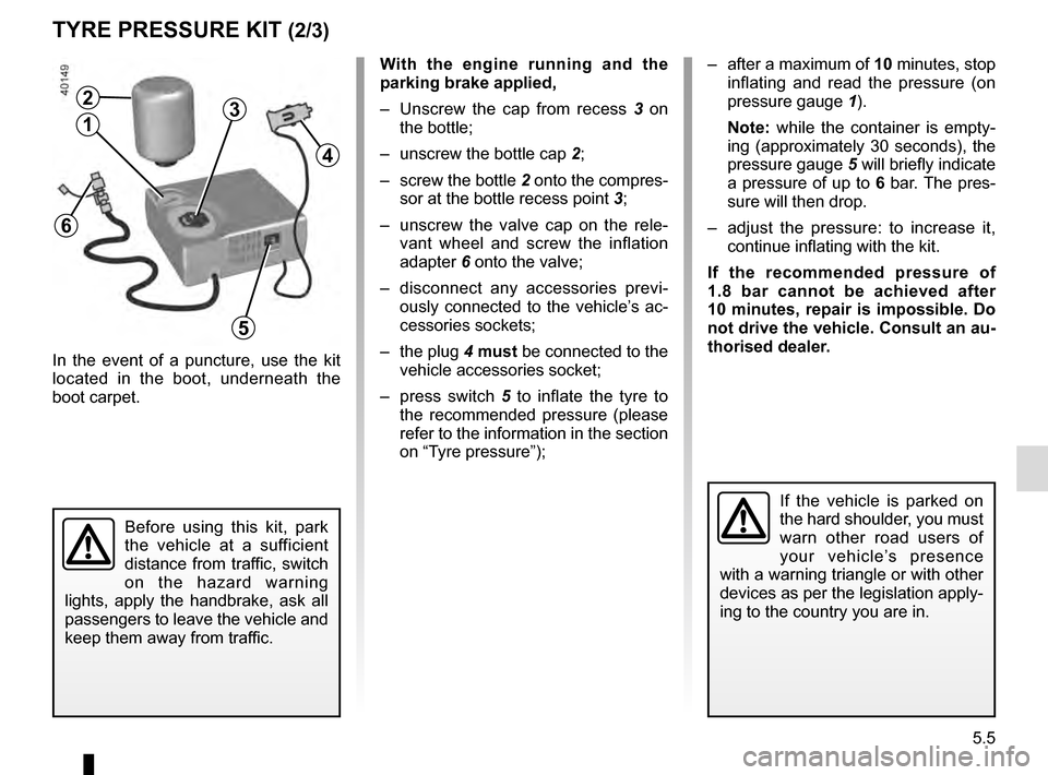
– Unscrew the cap from recess 3 on
the bottle;
– unscrew the bottle cap 2;
– screw the bottle 2 onto the compres- sor at the bottle recess point 3;
– unscrew the valve cap on the rele- vant wheel and screw the inflation
adapter 6 onto the valve;
– disconnect any accessories previ- ously connected to the vehicle’s ac-
cessories sockets;
– the plug 4 must be connected to the
vehicle accessories socket;
– press switch 5 to inflate the tyre to
the recommended pressure (please
refer to the information in the section
on “Tyre pressure”);
Before using this kit, park
the vehicle at a sufficient
distance from traffic, switch
on the hazard warning
lights, apply the handbrake, ask all
passengers to leave the vehicle and
keep them away from traffic.
If the vehicle is parked on
the hard shoulder, you must
warn other road users of
your vehicle’s presence
with a warning triangle or with other
devices as per the legislation apply-
ing to the country you are in.
– after a maximum of 10 minutes, stop inflating and read the pressure (on
pressure gauge 1).
Note: while the container is empty-
ing (approximately 30 seconds), the
pressure gauge 5 will briefly indicate
a pressure of up to 6 bar. The pres-
sure will then drop.
– adjust the pressure: to increase it, continue inflating with the kit.
If the recommended pressure of
1.8 bar cannot be achieved after
10 minutes, repair is impossible. Do
not drive the vehicle. Consult an au-
thorised dealer.
4
2
13
5
6
Page 241 of 300

5.7
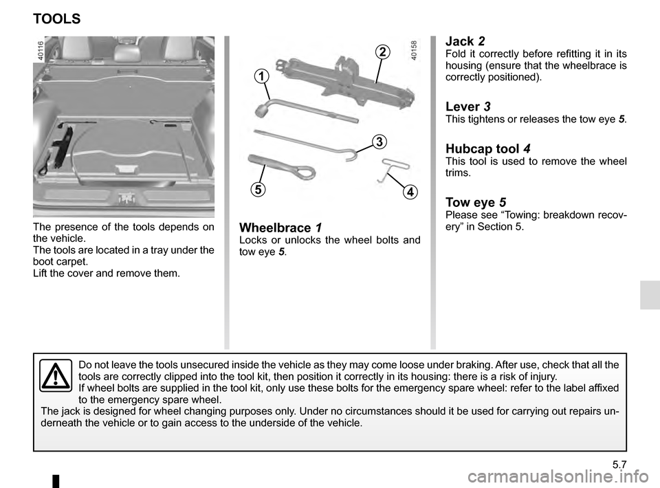
Jack 2Fold it correctly before refitting it in its
housing (ensure that the wheelbrace is
correctly positioned).
Lever 3
This tightens or releases the tow eye 5.
Hubcap tool 4This tool is used to remove the wheel
trims.
Tow eye 5Please see “Towing: breakdown recov-
ery” in Section 5.
Wheelbrace 1Locks or unlocks the wheel bolts and
tow eye 5.
The presence of the tools depends on
the vehicle.
The tools are located in a tray under the
boot carpet.
Lift the cover and remove them.
TOOLS
Do not leave the tools unsecured inside the vehicle as they may come loo\
se under braking. After use, check that all the
tools are correctly clipped into the tool kit, then position it correctl\
y in its housing: there is a risk of injury.
If wheel bolts are supplied in the tool kit, only use these bolts for th\
e emergency spare wheel: refer to the label affixed
to the emergency spare wheel.
The jack is designed for wheel changing purposes only. Under no circumstances should it be used for carrying out repairs un-
derneath the vehicle or to gain access to the underside of the vehicle.
2
1
3
45
Page 251 of 300
5.17
REAR AND SIDE LIGHTS: changing bulbs (1/3)
Side lights and brake lights
Consult an approved Dealer.
1
Refit the bulb holder and push the unit
as far as it will go, until it locks into
place.
Check that the light is properly locked
in position.
Tighten screws 2.Direction indicators 1
Open the boot lid and remove screws 2.
Pull on the outside A of the light and
remove the rear light unit.
Turn the bulb holder a quarter of a
turn 3.
Remove the bulb.
Bulb type: PY21.
2
A3