Page 120 of 448
POWER OUTLETS — IF EQUIPPED
Passenger Compartment Power Outlet
The cigar lighter and the power outlet are located in the
center console. It only operates with the ignition key at
MAR/ON.Load Compartment Power Outlet
The Load Compartment Power Outlet is located on the
left rear side of the rear cargo compartment. The outlet
can be is used for powering 12 Volt adaptive accessories
and recharging communications devices.
NOTE:
Do not connect devices with power higher than
180 W to the socket. Do not damage the socket by using
unsuitable adaptors.
Passenger Compartment Power Outlet
118 UNDERSTANDING THE FEATURES OF YOUR VEHICLE
Page 128 of 448

▫Introduction ........................ .169
▫ Recommendations .....................170
▫ Identification Number ..................171
▫ Security Code ....................... .171
▫ General ............................ .172
▫ Uconnect RH3 Display ..................173
▫ General Functions And Settings ...........174
▫ Tuner Mode (AM/FM Radio) .............177
▫ Setup Menu ........................ .180
▫ Clock ............................. .182
▫ USB Mode (MP3/WMA/AAC) ...........182
� Uconnect SETTINGS ....................190
▫ Buttons On The Faceplate ................191 ▫
Buttons On The Touchscreen ..............192
▫ Customer Programmable Features/Personal
Settings ............................ .192
� UCONNECT RADIOS ...................199
� iPod/USB/MP3 CONTROL — IF EQUIPPED . . .199
▫ USB Charging Port ....................200
� STEERING WHEEL AUDIO CONTROLS ......202
▫ Radio Operation ..................... .202
� CD DISC MAINTENANCE ...............202
� RADIO OPERATION AND MOBILE PHONES . .203
▫ General Information ...................204
� CLIMATE CONTROLS ...................204
▫ Manual Heating And Air Conditioning ......204
126 UNDERSTANDING YOUR INSTRUMENT PANEL
Page 137 of 448
Charging System Warning Light
Red TelltaleLight What It Means
Charging System Warning Light
This light shows the status of the electrical charging system. If the light stays on or comes
on while driving, turn off some of the vehicle’s nonessential electrical devices or increase
engine speed (if at idle). If the charging system light remains on, it means that the vehicle is
experiencing a problem with the charging system. Obtain SERVICE IMMEDIATELY. See an
authorized dealer.
If jump starting is required, refer to “Jump Starting Procedures” in “What To Do In Emer-
gencies.”
4
UNDERSTANDING YOUR INSTRUMENT PANEL 135
Page 202 of 448
iPod control supports Mini, 4G, Photo, Nano, 5G iPod
and iPhone devices. Some iPod software versions may
not fully support the iPod control features. Please visit
Apple’s website for software updates.
For further information, refer to the Uconnect Supple-
ment Manual.
USB Charging Port
The USB connector port can be used for charging pur-
poses only. Use the connection cable to connect an iPod
or external USB device to the vehicle’s USB charging port
which is located next to the 12V power outlet near the
cup holder on passenger side.
USB Port And AUX Jack1 — USB Port2 — AUX Audio Jack
200 UNDERSTANDING YOUR INSTRUMENT PANEL
Page 203 of 448
NOTE:If the device battery to be charged is completely
depleted, it may take awhile to charge.
WARNING!
Do not plug in or remove the iPod or external device
while driving. Failure to follow this warning could
result in a collision.
Passenger Compartment USB Charging Port
4
UNDERSTANDING YOUR INSTRUMENT PANEL 201
Page 343 of 448

3. If using another vehicle to jump-start the battery, parkthe vehicle within the jumper cables reach, set the
parking brake and make sure the ignition is OFF.
WARNING!
Do not allow vehicles to touch each other as this
could establish a ground connection and personal
injury could result.
Jump-Starting Procedure
WARNING!
Failure to follow this jump-starting procedure could
result in personal injury or property damage due to
battery explosion.
CAUTION!
Failure to follow these procedures could result in
damage to the charging system of the booster vehicle
or the discharged vehicle.
Connecting The Jumper Cables
1. Connect the positive (+)end of the jumper cable to the
remote positive (+)post of the discharged vehicle.
NOTE: The remote positive (+)post is located in the
engine compartment on the driver’s side under the cover
of the Front Power Distribution Center.
2. Connect the opposite end of the positive (+)jumper
cable to the positive (+)post of the booster battery.
3. Connect the negative end (-)of the jumper cable to the
negative (-)post of the booster battery.
6
WHAT TO DO IN EMERGENCIES 341
Page 345 of 448
If frequent jump-starting is required to start your vehicle
you should have the battery and charging system in-
spected at your authorized dealer.
CAUTION!
Accessories plugged into the vehicle power outlets
draw power from the vehicle’s battery, even when not
in use (i.e., cellular devices, etc.). Eventually, if
plugged in long enough without engine operation,
the vehicle’s battery will discharge sufficiently to
degrade battery life and/or prevent the engine from
starting.
Battery Location
There are two remote jump starting posts under the hood
which is the recommended jump start location. If access
to the battery is needed, an access panel on the driver ’s
side floor will allow for battery access.
Access Panel
6
WHAT TO DO IN EMERGENCIES 343
Page 433 of 448

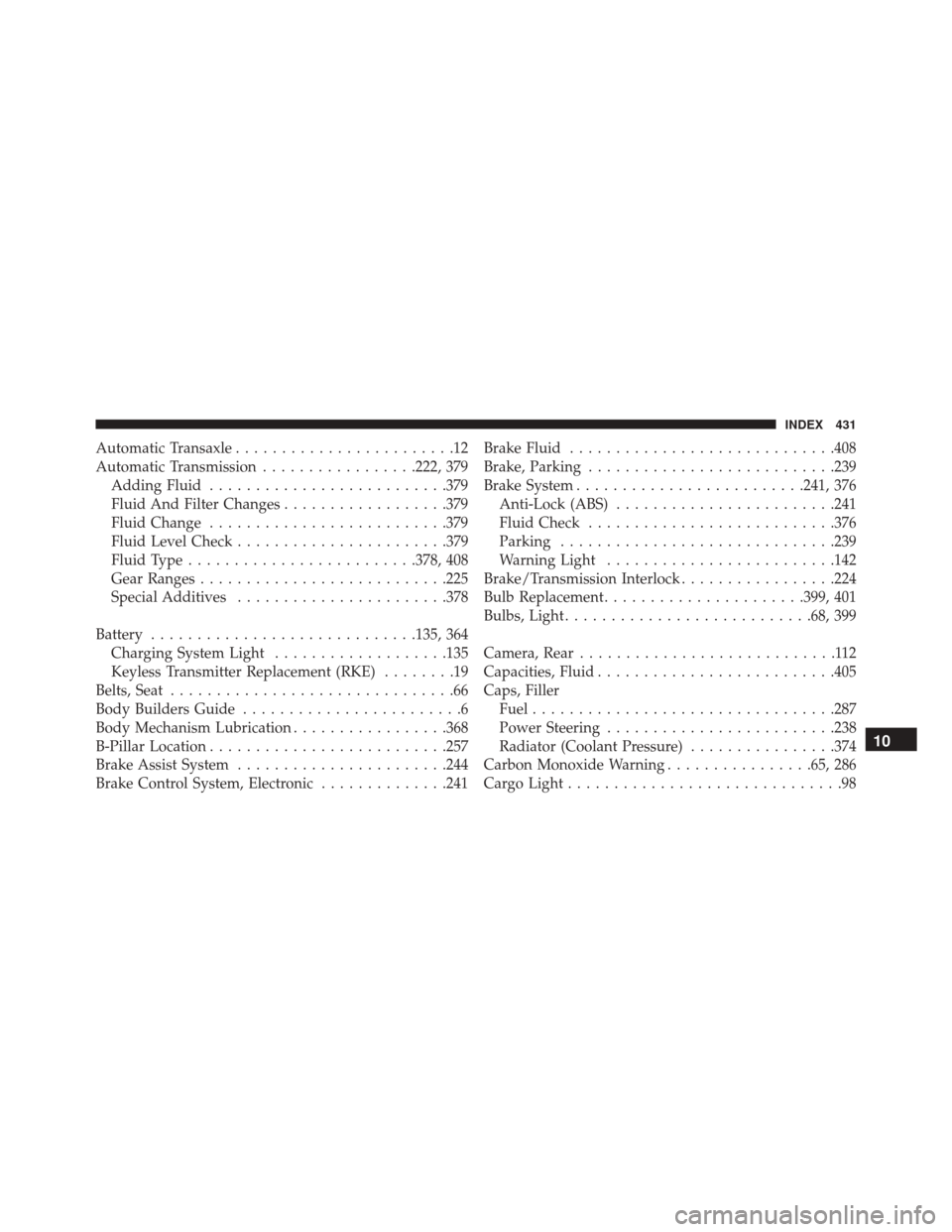
Automatic Transaxle........................12
Automatic Transmission .................222, 379
Adding Fluid ......................... .379
Fluid And Filter Changes ..................379
Fluid Change ......................... .379
Fluid Level Check ...................... .379
Fluid Type ........................ .378, 408
Gear Ranges .......................... .225
Special Additives ...................... .378
Battery ............................ .135, 364
Charging System Light ...................135
Keyless Transmitter Replacement (RKE) ........19
Belts, Seat ...............................66
Body Builders Guide ........................6
Body Mechanism Lubrication .................368
B-Pillar Location ......................... .257
Brake Assist System ...................... .244
Brake Control System, Electronic ..............241Brake Fluid
............................ .408
Brake, Parking .......................... .239
Brake System ........................ .241, 376
Anti-Lock (ABS) ....................... .241
Fluid Check .......................... .376
Parking ............................. .239
Warning Light ........................ .142
Brake/Transmission Interlock .................224
Bulb Replacement ..................... .399, 401
Bulbs, Light .......................... .68, 399
Camera, Rear ............................112
Capacities, Fluid ......................... .405
Caps, Filler Fuel ................................ .287
Power Steering ........................ .238
Radiator (Coolant Pressure) ................374
Carbon Monoxide Warning ................65, 286
Cargo Light ..............................98
10
INDEX 431