2016 Ram 2500 fuel pressure
[x] Cancel search: fuel pressurePage 281 of 406

Operating Precautions
Avoid Overheating The Engine
The temperature of the engine coolant (antifreeze) (a
mixture of 50% ethylene-glycol and 50% water) must not
exceed the normal range of the temperature gauge 240°F
(116°C) with a 21 psi (145 kPa) coolant pressure cap.
Usually the engine coolant (antifreeze) temperature indi-
cated during operation will be to the left of center in the
normal range of the gauge.
Avoid Low Coolant Temperature Operation
Continual operation at low engine coolant (antifreeze)
temperature below the normal range on the gauge 140°F
(60°C) can be harmful to the engine. Low engine coolant
(antifreeze) temperature can cause incomplete combus-
tion which allows carbon and varnish to form on pistonrings and injector nozzles. Also, the unburned fuel can
enter the crankcase, diluting the lubricating oil and
causing rapid wear to the engine.
Cooling System Tips — Automatic Transmission
To reduce potential for engine and transmission over-
heating in high ambient temperature conditions, take the
following actions:
•
City Driving —
When stopped, shift the transmission into NEUTRAL
and increase engine idle speed.
• Highway Driving —
Reduce your speed.
• Up Steep Hills —
Select a lower transmission gear.
• Air Conditioning —
Turn it off temporarily.
5
STARTING AND OPERATING 279
Page 282 of 406

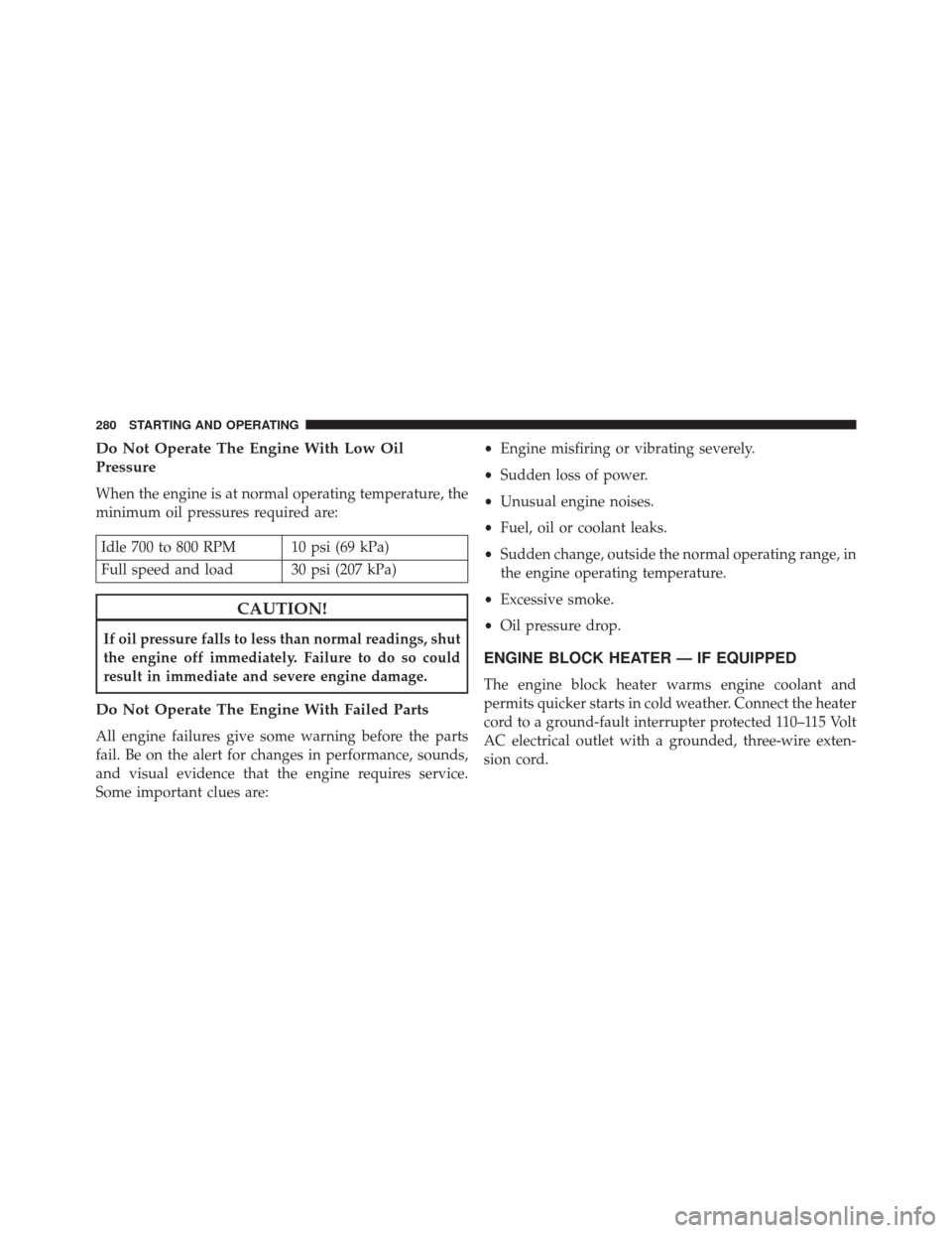
Do Not Operate The Engine With Low Oil
Pressure
When the engine is at normal operating temperature, the
minimum oil pressures required are:
Idle 700 to 800 RPM 10 psi (69 kPa)
Full speed and load 30 psi (207 kPa)
CAUTION!
If oil pressure falls to less than normal readings, shut
the engine off immediately. Failure to do so could
result in immediate and severe engine damage.
Do Not Operate The Engine With Failed Parts
All engine failures give some warning before the parts
fail. Be on the alert for changes in performance, sounds,
and visual evidence that the engine requires service.
Some important clues are:•
Engine misfiring or vibrating severely.
• Sudden loss of power.
• Unusual engine noises.
• Fuel, oil or coolant leaks.
• Sudden change, outside the normal operating range, in
the engine operating temperature.
• Excessive smoke.
• Oil pressure drop.
ENGINE BLOCK HEATER — IF EQUIPPED
The engine block heater warms engine coolant and
permits quicker starts in cold weather. Connect the heater
cord to a ground-fault interrupter protected 110–115 Volt
AC electrical outlet with a grounded, three-wire exten-
sion cord.
280 STARTING AND OPERATING
Page 319 of 406

microbes form “slime” that will clog the fuel filtration
system and lines. Drain condensation from the supply
tank and change the line filter on a regular basis.
NOTE:When a diesel engine is allowed to run out of
fuel, air is pulled into the fuel system.
If the vehicle will not start, refer to “Maintenance
Procedures/Priming If The Engine Has Run Out Of Fuel”
in “Maintaining Your Vehicle” for further information.
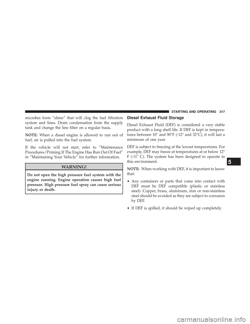
WARNING!
Do not open the high pressure fuel system with the
engine running. Engine operation causes high fuel
pressure. High pressure fuel spray can cause serious
injury or death.
Diesel Exhaust Fluid Storage
Diesel Exhaust Fluid (DEF) is considered a very stable
product with a long shelf life. If DEF is kept in tempera-
tures between 10° and 90°F (-12° and 32°C), it will last a
minimum of one year.
DEF is subject to freezing at the lowest temperatures. For
example, DEF may freeze at temperatures at or below 12°
F (-11° C). The system has been designed to operate in
this environment.
NOTE: When working with DEF, it is important to know
that:
• Any containers or parts that come into contact with
DEF must be DEF compatible (plastic or stainless
steel). Copper, brass, aluminum, iron or non-stainless
steel should be avoided as they are subject to corrosion
by DEF.
• If DEF is spilled, it should be wiped up completely.
5
STARTING AND OPERATING 317
Page 352 of 406

5. Remove lid using a socket or strap wrench. Rotatecounterclockwise for removal. Remove used o-ring
and discard it.
6. Remove the used filter cartridge from the housing and dispose of according to your local regulations.
7. Wipe clean the sealing surfaces of the lid and housing.
8. Install new o-ring back into ring groove on the filter housing and lubricate with clean engine oil.
NOTE: WIF sensor is re-usable. Service kit comes with
new o-ring for filter canister and WIF sensor.Priming If The Engine Has Run Out Of Fuel
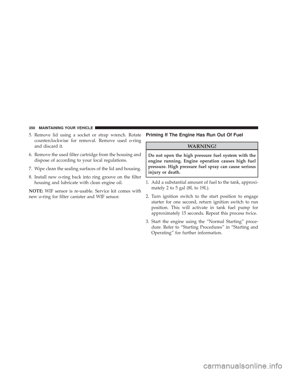
WARNING!
Do not open the high pressure fuel system with the
engine running. Engine operation causes high fuel
pressure. High pressure fuel spray can cause serious
injury or death.
1. Add a substantial amount of fuel to the tank, approxi- mately 2 to 5 gal (8L to 19L).
2. Turn ignition switch to the start position to engage starter for one second, return ignition switch to run
position. This will activate in tank fuel pump for
approximately 15 seconds. Repeat this process twice.
3. Start the engine using the “Normal Starting” proce- dure. Refer to “Starting Procedures” in “Starting and
Operating” for further information.
350 MAINTAINING YOUR VEHICLE
Page 354 of 406

•Use of biodiesel mixture in excess of 20% can nega-
tively impact the fuel filter’s ability to separate water
from the fuel, resulting in high pressure fuel system
corrosion or damage.
• Ethanol blends are not recommended or approved for
use with your Cummins diesel engine.
• In addition, commercially available fuel additives are
not necessary for the proper operation of your Cum-
mins diesel engine.
Intervention Regeneration Strategy — Message
Process Flow
The Cummins diesel engine meets all EPA Heavy Duty
Diesel Engine Emissions Standards, resulting in one of
the lowest emitting diesel engines ever produced.
To achieve these emissions standards, your vehicle is
equipped with a state-of-the-art engine and exhaust
system. The engine and exhaust after-treatment system work together to achieve the EPA Heavy Duty Diesel
Engine Emissions Standards. These systems are seam-
lessly integrated into your vehicle and managed by the
Cummins Powertrain Control Module (PCM). The PCM
manages engine combustion to allow the exhaust sys-
tem’s catalyst to trap and burn Particulate Matter (PM)
pollutants, with no input or interaction on your part.
Additionally, your vehicle has the ability to alert you to
additional maintenance required on your truck or engine.
Refer to “Electronic Vehicle Information Center (EVIC)”
or “Driver Information Display (DID)” in “Understand-
ing Your Instrument Panel” for further information.
WARNING!
A hot exhaust system can start a fire if you park over
materials that can burn. Such materials might be
(Continued)
352 MAINTAINING YOUR VEHICLE
Page 362 of 406

•Do not change the thermostat for Summer or Winter
operation. If replacement is ever necessary, install
ONLY the correct type thermostat. Other designs may
result in unsatisfactory engine coolant (antifreeze)
performance, poor gas mileage, and increased emis-
sions.
Charge Air Cooler — Inter-Cooler
The charge air cooler is positioned below the radiator and
the air conditioner condenser. Air enters the engine
through the air cleaner and passes through the turbo-
charger, where it is pressurized. This pressurized air
rapidly reaches high temperature. The air is then directed
through a hose to the charge air cooler and through
another hose to the intake manifold of the engine. The air
entering the engine has been cooled by about 50° to 100°F
(10° to 38°C). This cooling process enables more efficient
burning of fuel resulting in fewer emissions. To guarantee optimum performance of the system, keep
the surfaces of the charge air cooler, condenser and
radiator clean and free of debris. Periodically check the
hoses leading to and from the charge air cooler for cracks
or loose clamps resulting in loss of pressure and reduced
engine performance.
Brake System
Brake Master Cylinder — Brake Fluid Level Check
The fluid level of the master cylinder should be checked
when performing under the hood service, or immedi-
ately if the “Brake System Warning Light” indicates
system failure.
The brake master cylinder has a translucent plastic
reservoir. On the outboard side of the reservoir, there is a
“MAX” mark and a “MIN” mark. The fluid level must be
kept within these two marks. Do not add fluid above the
full mark because leakage may occur at the cap.
360 MAINTAINING YOUR VEHICLE
Page 394 of 406

Adding Engine Coolant (Antifreeze)............140
Adding Fuel .............................114
Air Bag Light .............................25
Air Cleaner, Engine (Engine Air Cleaner Filter) . . . .128
Alarm (Security Alarm) ......................28
Antifreeze (Engine Coolant) ..................139
Capacities ........................... .146
Disposal ............................. .142
Automatic Transmission Fluid Type ........................... .150
Axle Fluid ............................. .150
Battery .................................30
Charging System Light ....................30
Brake Fluid ............................ .150
Brake System ........................... .144
Fluid Check .......................... .144
Master Cylinder ....................... .144Warning Light
..........................26
Capacities, Antifreeze (Engine Coolant) ..........146
Capacities, Fluid ......................... .146
Caps, Filler Oil (Engine) .......................... .127
Radiator (Coolant Pressure) ................142
Charge Air Cooler ........................ .144
Coolant Pressure Cap (Radiator Cap) ...........142
Cooling System .......................... .138
Adding Coolant (Antifreeze) ...............140
Coolant Capacity ...................... .146
Coolant Level ......................... .138
Disposal Of Used Coolant .................142
Drain, Flush, And Refill ...................139
Points To Remember .....................143
Pressure Cap ......................... .142
Radiator Cap ......................... .142
Selection Of Coolant (Antifreeze) ........139 , 147
8
INDEX - RAM 1500 391
Page 396 of 406

Fuel.................................. .108
Adding ..............................114
Diesel ........................... .108 , 147
Filter ............................... .131
Light .................................43
Requirements ......................... .108
Specifications ......................... .109
Tank Capacity ......................... .146
Fueling .................................114
Gauges Voltmeter ............................ .102
Information Center, Vehicle ...................63
Instrument Cluster .........................17
Intervention Regeneration Strategy ..............71
Keyless Enter-N-Go ........................99 Lights
AirBag ...............................25
Brake Warning ..........................26
Cruise .............................58,60
Engine Temperature Warning ................29
Fog ..................................46
Low Fuel ..............................43
Malfunction Indicator (Check Engine) ..........36
Park ..............................56,58
Seat Belt Reminder .......................24
Security Alarm ..........................28
Tire Pressure Monitoring (TPMS) .............40
Turn Signal ............................57
Warning (Instrument Cluster Description) . . . .29 , 57
Maintenance Procedures ....................125
Maintenance Schedule ..................... .152
Malfunction Indicator Light (Check Engine) .......36
8
INDEX - RAM 1500 393