2016 Peugeot 508 RXH spare wheel
[x] Cancel search: spare wheelPage 228 of 364
226
508_en_Chap07_info-pratiques_ed01-2016
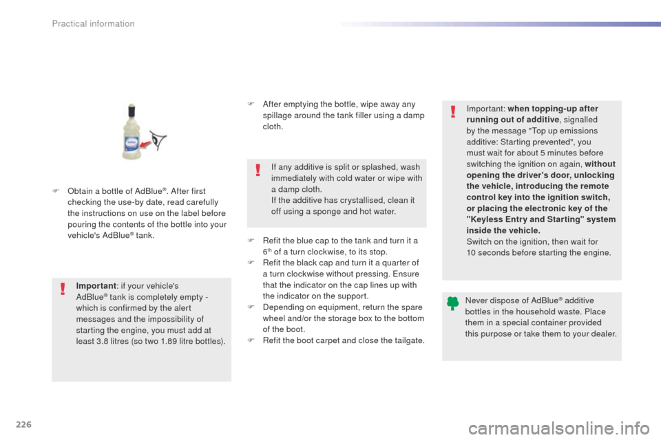
F Obtain a bottle of AdBlue®. After first
checking the use-by date, read carefully
the instructions on use on the label before
pouring the contents of the bottle into your
vehicle's AdBlue
® tank.
Important : if your vehicle's
AdBlue
® tank is completely empty -
w
hich is confirmed by the alert
messages and the impossibility of
starting the engine, you must add at
least 3.8 litres (so two 1.89 litre bottles). F
A
fter emptying the bottle, wipe away any
spillage around the tank filler using a damp
cloth.
If any additive is split or splashed, wash
immediately with cold water or wipe with
a damp cloth.
If the additive has crystallised, clean it
off using a sponge and hot water.
F
R
efit the blue cap to the tank and turn it a
6
th of a turn clockwise, to its stop.
F
R
efit the black cap and turn it a quarter of
a turn clockwise without pressing.
e
n
sure
that the indicator on the cap lines up with
the indicator on the support.
F
D
epending on equipment, return the spare
wheel and/or the storage box to the bottom
of the boot.
F
R
efit the boot carpet and close the tailgate. Important: when topping-up after
running out of additive
, signalled
by the message "
to
p up emissions
additive: Starting prevented", you
must wait for about 5 minutes before
switching the ignition on again, without
opening the driver's door, unlocking
the vehicle, introducing the remote
control key into the ignition switch,
or placing the electronic key of the
"Keyless Entr y and Star ting" system
inside the vehicle.
Switch on the ignition, then wait for
10 seconds before starting the engine.
Never dispose of AdBlue
® additive
bottles in the household waste. Place
them in a special container provided
this purpose or take them to your dealer.
Practical information
Page 237 of 364
235
508_en_Chap08_en-cas-de-pannes_ed01-2016
Spare wheel
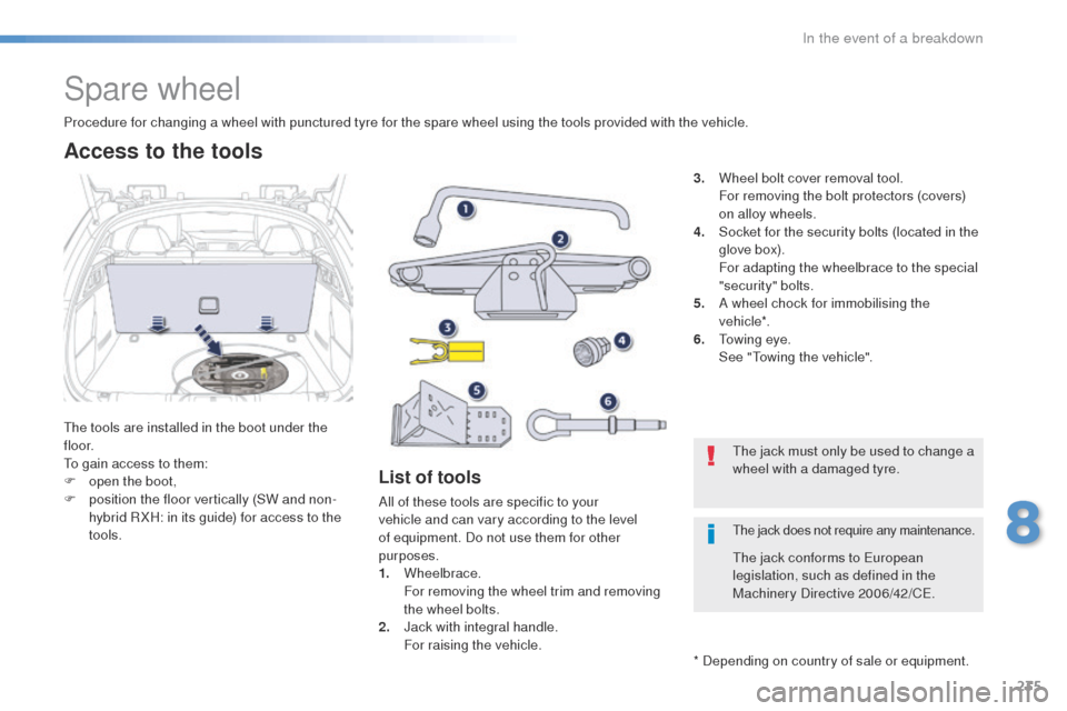
the tools are installed in the boot under the
f l o o r.
to g
ain access to them:
F
o
pen the boot,
F
p
osition the floor vertically (SW and non-
hybrid R XH: in its guide) for access to the
tools.
Procedure for changing a wheel with punctured tyre for the spare wheel using the tools provided with the vehicle.
List of tools
All of these tools are specific to your
vehicle and can vary according to the level
of equipment. Do not use them for other
purposes.
1.
Wheelbrace.
F
or removing the wheel trim and removing
the wheel bolts.
2.
J
ack with integral handle.
F
or raising the vehicle. 3.
W
heel bolt cover removal tool.
F
or removing the bolt protectors (covers)
on alloy wheels.
4.
S
ocket for the security bolts (located in the
glove box).
F
or adapting the wheelbrace to the special
"security" bolts.
5.
A w
heel chock for immobilising the
vehicle*.
6.
t
o
wing eye.
S
ee "
to
wing the vehicle".
Access to the tools
* Depending on country of sale or equipment.
th
e jack must only be used to change a
wheel with a damaged tyre.
th
e jack conforms to e
u
ropean
legislation, such as defined in the
Machinery Directive 2006/42/C
e.
the jack does not require any maintenance.
8
In the event of a breakdown
Page 238 of 364
236
508_en_Chap08_en-cas-de-pannes_ed01-2016
Wheel with wheel trim
When refitting the wheel, refit the trim
starting by placing its notch facing the
valve and press around its edge with
the palm of your hand.
th
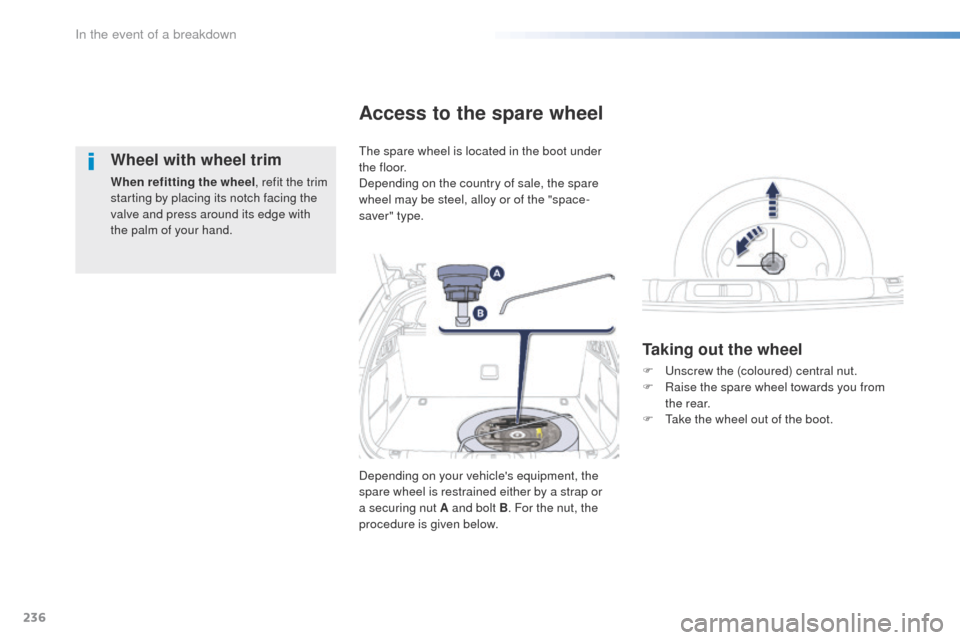
e spare wheel is located in the boot under
t h e f l o o r.
Depending on the country of sale, the spare
wheel may be steel, alloy or of the "space-
saver" type.
Access to the spare wheel
Taking out the wheel
Depending on your vehicle's equipment, the
spare wheel is restrained either by a strap or
a securing nut A and bolt B . For the nut, the
procedure is given below. F
u
n
screw the (coloured) central nut.
F
R
aise the spare wheel towards you from
the rear.
F t
a
ke the wheel out of the boot.
In the event of a breakdown
Page 239 of 364

237
508_en_Chap08_en-cas-de-pannes_ed01-2016
Putting the wheel back in place
F Put the box back in place in the centre of the wheel and clip it.
F
P
ut the polystyrene storage box back in
place.
F
P
ut the wheel back in its housing.
F
un
screw the (coloured) central nut by a few
turns then put it in place in the centre of the
wheel.
F
t
i
ghten fully until the central bolt clicks to
retain the wheel correctly.Tyre under-inflation detection
the space-saver type or steel spare
wheel does not have a sensor.
th
e punctured wheel must be repaired
by a P
e
uge
Ot
dealer or a qualified
workshop.
8
In the event of a breakdown
Page 241 of 364

239
508_en_Chap08_en-cas-de-pannes_ed01-2016
F Raise the vehicle until there is sufficient space between the wheel and the ground
to admit the spare (not punctured) wheel
easily.
F
R
emove the bolts and store them in a clean
place.
F
R
emove the wheel.
F
e
x
tend the jack 2 until its head comes into
contact with the jacking point A or B used;
the vehicle's contact sur face at A or B must
engage with the central part of the head of
the jack.
en
sure that the jack is stable. If the
ground is slippery or loose, the jack
might slip or drop - Risk of injury!
ta
ke care to position the jack only at
one of the vehicle's jacking points A
or B under the vehicle, ensuring that the
contact sur face of the vehicle's jacking
point is centred on the head of the jack.
Otherwise there is a risk of damage to
the vehicle and/or that the jack might
drop - Risk of injury!
8
In the event of a breakdown
Page 242 of 364
240
508_en_Chap08_en-cas-de-pannes_ed01-2016
Fitting a wheel
Fitting the "space-saver"
spare wheel
If your vehicle is fitted with alloy wheels,
when tightening the bolts on fitting, it
is normal to notice that the washers
do not come into contact with the
"space-saver" spare wheel. t
h
e wheel
is secured by the conical sur face of
each bolt.
After changing a wheel
to store the punctured wheel in the
boot correctly, first remove the central
c ove r.
When using the "space-saver" type
spare wheel, do not exceed 50 mph
(80
km/h).
Have the tightening of the bolts and the
pressure of the spare wheel checked
by a P
e
uge
Ot
dealer or a qualified
workshop without delay.
Have the punctured wheel repaired
and refitted to the vehicle as soon as
possible. F
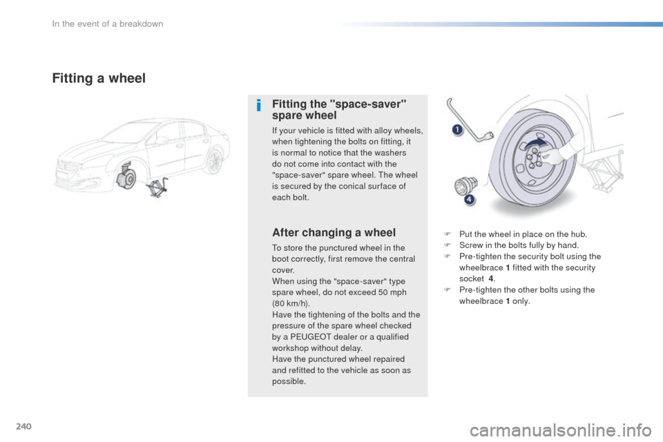
P
ut the wheel in place on the hub.
F S crew in the bolts fully by hand.
F P re-tighten the security bolt using the
wheelbrace 1 fitted with the security
socket
4.
F
P
re-tighten the other bolts using the
wheelbrace 1 o n l y.
In the event of a breakdown
Page 275 of 364

273
508_en_Chap09_caracteristiques-techniques_ed01-2016
Identification markingsVarious visible markings for the identification of your vehicle.
A.
V
ehicle Identification Number (VIN)
under the bonnet.
t
h
is number is engraved on the bodywork
near the damper mounting.
th
e tyre pressures must be checked
when the tyres are cold, at least once
a month.
Low tyre pressures increase fuel
consumption.
B.
V
ehicle identification Number (VIN) on
the windscreen lower crossmember.
t
h
is number is given on a self-adhesive
label which is visible through the
windscreen. C.
M
anufacturer's label.
t
h
e VIN is marked on a self-destroying
label affixed to the door aperture, on the
driver's side.
D.
T
yre/paint label.
t
h
is label is fitted to the middle pillar, on
the driver's side. It bears the following information:
-
t
he tyre inflation pressures with and without
load,
-
t
he tyre sizes,
-
t
he inflation pressure of the spare wheel,
-
t
he paint colour code.
9
technical data
Page 359 of 364
357
508_en_Chap11_index-alpha_ed01-2016
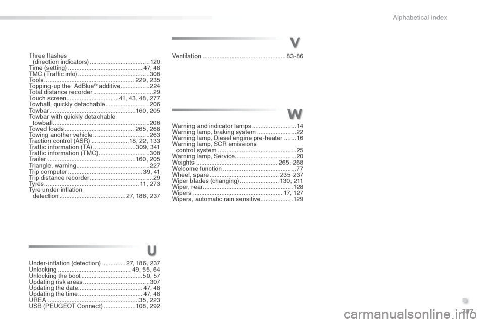
three flashes (direction indicators) ...................................120
tim
e (setting)
..............................
..............4 7, 4 8
tM
C (
tr
affic info)
.......................................... 3
08
to
o l s
..................................................... 229, 235
to
pping-up the AdBlue
® additive ................. 2 24to
tal distance recorder
................................... 29
to
uch screen ...............................41, 43, 48, 277
to
wball, quickly detachable
.......................... 206
to
w b a r
................................................... 160, 205
to
wbar with quickly detachable
towball
......................................................... 206
to
wed loads
......................................... 265, 268
to
wing another vehicle
................................. 26
3
tra
ction control (ASR)
...................... 18, 22, 133
tr
affic information (
tA
)
......................... 3 0 9 , 3 41
tr
affic information (
tM
C)
.............................. 3
08
t
r a i l e r
.................................................... 160, 205
tr
iangle, warning ........................................... 227
tr
ip computer
............................................ 3 9 , 41
tr
ip distance recorder
..................................... 29
ty
r e s
........................................................ 11, 2 7 3
ty
re under-inflation
detection
....................................... 27, 186, 237Ventilation
..............................
...................
83-86
V
Warning and indicator lamps ..........................14
Warning lamp, braking system .......................22
Warning lamp, Diesel engine pre-heater
.......16
Warning lamp, SCR emissions control system
.............................................. 25
W
arning lamp, Service .................................... 20
Weights
................................................ 265, 268
Welcome function
........................................... 77
Wheel, spare
......................................... 235-237
Wiper blades (changing)
....................... 1
3 0 , 2 11
Wiper, rear ..................................................... 128
Wipers
..................................................... 17, 1 2 7
Wipers, automatic rain sensitive
...................129
W
U
under-inflation (detection) ..............2 7, 186, 237unl
ocking .............................. .............49, 55, 64
un
locking the boot .................................... 50, 57
up
dating risk areas
....................................... 3
07
up
dating the date
...................................... 4 7, 4 8
upd
ating the time
...................................... 4 7, 4 8
uR
e
A
...................................................... 35, 223
uS
B (Peuge
O
t Connect)
................... 10
8, 292
.
Alphabetical index