Page 162 of 364

160
508_en_Chap06_conduite_ed01-2016
When towing
Distribution of loads
F Distribute the load in the trailer so that the heaviest items are as close as possible to
the axle and the nose weight approaches
the maximum permitted without
exceeding
it.
Air density decreases with altitude, thus
reducing engine performance. Above
1
000 metres, the maximum towed load must
be reduced by 10
% for every 1 000 metres of
altitude.
Side wind
F take into account the increased sensitivity to side wind.
Cooling
towing a trailer on a slope increases the
temperature of the coolant.
As the fan is electrically controlled, its cooling
capacity is not dependent on the engine speed.
F
t
o l
ower the engine speed, reduce your
speed.
th
e maximum towed load on a long incline
depends on the gradient and the ambient
temperature.
In all cases, keep a check on the coolant
temperature.
F
I
f the warning lamp and the
STOP warning lamp come on,
stop the vehicle and switch off
the engine as soon as possible.
Braking
towing a trailer increases the braking distance.to a void overheating of the brakes, the use of
engine braking is recommended.
Ty r e s
F Check the tyre pressures of the towing vehicle and of the trailer, observing the
recommended pressures.
Lighting
F Check the electrical lighting and signalling on the trailer and the hadlamp beam height
of your vehicle.
For more information on adjusting the
headlamp beam height, refer to the
corresponding section.
th
e rear parking sensors will be
deactivated automatically if a genuine
P
e
uge
Ot
towbar is used.
For more information on weights (and
the towed loads which apply to your
vehicle) refer to the corresponding
section.
Driving
Page 167 of 364

165
508_en_Chap06_conduite_ed01-2016
For Diesel vehicles, in very cold
weather the engine will not start
until the pre-heater warning
lamp has gone off.
If this warning lap comes on
after pressing the "S TA R T/
STOP " button, you should
maintain pressure on the brake
or clutch pedal until the warning
lamp goes off and not press the
" START/STOP " button, until the
engine starts. If the vehicle is not immobilised, the
engine will not stop.
Switching off
F Immobilise the vehicle.
F
W
ith the electronic key inside
the vehicle, press the " S TA R T/
STOP " button.
th
e engine stops and the steering column is
locked.
Ignition on (accessory) position
With the electronic key inside the vehicle,
press the "StA Rt/ StO P" button, with no
action on the pedals, to switch the ignition
on or off and so allow the use of the ancillary
equipment.
If one of the starting conditions is not
met, a reminder message appears in
the instrument panel screen. In some
circumstances, it is necessary to turn
the steering wheel slightly while pressing
the "S
tA
R
t/
S
tO
P" button to assist
unlocking of the steering; a message
warns you when this is needed.
F
W
ith the electronic key inside the vehicle,
press the brake pedal on vehicles with
automatic gearbox, or depress the clutch
pedal fully on vehicles with a manual
gearbox, then maintain pressure until the
engine starts.
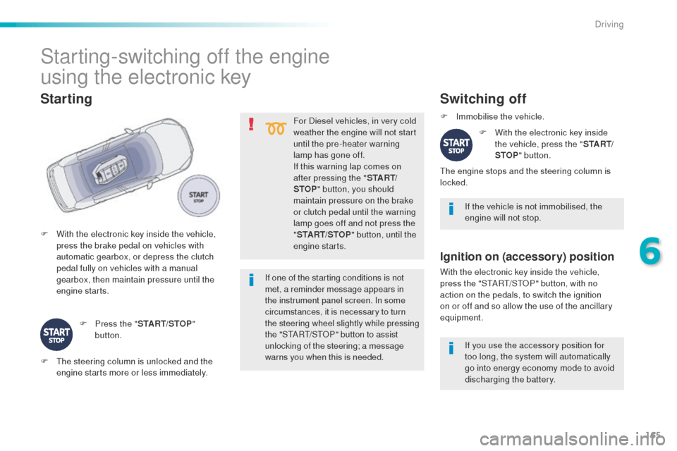
Starting
F Press the " START/STOP"
button.
Starting-switching off the engine
using the electronic key
F the steering column is unlocked and the engine starts more or less immediately. If you use the accessory position for
too long, the system will automatically
go into energy economy mode to avoid
discharging the battery.
6
Driving
Page 173 of 364
171
508_en_Chap06_conduite_ed01-2016
Emergency braking
In the event of a failure of the main service brake, a
continuous pull on the control lever A will stop the
vehicle.
th
e dynamic stability control provides stability
during emergency braking.
If the emergency braking malfunctions, the message
"Parking brake control faulty" will be displayed.
If a failure of the DSC system is
signalled by the lighting of this
warning lamp, then braking stability is
not guaranteed.
th
e emergency braking must only be
used in exceptional circumstances. In the event of a battery failure, the
parking brake can no longer be
operated.
As a safety measure, if the parking
brake is not applied, immobilise the
vehicle by engaging a gear or by
placing a chock against one of the
wheels.
Contact a Pe
ugeOt dealer or a
qualified workshop.
In this event, stability must be assured by the
driver by repeating alternate "pull-release"
actions on the control lever A .
6
Driving
Page 182 of 364

180
508_en_Chap06_conduite_ed01-2016
Stop & Start
Operation
Going into engine STOP mode
the "ECO" indicator lamp comes
on in the instrument panel and the
engine goes into standby:
-
w
ith a manual gearbox, at speeds below
12 mph (20 km/h), or vehicle stationary
with the e-
tH
P 165 version, when you put
the gear lever into neutral and release the
clutch pedal,
-
w
ith an automatic gearbox, vehicle
stationary, when you press the brake pedal
or you put the gear selector in position N .
If your vehicle is fitted with the system, a time
counter calculates the sum of the periods in
S
tO
P mode during a journey. It rests itself to
zero every time the ignition is switched on with
t h e key. Never refuel with the engine in
S
tO
P mode; you must switch off the
ignition with the key. For your comfort, during parking
maoeuvres, S
tO
P mode is not
available for a few seconds after
coming out of reverse gear.
S
tO
P mode does not affect the
functionality of the vehicle, such as for
example, braking, power steering...
th
e Stop & Start
system puts the engine
temporarily into standby - S
tO
P mode -
during stops in the traffic (red lights, traffic
jams, or other...).
t
h
e engine restarts
automatically
-
StA
Rt
mode - as soon as
you want to move off.
th
e restart takes place
instantly, quickly and silently.
Per fect for urban use, the Stop & Start system
reduces fuel consumption and exhaust
emissions as well as the noise level when
stationary.
Driving
Page 224 of 364

222
508_en_Chap07_info-pratiques_ed01-2016
Manual gearbox
the gearbox does not require any
maintenance (no oil change).
Refer to the manufacturer's service
schedule for the checking interval
for this component.
Automatic gearbox
the gearbox does not require any
maintenance (no oil change).
Refer to the manufacturer's
service schedule for details of
the level checking interval for this
component.
Brake wear depends on the style
of driving, particularly in the case
of vehicles used in town, over short
distances. It may be necessary to
have the condition of the brakes checked, even
between vehicle services.
un
less there is a leak in the circuit, a drop in
the brake fluid level indicates that the brake
pads are worn.
Brake pads
For information on checking brake
disc wear, contact a Pe ugeOt
dealer or a qualified workshop.
Brake disc wear Electric parking brake
this system does not require any
routine servicing. However, in
the event of a problem, have the
system checked by a P
e
uge
Ot
dealer or a qualified workshop.
Only use products recommended by
P
e
uge
Ot
or products of equivalent
quality and specification.
In order to optimise the operation of
units as important as those in the
braking system, P
e
uge
Ot
selects and
offers very specific products.
After washing the vehicle, dampness,
or in wintry conditions, ice can form
on the brake discs and pads: braking
efficiency may be reduced. Make light
brake applications to dry and defrost
the brakes.
Parking brake
If excessive travel or a loss of
effectiveness of this system is
noticed, the parking brake must
be checked, even between
two
services.
Checking this system must be done by a
P
e
uge
Ot
dealer or a qualified workshop. For more information on the electric parking
brake, refer to the corresponding section.
Practical information
Page 247 of 364

245
508_en_Chap08_en-cas-de-pannes_ed01-2016
1. Brake lamps
( light emitting diodes - LEDs).
2.
Si
delamps
(
light emitting diodes - LEDs).
3.
D
irection indicators
(
PY21W amber).
4.
Fo
glamps
(
light-emitting diodes) /
R
eversing lamps (W16W).
Rear lamps (Saloon)
Direction indicators and reversing lamp
Direction indicators Reversing lamp
Light emitting diodes-LEDs
For replacement, contact a PeugeOt
dealer or qualified workshop. F
O
pen the boot, then the plastic cover.
F
R
emove the two lamp unit fixing nuts.
F e
x
tract the lamp unit carefully from the
outside.
F
D
isconnect the electrical connector.
F
S
pread the tabs and remove the bulb
h o l d e r.
F t
u
rn the bulb a quarter of a turn and pull it
out.
For reassembly, carry out these operations in
reverse order. -
R
emove the direction indicator bulb holder,
as described above.
- t
u
rn the bulb a quarter of a turn and
change it.to r eassemble, carry out these operations in
reverse order.
8
In the event of a breakdown
Page 248 of 364
246
508_en_Chap08_en-cas-de-pannes_ed01-2016
1. Brake lamps (light emitting diodes - LEDs).
2.
R
eversing lamps (W19W).
3.
D
irection indicators (PY21W amber).
4.
S
idelamps (light emitting diodes -
LEDs).
5.
F
oglamps (light emitting diodes - LEDs).
Rear lamps (SW and non-hybrid RXH)
F Open the boot then remove the access c ove r.
F
R
emove the sealing foam.
F
D
isconnect the lamp connector.
F
R
emove the lamp fixing nut.
Direction indicators
(on the wings)
F Carefully remove the lamp unit from
outside.
F
R
emove the sealing foam.
F
u
n
clip the bulb holder.
F
t
u
rn the bulb a quarter of a turn and pull
it
out.
For reassembly, carry out these operations in
reverse order.
Light emitting diodes-LEDs
For replacement, contact a Pe ugeOt
dealer or qualified workshop.
In the event of a breakdown
Page 250 of 364
248
508_en_Chap08_en-cas-de-pannes_ed01-2016
Third brake lamp (light emitting
diodes - LEDs)
Contact a PeugeOt dealer or qualified
workshop.
Number plate lamps
F Insert a thin screwdriver into one of the outer holes of the lens.
F
P
ush it outwards to unclip.
F
D
isconnect the lamp connector.
F
R
emove the lens.
F
P
ull the bulb out and change it.
In the event of a breakdown