Page 136 of 636
Choose the appropriate method to signal a lane
change based on road and traffic conditions.
For additional information on disabling the 3 flash
pass turn indicator, refer to “How to use the
vehicle information display” in “Vehicle informa-
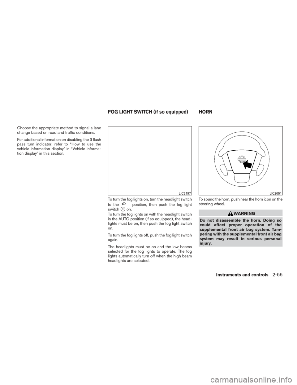
tion display” in this section.To turn the fog lights on, turn the headlight switch
to the
position, then push the fog light
switch
�1on.
To turn the fog lights on with the headlight switch
in the AUTO position (if so equipped) , the head-
lights must be on, then push the fog light switch
on.
To turn the fog lights off, push the fog light switch
again.
The headlights must be on and the low beams
selected for the fog lights to operate. The fog
lights automatically turn off when the high beam
headlights are selected. To sound the horn, push near the horn icon on the
steering wheel.WARNING
Do not disassemble the horn. Doing so
could affect proper operation of the
supplemental front air bag system. Tam-
pering with the supplemental front air bag
system may result in serious personal
injury.
LIC2197LIC2051
FOG LIGHT SWITCH (if so equipped) HORN
Instruments and controls2-55
Page 148 of 636
12V OUTLETS
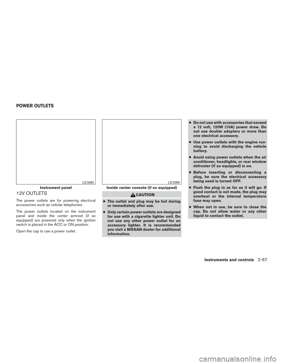
The power outlets are for powering electrical
accessories such as cellular telephones.
The power outlets located on the instrument
panel and inside the center armrest (if so
equipped) are powered only when the ignition
switch is placed in the ACC or ON position.
Open the cap to use a power outlet.
CAUTION
●The outlet and plug may be hot during
or immediately after use.
● Only certain power outlets are designed
for use with a cigarette lighter unit. Do
not use any other power outlet for an
accessory lighter. It is recommended
you visit a NISSAN dealer for additional
information. ●
Do not use with accessories that exceed
a 12 volt, 120W (10A) power draw. Do
not use double adapters or more than
one electrical accessory.
● Use power outlets with the engine run-
ning to avoid discharging the vehicle
battery.
● Avoid using power outlets when the air
conditioner, headlights, or rear window
defroster (if so equipped) is on.
● Before inserting or disconnecting a
plug, be sure the electrical accessory
being used is turned OFF.
● Push the plug in as far as it will go. If
good contact is not made, the plug may
overheat or the internal temperature
fuse may open.
● When not in use, be sure to close the
cap. Do not allow water or any other
liquid to contact the outlet.
Instrument panel
LIC3383
Inside center console (if so equipped)
LIC3385
POWER OUTLETS
Instruments and controls2-67
Page 151 of 636
Do not use the outlet located in the truck box with
accessories that exceed 120 volt. Do not use
double adapters or more than one electrical ac-
cessory. When the dual wall bed liner is installed
(if so equipped) , the power outlet is still acces-
sible through the access door in the bed liner.
CAUTION
●Operation of the 120 volt system with
the ignition in the ON position and the
engine not running (idle) will drain the
battery charge. This could lead to a
dead battery or no start condition.
● The outlet and plug may be hot during
or immediately after use.
● Use power outlets with the engine run-
ning to avoid discharging the vehicle
battery.
● Do not use double adaptors or more
than one electrical accessory.
● Avoid using power outlets when the air
conditioner, headlights or rear window
defroster is on.
● Before inserting or disconnecting a
plug, be sure the electrical accessory
being used is turned OFF. ●
Push the plug in as far as it will go. If
good contact is not made, the plug may
overheat or the internal temperature
fuse may open.
● When not in use, be sure to close the
cap. Do not allow water or any other
liquid to contact the outlet.
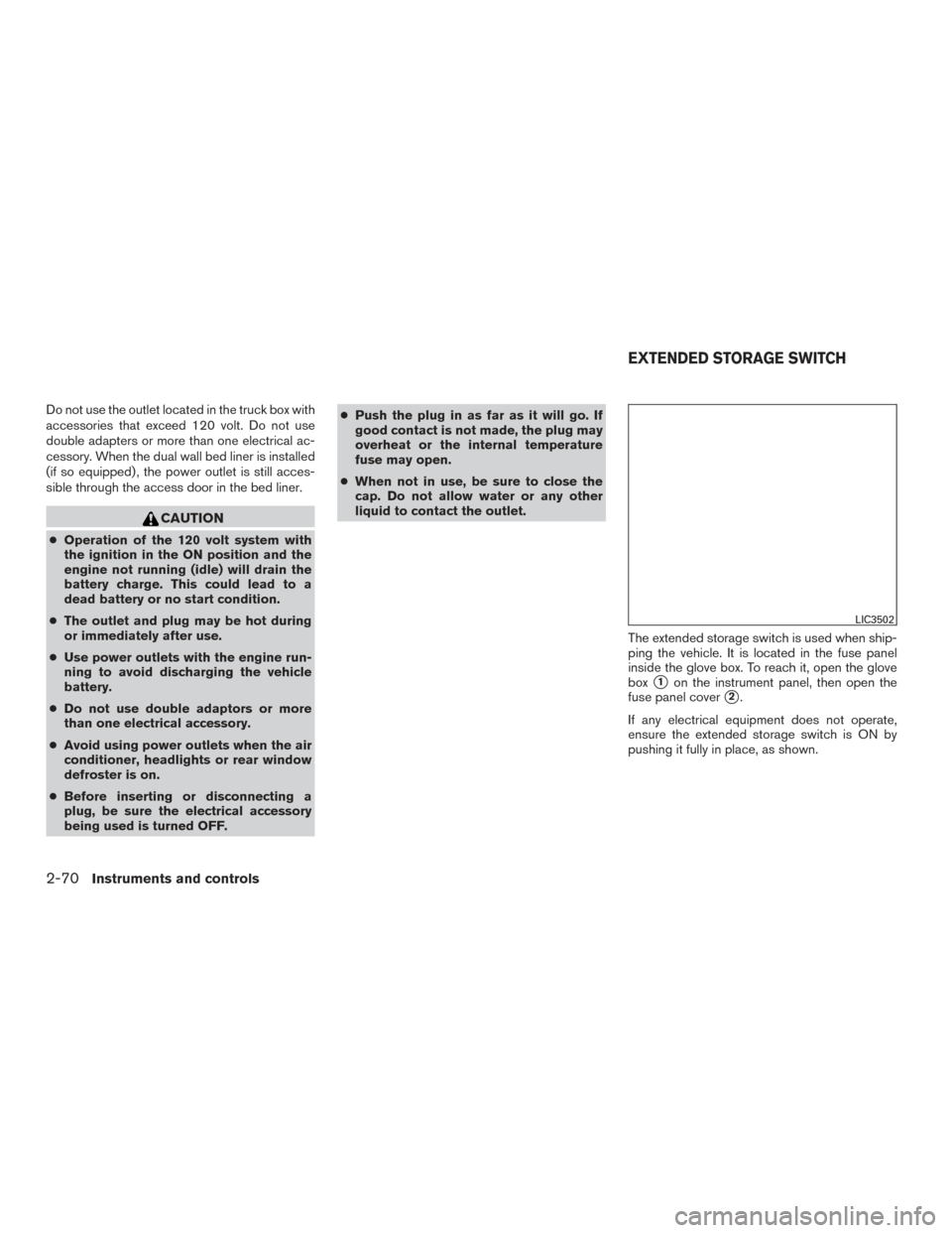
The extended storage switch is used when ship-
ping the vehicle. It is located in the fuse panel
inside the glove box. To reach it, open the glove
box
�1on the instrument panel, then open the
fuse panel cover
�2.
If any electrical equipment does not operate,
ensure the extended storage switch is ON by
pushing it fully in place, as shown.
LIC3502
EXTENDED STORAGE SWITCH
2-70Instruments and controls
Page 166 of 636
NOTE:
The door step lights (if so equipped) illumi-
nate when the driver and passenger doors
are open regardless of the interior light
switch position. These lights will turn off
automatically after a period of time while
doors are open to prevent the battery from
becoming discharged.
CAUTION
Do not use for extended periods of time
with the engine stopped. This could result
in a discharged battery.
CONSOLE LIGHT (if so equipped)
The console light will turn on whenever the park-
ing lights or headlights are illuminated.
The console light brightness can be adjusted
with the illumination brightness control.
MAP LIGHTS (if so equipped)
To turn the map lights on, push the switches. To
turn them off, push the switches again.
CAUTION
Do not use for extended periods of time
with the engine stopped. This could result
in a discharged battery.
LIC3405LIC0790
Instruments and controls2-85
Page 186 of 636
Using the panic alarm
If you are near your vehicle and feel threatened,
you may activate the panic alarm to call attention
by pressing and holding the
button on the
Intelligent Key for longer than 1 second.
The panic alarm and headlights will stay on for a
period of time. The panic alarm stops when:
● It has run for a period of time, or
● Any button is pressed on the Intelligent Key.
● The request switch (if so equipped) on the
driver’s door is pushed and the Intelligent
Key is in range of the door handle.
Trailer light check (if so equipped)
This functionality allows the customer to confirm
trailer light operation, without the need of a sec-
ond person to press the brake pedal or activate
each turn signal light. The trailer light check can
be performed by the Intelligent Key or through the
Vehicle Settings in the vehicle information dis-
play. For additional information, refer to “Vehicle
information display” in the “Instruments and con-
trols” section of this manual.
WPD0374LPD2257
Pre-driving checks and adjustments3-15
Page 198 of 636
CARD HOLDER (driver’s side only)
To access the card holder, slide card in the card
holder. Do not view information while operating
the vehicle.
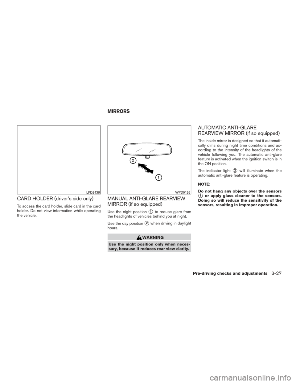
MANUAL ANTI-GLARE REARVIEW
MIRROR (if so equipped)
Use the night position�1to reduce glare from
the headlights of vehicles behind you at night.
Use the day position
�2when driving in daylight
hours.
WARNING
Use the night position only when neces-
sary, because it reduces rear view clarity.
AUTOMATIC ANTI-GLARE
REARVIEW MIRROR (if so equipped)
The inside mirror is designed so that it automati-
cally dims during night time conditions and ac-
cording to the intensity of the headlights of the
vehicle following you. The automatic anti-glare
feature is activated when the ignition switch is in
the ON position.
The indicator light
�2will illuminate when the
automatic anti-glare feature is operating.
NOTE:
Do not hang any objects over the sensors
�1or apply glass cleaner to the sensors.
Doing so will reduce the sensitivity of the
sensors, resulting in improper operation.LPD2436WPD0126
MIRRORS
Pre-driving checks and adjustments3-27
Page 202 of 636
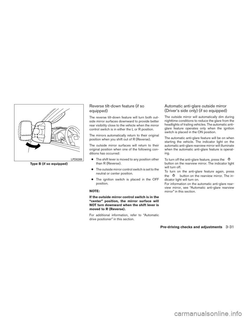
Reverse tilt-down feature (if so
equipped)
The reverse tilt-down feature will turn both out-
side mirror surfaces downward to provide better
rear visibility close to the vehicle when the mirror
control switch is in either the L or R position.
The mirrors automatically return to their original
position when you shift out of R (Reverse) .
The outside mirror surfaces will return to their
original position when one of the following con-
ditions has occurred:● The shift lever is moved to any position other
than R (Reverse) .
● The outside mirror control switch is set to the
neutral or center position.
● The ignition switch is placed in the OFF
position.
NOTE:
If the outside mirror control switch is in the
“center” position, the mirror surface will
NOT turn downward when the shift lever is
moved to R (Reverse) .
For additional information, refer to “Automatic
drive positioner” in this section.
Automatic anti-glare outside mirror
(Driver’s side only) (if so equipped)
The outside mirror will automatically dim during
nighttime conditions to reduce the glare from the
headlights of trailing vehicles. The automatic anti-
glare feature operates only when the ignition
switch is placed in the ON position.
The automatic anti-glare feature will be on when
starting the vehicle. The indicator light on the
automatic anti-glare rearview mirror will illuminate
when the automatic anti-glare feature is operat-
ing.
To turn off the anti-glare feature, press the
button on the rearview mirror. The indicator light
will turn off.
To turn on the anti-glare feature again, press
the
button on the rearview mirror. The in-
dicator light will turn on.
For information on the automatic anti-glare rear-
view mirror, see “Automatic anti-glare rearview
mirror” in this section.
Type B (if so equipped)
LPD0269
Pre-driving checks and adjustments3-31
Page 242 of 636
MOD SYSTEM LIMITATIONS
WARNING
Listed below are the system limitations for
MOD. Failure to operate the vehicle in
accordance with these system limitations
could result in serious injury or death.
●Do not use the MOD system when tow-
ing a trailer. The system may not func-
tion properly.
● Excessive noise (for example, audio
system volume or open vehicle window)
will interfere with the chime sound, and
it may not be heard.
● The MOD system performance will be
limited according to environmental con-
ditions and surrounding objects such
as:
– When there is low contrast between background and the moving objects.
– When there is a blinking source of light.
– When strong light such as another vehicle’s headlight or sunlight is
present. – When camera orientation is not in its
usual position, such as when a mirror
is folded.
– When there is dirt, water drops or snow on the camera lens.
– When the position of the moving ob- jects in the display is not changed.
● The MOD system might detect flowing
water droplets on the camera lens,
white smoke from the muffler, moving
shadows, etc.
● The MOD system may not function
properly depending on the speed, direc-
tion, distance or shape of the moving
objects.
● If your vehicle sustains damage to the
parts where the camera is installed,
leaving it misaligned or bent, the sens-
ing zone may be altered and the MOD
system may not detect objects properly.
● When the temperature is extremely
high or low, the screen may not display
objects clearly. This is not a
malfunction.
SYSTEM MAINTENANCE
CAUTION
● Do not use alcohol, benzine or thinner
to clean the camera. This will cause
discoloration.
● Do not damage the camera as the moni-
tor screen may be adversely affected.
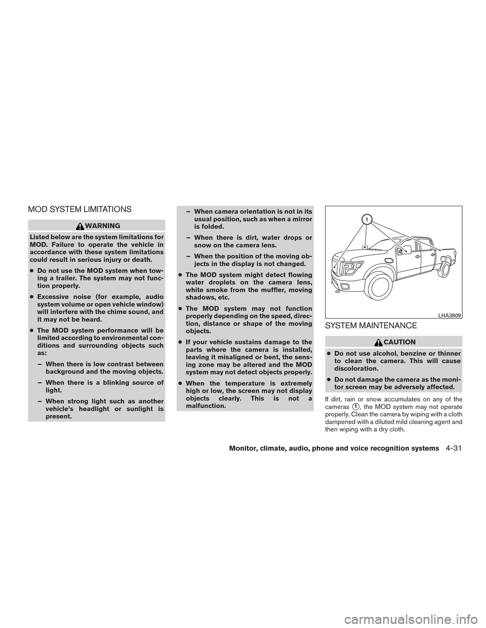
If dirt, rain or snow accumulates on any of the
cameras
�1, the MOD system may not operate
properly. Clean the camera by wiping with a cloth
dampened with a diluted mild cleaning agent and
then wiping with a dry cloth.
LHA3909
Monitor, climate, audio, phone and voice recognition systems4-31