Page 464 of 636
2. Open the engine hood.
3. Remove the fuse box cover by pushing thetab and lifting the cover up.
4. Remove the fuse with the fuse puller. The fuse puller is located in the center of the fuse
block in the passenger compartment. 5. If the fuse is open�A, replace it with a new
fuse
�B.
6. If a new fuse also opens, have the electrical system checked and repaired. It is recom-
mended that you visit a NISSAN dealer for
this service.
Fusible links
If the electrical equipment does not operate and
fuses are in good condition, check the fusible
links. If any of these fusible links are melted,
replace with only Genuine NISSAN parts.
VK56VD engine
LDI2974
Cummins 5.0L engine
LDI2882
LDI2826
Do-it-yourself8-21
Page 465 of 636
PASSENGER COMPARTMENT
WARNING
Never use a fuse of higher or lower amper-
age rating than that specified on the fuse
box cover. This could damage the electri-
cal system or electronic control units or
cause a fire.
If any electrical equipment does not operate,
check for an open fuse. 1. Be sure the ignition switch and the headlight switch are OFF.
2. Open the glove box. 3. Remove the fuse box cover.
4. Locate the fuse that needs to be replaced.
LDI0456LDI2883
8-22Do-it-yourself
Page 466 of 636
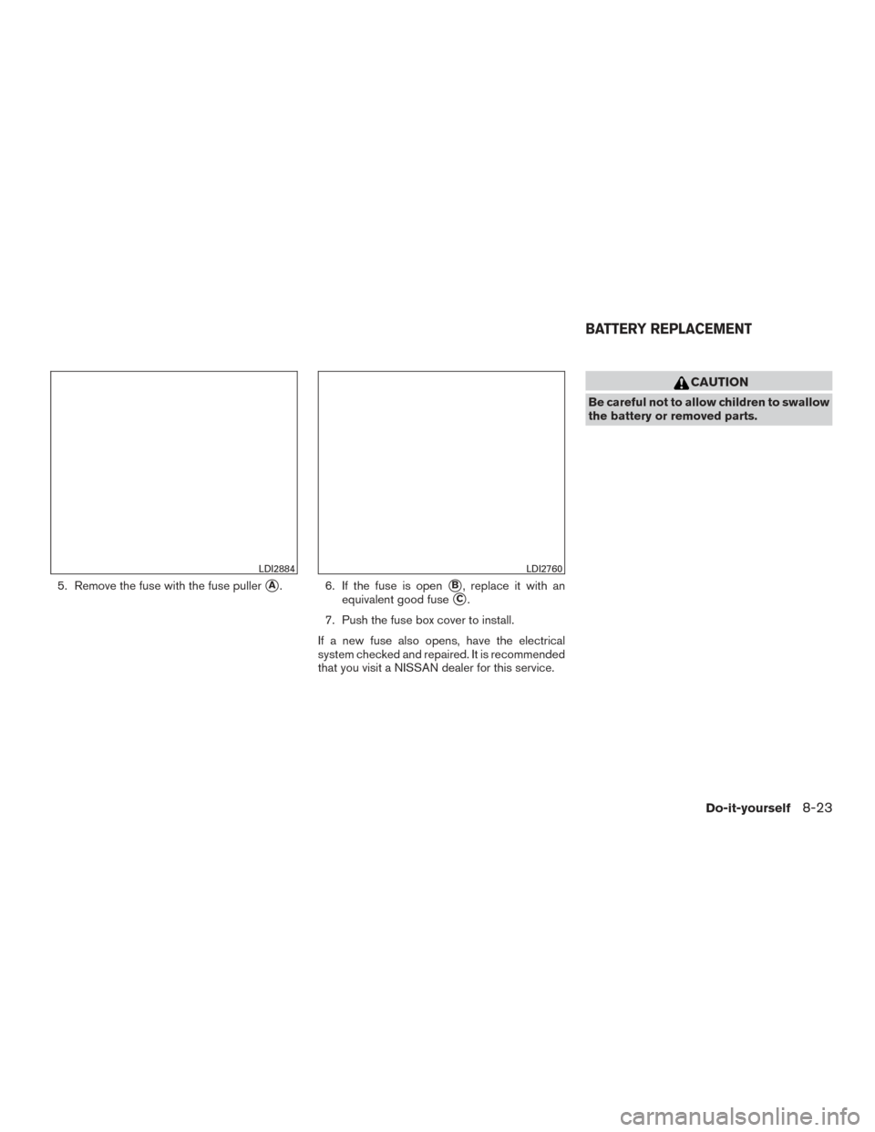
5. Remove the fuse with the fuse puller�A. 6. If the fuse is open�B, replace it with an
equivalent good fuse
�C.
7. Push the fuse box cover to install.
If a new fuse also opens, have the electrical
system checked and repaired. It is recommended
that you visit a NISSAN dealer for this service.
CAUTION
Be careful not to allow children to swallow
the battery or removed parts.
LDI2884LDI2760
BATTERY REPLACEMENT
Do-it-yourself8-23
Page 550 of 636
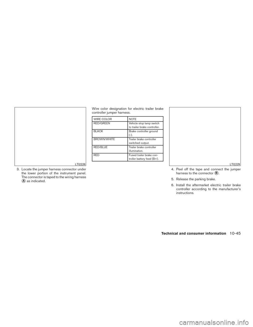
3. Locate the jumper harness connector underthe lower portion of the instrument panel.
The connector is taped to the wiring harness
�Aas indicated. Wire color designation for electric trailer brake
controller jumper harness.
WIRE COLOR
NOTE
RED/GREEN Vehicle stop lamp switch
to trailer brake controller.
BLACK Brake controller ground
(-) .
BROWN/WHITE Trailer brake controller switched output.
RED/BLUE Trailer brake controller
illumination.
RED Fused trailer brake con-
troller battery feed (B+) .
4. Peel off the tape and connect the jumper harness to the connector
�B.
5. Release the parking brake.
6. Install the aftermarket electric trailer brake controller according to the manufacturer’s
instructions.
LTI2228LTI2229
Technical and consumer information10-45
Page 564 of 636

Engine serial number............10-13
Engine specifications ............10-9
Starting the engine ..........5-14,5-16
Engine coolant temperature gauge .......2-7
Engineoilpressuregauge.........2-9,2-10
Enterbutton....................4-4
Event Data recorders .............10-56
Exhaust gas (Carbon monoxide) .........5-2
Explanation of maintenance items ........9-2
Explanation of scheduled maintenance items . .9-5
Extendedstorageswitch ............2-70
F
Flashers (See hazard warning flasher switch) . .6-2
Flat tire .......................6-3
Floor mat positioning aid .............7-5
Fluid Brake fluid ..................8-11
Capacities and recommended
fuel/lubricants ................10-2
Engine coolant .................8-4
Engine oil ...................8-6
Power steering fluid .............8-11
Windshield-washerfluid...........8-12
F.M.V.S.S. certification label ..........10-13
Foglightswitch .................2-55
Four-Wheel Drive ................5-44
Front air bag system
(See supplemental restraint system) ......1-52
Front and rear sonar system ..........5-59
Front power seat adjustment ...........1-5
Frontseats.....................1-2 Fuel
Capacities and recommended
fuel/lubricants ................10-2
Fuel economy ................5-44
Fuel gauge ...................2-8
Fuel octane rating ..............10-6
Fuel recommendation ............10-5
Loose fuel cap warning ...........2-43
Fuel Cell Vehicle (FCV) System Tirepressure.................8-31
Fuel-filler door ..................3-22
Fuelgauge.....................2-8
Fuses.......................8-20
Fusiblelinks ...................8-21
G
Garage door opener, HomeLink® Universal
Transceiver . .2-86, 2-87, 2-88, 2-89, 2-89, 2-90
Gauge Automatic transmission fluid temperature
gauge .....................2-9
Engine coolant temperature gauge .....2-7
Engine oil pressure gauge .......2-9,2-10
Fuel gauge ...................2-8
Odometer ...................2-6
Speedometer .................2-6
Tachometer ..................2-7
Trip computer ................2-11
Trip odometer .................2-6
Voltmeter...................2-10
General maintenance ...............9-2
Glovebox.....................2-74
Grocery hooks ..................2-79 H
Hands-free phone system,
Bluetooth®...............4-114, 4-127
Hazard warning flasher switch ..........6-2
Headlightaimingcontrol ............2-53
Headlightandturnsignalswitch........2-51
Headlightcontrolswitch ............2-51
Headlights....................8-25
Headlights, aiming control ............2-53
Head restraints ..................1-10
Heated rear seats ................2-58
Heated seats ...................2-57
Heated steering wheel .............2-60
Heater Heater
and air conditioner (automatic)
(if so equipped) ...............4-41
Heater and air conditioner controls .....4-42
Heater operation ...........4-34,4-43
Heater and air conditioner (automatic) .....4-41
Hill descent control switch ...........2-62
Hill descent control system ...........5-58
Hill start assist system ..............5-58
HomeLink® Universal Transceiver . . .2-86, 2-87, 2-88, 2-89, 2-89, 2-90
Hood.......................3-21
Horn .......................2-55
I
Ignition Switch Push-Button Ignition Switch ........5-10
Immobilizer system ............2-46,5-14
Important vehicle information label ......10-13
11-3
Page 600 of 636

WARNING
Always follow the instructions below. Fail-
ure to do so could result in damage to the
charging system and cause personal
injury.1. If the booster battery is in another vehicle, position the two vehicles to bring their bat-
teries near each other.
Do not allow the two vehicles to touch.
2. Apply the parking brake. Move the shift lever to P (Park) . Switch off all unnecessary elec-
trical systems (lights, heater, air conditioner,
etc.) . 3. Ensure the vent caps are level and tight.
4. Remove the fuse/fusible link box and con-
nect jumper cables in the sequence illus-
trated (
�A,�B,�C,�D).
CAUTION
●Always connect positive (�) to positive
(�) and negative (�) to body ground (for
example, strut mounting bolt, engine
lift bracket, etc.) — not to the battery.
● Make sure the jumper cables do not
touch moving parts in the engine com-
partment and that the cable clamps do
not contact any other metal. 5. Start the engine of the booster vehicle and
let it run for a few minutes.
6. Keep the engine speed of the booster ve- hicle at about 2,000 rpm, and start the en-
gine of the vehicle being jump started.
CAUTION
Do not keep the starter motor engaged for
more than 10 seconds. If the engine does
not start right away, turn the key off and
wait 3 to 4 seconds before trying again.
7. After starting the engine, carefully discon- nect the negative cable and then the positive
cable.
LCE2223
In Case of Emergency5-3
Page 603 of 636
1. Windshield-washer fluid reservoir
2. Fuse box
3. Fuse/Fusible link box
4. Engine coolant reservoir
5. Fuel filter (Stage 2)
6. Engine oil filler cap
7. Brake fluid reservoir
8. Air cleaner
9. Battery
10. Power steering fluid reservoir
11. Radiator cap
12. Engine oil dipstick
13. Drive belt location
14. Fuse/Fusible link box
15. Battery
Cummins 5.0L
LDI2870
ENGINE COMPARTMENT CHECK
LOCATIONS
6-2Do-it-yourself
Page:
< prev 1-8 9-16 17-24


6. Engine oil filler cap
7. Brake fluid reservoir
8. Air cleaner
9. Batte")