Page 72 of 478

●Immediately after inflation, several
front air bag system components will be
hot. Do not touch them; you may se-
verely burn yourself.
● No unauthorized changes should be
made to any components or wiring of
the supplemental air bag system. This is
to prevent accidental inflation of the
supplemental air bag or damage to the
supplemental air bag system.
● Do not make unauthorized changes to
your vehicle’s electrical system, sus-
pension system or front end structure.
This could affect proper operation of
the front air bag system.
● Tampering with the front air bag system
may result in serious personal injury.
Tampering includes changes to the
steering wheel and the instrument
panel assembly by placing material
over the steering wheel pad and above
the instrument panel or by installing
additional trim material around the air
bag system.
● Removing or modifying the front pas-
senger seat may affect the function of
the air bag system and result in serious
personal injury. ●
Modifying or tampering with the front
passenger seat may result in serious
personal injury. For example, do not
change the front seats by placing mate-
rial on the seat cushion or by installing
additional trim material, such as seat
covers, on the seat that are not specifi-
cally designed to assure proper air bag
operation. Additionally, do not stow any
objects under the front passenger seat
or the seat cushion and seatback. Such
objects may interfere with the proper
operation of the occupant classification
sensor (weight sensor) .
● No unauthorized changes should be
made to any components or wiring of
the seat belt system. This may affect the
front air bag system. Tampering with
the seat belt system may result in seri-
ous personal injury. ●
It is recommended that you visit a
NISSAN dealer for work on and around
the front air bag. It is also recom-
mended that you visit a NISSAN dealer
for installation of electrical equipment.
The Supplemental Restraint System
(SRS) wiring harnesses* should not be
modified or disconnected. Unauthor-
ized electrical test equipment and prob-
ing devices should not be used on the
air bag system.
● A cracked windshield should be re-
placed immediately by a qualified repair
facility. A cracked windshield could af-
fect the function of the supplemental air
bag system.
*The SRS wiring harness connectors are
yellow and orange for easy identification.
When selling your vehicle, we request that you
inform the buyer about the front air bag system
and guide the buyer to the appropriate sections
in this Owner’s Manual.
Safety—Seats, seat belts and supplemental restraint system1-55
** Click HERE to see "Owner's Manual Supplement" **
Page 81 of 478
1. Headlight/fog light (if so equipped)/turnsignal switch (P. 2-39)
2. Steering wheel switch for trip computer
(if so equipped)/vehicle information
display (if so equipped) (P. 2-8)
Audio control (P. 4-27)
3. Driver’s supplemental air bag (P. 1-48) Horn (P. 2-44)
4. Meters and gauges (P. 2-3)
5. Cruise control main/set switches
(if so equipped) (P. 5-43)
Intelligent Cruise Control switches
(if so equipped) (P. 5-45)
Bluetooth® Hands-Free Phone System
(P. 4-27)
6. Wiper and washer switch (P. 2-38)
7. Vents (P. 4-16)
8. Hazard warning flasher switch (P. 6-2)
9. Passenger air bag status light (P. 1-41)
10. Audio system (P. 4-27)
11. Passenger’s supplemental air bag
(P. 1-48)
12. Glove box (P. 2-49)
13. Shift lever (P. 5-17)
14. Climate controls (P. 4-16, 4-24)
LII2413
INSTRUMENT PANEL
2-2Instruments and controls
Page 82 of 478
15. Ignition switch (if so equipped) (P. 5-8)Push-button ignition switch
(if so equipped) (P. 5-10)
16. Telescopic steering (P. 3-29)
17. Hood release (P. 3-24)
18. Fuel filler door release (P. 3-26)
19. ECO mode switch (P. 5-22) Vehicle Dynamic Control (VDC) OFF
switch (P. 2-45)
SPORT mode switch (P. 5-22)
20. Instrument brightness control (P. 2-39) Power mirror switch (P. 3-32)
Trunk release (P. 3-25)
Refer to the page number indicated in pa-
rentheses for operating details.
1. Tachometer
2. Coolant temperature gauge
3. Warning and indicator lights
4. Fuel gauge
5. Speedometer 6. Odometer
Trip computer
Twin trip odometer
Fuel Economy
ECO mode indicator
Outside temperature display
Type A (if so equipped)
LIC3415
METERS AND GAUGES
Instruments and controls2-3
Page 84 of 478
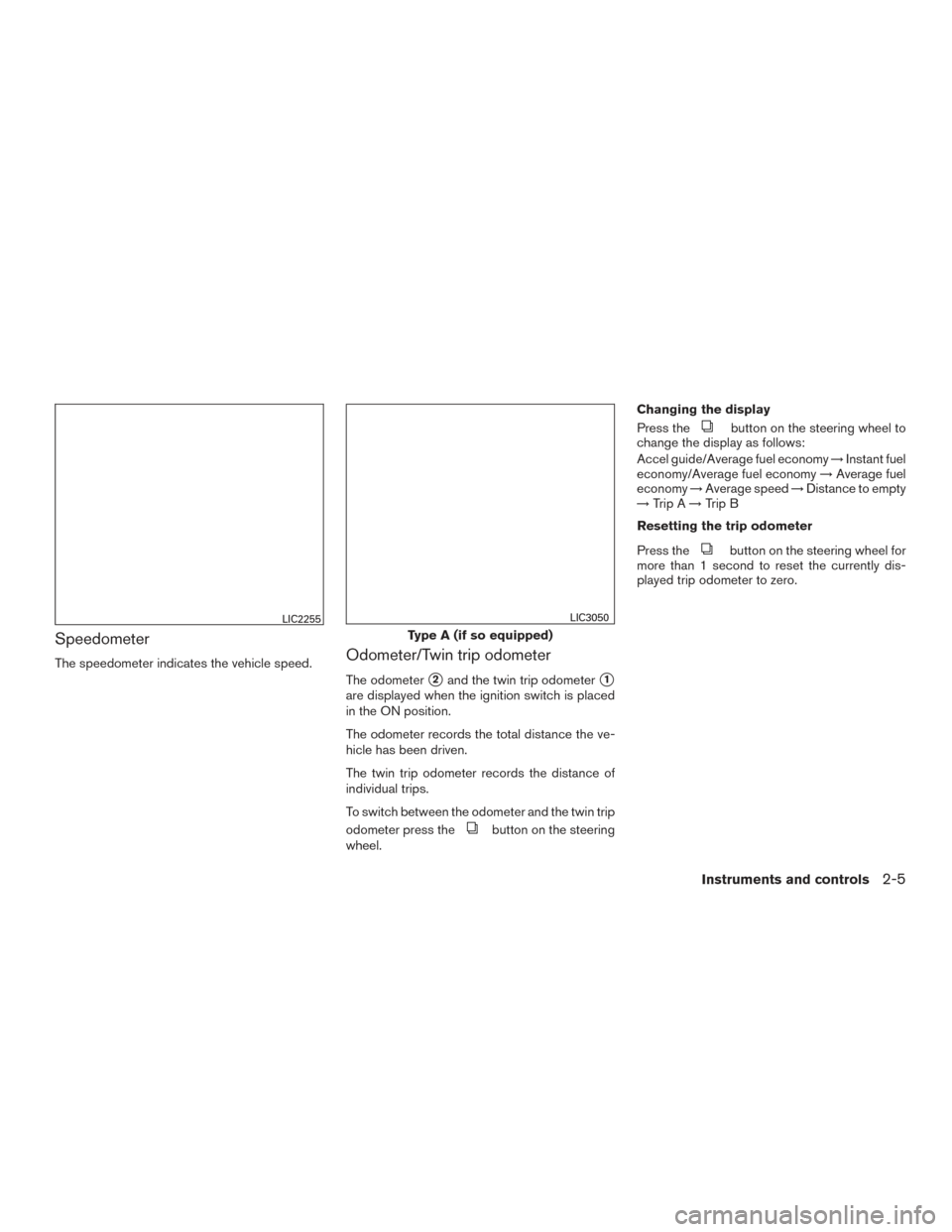
Speedometer
The speedometer indicates the vehicle speed.Odometer/Twin trip odometer
The odometer�2and the twin trip odometer�1
are displayed when the ignition switch is placed
in the ON position.
The odometer records the total distance the ve-
hicle has been driven.
The twin trip odometer records the distance of
individual trips.
To switch between the odometer and the twin trip
odometer press the
button on the steering
wheel. Changing the display
Press the
button on the steering wheel to
change the display as follows:
Accel guide/Average fuel economy →Instant fuel
economy/Average fuel economy →Average fuel
economy →Average speed →Distance to empty
→ Trip A →Trip B
Resetting the trip odometer
Press the
button on the steering wheel for
more than 1 second to reset the currently dis-
played trip odometer to zero.
LIC2255
Type A (if so equipped)
LIC3050
Instruments and controls2-5
Page 85 of 478

Loose fuel cap warning message
Push the reset button�Afor more than 1 second
to reset the LOOSE FUEL CAP warning mes-
sage
�Bafter the fuel cap has been tightened.
For additional information, refer to “Fuel-filler
cap” in the “Pre-driving checks and adjustments”
section of this manual.
Check tire pressure warning message
The CHECK TIRE PRES warning message is
displayed when the low tire pressure warning
light is illuminated and low tire pressure is de-
tected. Check and adjust the tire pressure to the
recommended COLD tire pressure shown on the
Tire and Loading Information label. The CHECK
TIRE PRES warning message can be turned off
using the reset button
�Aon the steering wheel.
The low tire pressure warning light will not be
turned off. The low tire pressure warning light remains illu-
minated until the tires are inflated to the recom-
mended COLD tire pressure. The CHECK TIRE
PRES warning message is displayed each time
the ignition switch is placed in the ON position as
long as the low tire pressure warning light re-
mains illuminated. For additional information, re-
fer to “Low tire pressure warning light” in the
“Instruments and controls” section, “Tire Pres-
sure Monitoring System (TPMS)” in the “Starting
and driving” section and “Wheels and tires” in the
“Maintenance and do-it-yourself” section of this
manual.
Type A (if so equipped)
LPD2124
Type A (if so equipped)
LIC2678
2-6Instruments and controls
Page 87 of 478

FUEL GAUGE
NOTE:
The ignition switch must be placed in the
ON position for the gauge to give a reading.
The gauge indicates theapproximatefuel level
in the tank.
The gauge may move slightly during braking,
turning, acceleration, or going up or down hills.
The low fuel warning light comes on when the
amount of fuel in the tank is getting low. Refill the fuel tank before the gauge regis-
ters 0 (Empty) .The arrow on the fuel pump symbol indi-
cates the fuel-filler location.
CAUTION
● If the vehicle runs out of fuel, theMalfunction Indicator Light (MIL) may
come on. Refuel as soon as possible.
After a few driving trips. the
light
should turn off. If the light remains on
after a few driving trips, have the vehicle
inspected. It is recommended you visit a
NISSAN dealer for this service.
● For additional information, refer to
“Malfunction Indicator Light (MIL)” in
this section.
TRIP COMPUTER (if so equipped)
When the ignition switch is placed in the ON
position, the modes of the trip computer can be
selected by pressing the
button on the
steering wheel. The following modes can be se-
lected:
● Trip A
● Trip B
● ECO Pedal Indicator
● Instant fuel economy
● Average fuel economy
● Average speed
Type A (if so equipped)
LIC2445
Type B (if so equipped)
LIC2222
2-8Instruments and controls
Page 89 of 478

NOTE:
The ECO Pedal Indicator’s bar is not dis-
played when the cruise control is in opera-
tion.
AVE & INST fuel economy
When Average & Instant fuel economy informa-
tion is displayed, there will be different sections
to read:
�AInstant fuel economy (BAR graph)
�BAverage fuel economy (BAR & DIGIT)
The bar graph is not displayed when vehicle
speed is 0 mph (US market) or 0 km/h (Canada
market) .
Instant fuel economy
The instant fuel economy mode shows the instant
fuel economy. The display updates instantly when
driving.
Average fuel economy
The average fuel economy mode shows the av-
erage fuel economy since the last reset. Reset-
ting is done by pressing the
button on the
steering wheel for more than approximately
1 second. The display is updated every 30 sec-
onds. At about the first 1/3 mile (500 m) after a
reset, the display shows (----) .
Average speed
The average speed mode shows the average
vehicle speed since last reset. Resetting is done
by pressing the
button on the steering
wheel for more than approximately 1 second. The
display is updated every 30 seconds. The first
30 seconds after a reset, the display shows
(----) .
LIC3147
2-10Instruments and controls
Page 90 of 478
 mode provides you
with an estimation of the distance that can be
driven before refueling. The dte is constantly be-
ing calculated, based on the amount of")
Distance to empty
The distance to empty (dte) mode provides you
with an estimation of the distance that can be
driven before refueling. The dte is constantly be-
ing calculated, based on the amount of fuel in the
fuel tank and the actual fuel economy which will
depend on driving conditions. Dashes (—) indi-
cate that fuel remaining volume cannot be read by
the fuel pump and should be refilled as soon as
possible.
The display is updated every 30 seconds.NOTE:
When driving uphill or rounding curves, the
fuel in the tank shifts, which may momen-
tarily change the display.
Trip computer reset
To reset Trip A, Trip B, AVG/mpg, or AVG/mph,
go to the desired mode on the trip computer and
hold the
button on the steering wheel for
more than 3 seconds.
OUTSIDE TEMPERATURE DISPLAY
(if so equipped)
The outside temperature function provides a dis-
play of the outside temperature when the ignition
switch is placed in the ON position.
The display of positive temperatures is unsigned
(blank) , negative temperatures are prefixed with a
minus sign.
The outside temperature will always be visible on
the left side of the display.
LIC3148LIC3149
Instruments and controls2-11
/turnsignal switch (P. 2-39)
2. Steering wheel switch for trip computer
(if so equipped)/vehicle information
display (if so equipped) (P. 2-8)
Audio control (P.")
 (P. 5-8)Push-button ignition switch
(if so equipped) (P. 5-10)
16. Telescopic steering (P. 3-29)
17. Hood release (P. 3-24)
18. Fuel filler door release (P. 3-26)")