Page 184 of 478
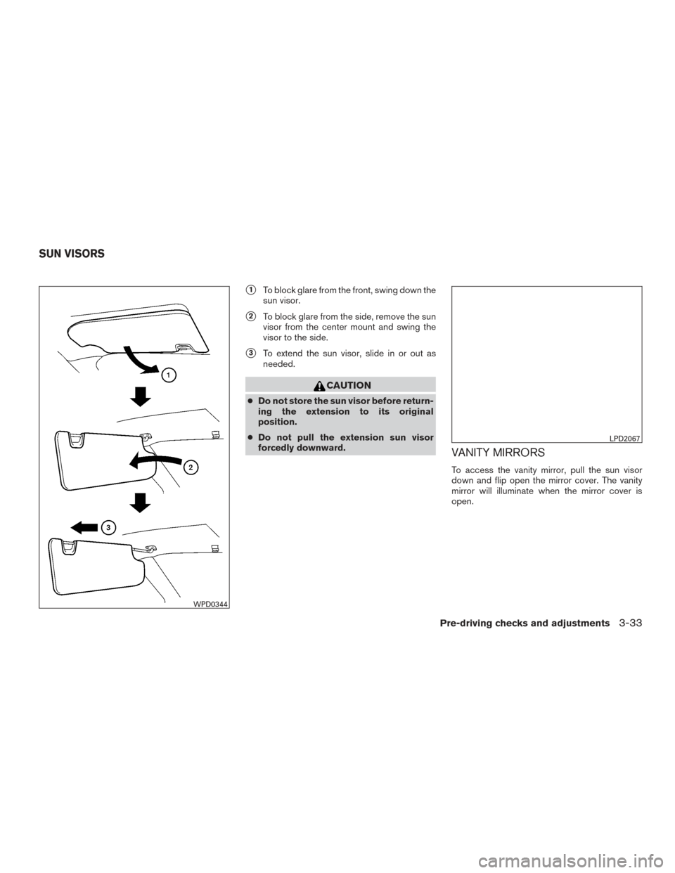
�1To block glare from the front, swing down the
sun visor.
�2To block glare from the side, remove the sun
visor from the center mount and swing the
visor to the side.
�3To extend the sun visor, slide in or out as
needed.
CAUTION
● Do not store the sun visor before return-
ing the extension to its original
position.
● Do not pull the extension sun visor
forcedly downward.
VANITY MIRRORS
To access the vanity mirror, pull the sun visor
down and flip open the mirror cover. The vanity
mirror will illuminate when the mirror cover is
open.
WPD0344
LPD2067
SUN VISORS
Pre-driving checks and adjustments3-33
Page 185 of 478
CARD HOLDER (driver’s side only)
To access the card holder, slide card in the card
holder. Do not view information while operating
the vehicle.
MANUAL ANTI-GLARE REARVIEW
MIRROR (if so equipped)
Use the night position�1to reduce glare from
the headlights of vehicles behind you at night.
Use the day position
�2when driving in daylight
hours.
WARNING
Use the night position only when neces-
sary, because it reduces rear view clarity.
AUTOMATIC ANTI-GLARE
REARVIEW MIRROR (if so equipped)
The inside mirror is designed so that it automati-
cally dims during night time conditions and ac-
cording to the intensity of the headlights of the
vehicle following you. The automatic anti-glare
feature is activated when the ignition switch is in
the ON position.
LPD2120WPD0126
Type A (if so equipped)
WPD0446
MIRRORS
3-34Pre-driving checks and adjustments
Page 186 of 478

NOTE:
Do not hang any objects over the sensors
�1or apply glass cleaner to the sensors.
Doing so will reduce the sensitivity of the
sensors, resulting in improper operation.
The indicator light
�2will illuminate when the
automatic anti-glare feature is operating. Type A (if so equipped):
● To turn off the anti-glare feature, press
the
button. The indicator light will turn
off.
● To turn on the anti-glare feature, press
the
button again. The indicator light
will turn on.
Type B (if so equipped):
● To turn off the automatic anti-glare feature,
press the O button. The indicator light
will turn off.
● To turn on the automatic anti-glare feature
again, press the | button again. The in-
dicator light will turn on.
OUTSIDE MIRRORS
The outside mirror remote control will operate
only when the ignition switch is in the ACC or ON
position.
Move the small switch
�1to select the left or right
mirror. Adjust each mirror to the desired position
using the large switch
�2.
Type B (if so equipped)
LPD0469LPD2083
Pre-driving checks and adjustments3-35
Page 187 of 478
WARNING
●Objects viewed in the outside mirror on
the passenger side are closer than they
appear. Be careful when moving to the
right. Using only this mirror could cause
an accident. Use the inside mirror or
glance over your shoulder to properly
judge distances to other objects.
● Do not adjust the mirrors while driving.
You could lose control of your vehicle
and cause an accident.
Manual folding outside mirrors
Pull the outside mirror toward the door to fold it.
Heated mirrors (if so equipped)
Some outside mirrors can be heated to defrost,
defog, or de-ice for improved visibility. For addi-
tional information, refer to “Rear window and
outside mirror (if so equipped) defroster switch”
in the “Instruments and controls” section of this
manual.
LPD2084
3-36Pre-driving checks and adjustments
Page 197 of 478
WARNING
●Failure to follow the warnings and in-
structions for proper use of the Rear-
View Monitor system could result in se-
rious injury or death. ●
RearView Monitor is a convenience fea-
ture and is not a substitute for proper
backing. Always turn and look out the
windows and check mirrors to be sure
that it is safe to move before operating
the vehicle. Always back up slowly. ●
The system is designed as an aid to the
driver in showing large stationary ob-
jects directly behind the vehicle, to help
avoid damaging the vehicle.
LHA3749
REARVIEW MONITOR (if so
equipped)
4-10Monitor, climate, audio, phone and voice recognition systems
Page 201 of 478
 .
2. Press the ENTER/SETTING button.
3. Turn the TUNE/SCROLL knob to highlight the “Brightness” or �")
ADJUSTING THE SCREEN
1. Firmly apply your foot to the brake and putthe vehicle into R (Reverse) .
2. Press the ENTER/SETTING button.
3. Turn the TUNE/SCROLL knob to highlight the “Brightness” or “Contrast” option.
4. Press the ENTER/SETTING button.
5. Adjust the level using the TUNE/SCROLL knob and then press the ENTER/SETTING
button to apply the adjustment. NOTE:
Do not adjust any of the display settings of
the RearView Monitor while the vehicle is
moving. Make sure the parking brake is
firmly applied.
REARVIEW MONITOR SYSTEM
LIMITATIONS
WARNING
Listed below are the system limitations for
RearView Monitor. Failure to operate the
vehicle in accordance with these system
limitations could result in serious injury or
death.
●
The system cannot completely elimi-
nate blind spots and may not show ev-
ery object.
● Underneath the bumper and the corner
areas of the bumper cannot be viewed
on the RearView Monitor because of its
monitoring range limitation. The system
will not show small objects below the
bumper, and may not show objects
close to the bumper or on the ground.
● Objects viewed in the RearView Moni-
tor differ from actual distance because
a wide-angle lens is used. ●
Objects in the RearView Monitor will
appear visually opposite compared to
when viewed in the rearview and out-
side mirrors.
● Use the displayed lines as a reference.
The lines are highly affected by the
number of occupants, fuel level, vehicle
position, road conditions and road
grade.
● Make sure that the liftgate is securely
closed when backing up.
● Do not put anything on the rearview
camera. The rearview camera is in-
stalled above the license plate.
● When washing the vehicle with high
pressure water, be sure not to spray it
around the camera. Otherwise, water
may enter the camera unit causing wa-
ter condensation on the lens, a mal-
function, fire or an electric shock.
● Do not strike the camera. It is a preci-
sion instrument. Otherwise, it may mal-
function or cause damage resulting in a
fire or an electric shock.
LHA3639
4-14Monitor, climate, audio, phone and voice recognition systems
Page 204 of 478

WARNING
●Failure to follow the warnings and in-
structions for the proper use of the
Around View® Monitor system could
result in serious injury or death.
● The Around View® Monitor is a conve-
nience feature and is not a substitute
for proper vehicle operation because it
has areas where objects cannot be
viewed. The four corners of the vehicle
in particular, are areas where objects do
not always appear in the bird’s-eye,
front, or rear views. Always check your
surroundings to be sure that it is safe to
move before operating the vehicle. Al-
ways operate the vehicle slowly.
● The driver is always responsible for
safety during parking and other
maneuvers.
CAUTION
Do not scratch the camera lens when
cleaning dirt or snow from the front of the
camera. The Around View® Monitor system is designed
as an aid to the driver in situations such as slot
parking or parallel parking.
The monitor displays various views of the position
of the vehicle in a split screen format. Not all
views are available at all times.
Available views:
● Front View
An approximately 150–degree view of the
front of the vehicle.
● Rear View
An approximately 150–degree view of the
rear of the vehicle.
● Bird’s-Eye View
The surrounding views of the vehicle from
above.
● Front-Side View
The view around and ahead of the front
passenger’s side wheel. To display the multiple views, the Around View®
Monitor system uses cameras located in the front
grille, on the vehicle’s outside mirrors and one
just above the vehicle’s license plate
�1.
AROUND VIEW® MONITOR
SYSTEM OPERATION
With the ignition switch in the ON position, move
the shift lever to the R (Reverse) position or press
the CAMERA button to operate the Around
View® Monitor.
LHA3700
Monitor, climate, audio, phone and voice recognition systems4-17
Page 205 of 478

The screen displayed on the Around View®
Monitor will automatically return to the previous
screen 3 minutes after the CAMERA button has
been pressed with the shift lever in a position
other than the R (Reverse) position.
Available views
WARNING
●The distance guide lines and the vehicle
width lines should be used as a refer-
ence only when the vehicle is on a
paved, level surface. The apparent dis-
tance viewed on the monitor may be
different than the actual distance be-
tween the vehicle and displayed
objects.
● Use the displayed lines and the bird’s-
eye view as a reference. The lines and
the bird’s-eye view are greatly affected
by the number of occupants, cargo, fuel
level, vehicle position, road condition
and road grade.
● If the tires are replaced with different
sized tires, the predicted course lines
and the bird’s-eye view may be dis-
played incorrectly. ●
When driving the vehicle up a hill, ob-
jects viewed in the monitor are further
than they appear. When driving the ve-
hicle down a hill, objects viewed in the
monitor are closer than they appear.
● Objects in the rear view will appear vi-
sually opposite compared to when
viewed in the monitor and outside
mirrors.
● Use the mirrors or actually look to prop-
erly judge distances to other objects.
● On a snow-covered or slippery road,
there may be a difference between the
predicted course lines and the actual
course line.
● The vehicle width and predicted course
lines are wider than the actual width
and course.
● The displayed lines will appear slightly
off to the right, because the rearview
camera is not installed in the rear center
of the vehicle. Front and rear view
Guiding lines that indicate the approximate ve-
hicle width and distance to objects with refer-
ence to the vehicle body line
�Aare displayed on
the monitor.
Distance guide lines
Indicate distances from the vehicle body:
● Red line
�1: approximately 1.5 ft (0.5 m)
● Yellow line
�2: approximately 3 ft (1 m)
● Green line
�3: approximately 7 ft (2 m)
● Green line
�4: approximately 10 ft (3 m)
Front view
SAA1840
4-18Monitor, climate, audio, phone and voice recognition systems

To access the card holder, slide card in the card
holder. Do not view information while operating
the vehicle.
MANUAL ANTI-GLARE REARVIEW
MIRROR (if so equipped)
Use")

