2016 NISSAN NOTE wipers
[x] Cancel search: wipersPage 2320 of 3641

GENERAL MAINTENANCEMA-5
< PERIODIC MAINTENANCE >
C
DE
F
G H
I
J
K L
M B
MA
N
O A
PERIODIC MAINTENANCE
GENERAL MAINTENANCE
Explanation of Gene
ral MaintenanceINFOID:0000000012432243
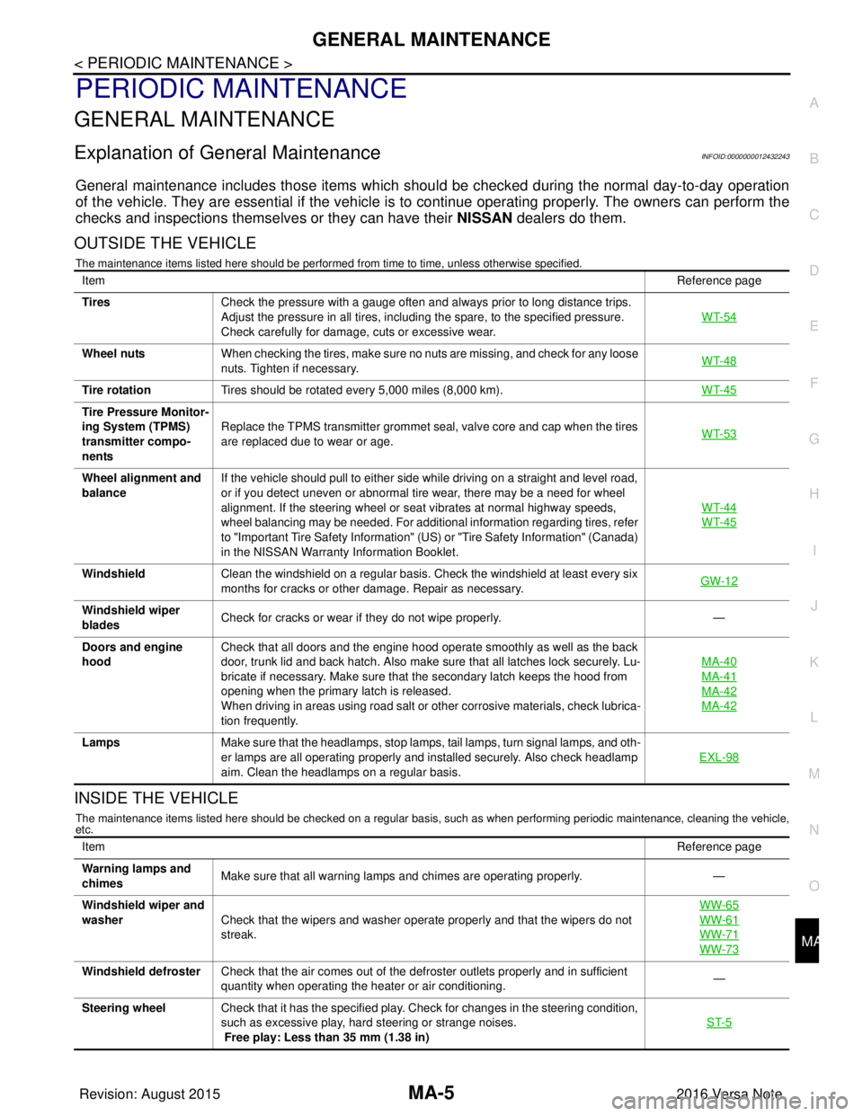
General maintenance includes those items which shoul d be checked during the normal day-to-day operation
of the vehicle. They are essential if the vehicle is to continue operati ng properly. The owners can perform the
checks and inspections themselves or they can have their NISSAN dealers do them.
OUTSIDE THE VEHICLE
The maintenance items listed here should be performed from time to time, unless otherwise specified.
INSIDE THE VEHICLE
The maintenance items listed here should be checked on a regular basis, such as when performing periodic maintenance, cleaning the vehicle,
etc.
Item Reference page
Tires Check the pressure with a gauge often and always prior to long distance trips.
Adjust the pressure in all tires, including the spare, to the specified pressure.
Check carefully for damage, cuts or excessive wear. WT-54
Wheel nuts
When checking the tires, make sure no nuts are missing, and check for any loose
nuts. Tighten if necessary. WT-48
Tire rotation
Tires should be rotated every 5,000 miles (8,000 km). WT-45
Tire Pressure Monitor-
ing System (TPMS)
transmitter compo-
nentsReplace the TPMS transmitter grommet seal, valve core and cap when the tires
are replaced due to wear or age.
WT-53
Wheel alignment and
balanceIf the vehicle should pull to either side while driving on a straight and level road,
or if you detect uneven or abnormal tire wear, there may be a need for wheel
alignment. If the steering wheel or seat vibrates at normal highway speeds,
wheel balancing may be needed. For additional information regarding tires, refer
to "Important Tire Safety Information" (US) or "Tire Safety Information" (Canada)
in the NISSAN Warranty
Information Booklet. WT-44
WT-45
Windshield
Clean the windshield on a regular basis. Check the windshield at least every six
months for cracks or other damage. Repair as necessary. GW-12
Windshield wiper
bladesCheck for cracks or wear if they do not wipe properly.
—
Doors and engine
hood Check that all doors and the engine hood operate smoothly as well as the back
door, trunk lid and back hatch. Also make sure that all latches lock securely. Lu-
bricate if necessary. Make sure that the secondary latch keeps the hood from
opening when the primary latch is released.
When driving in areas using road salt or other corrosive materials, check lubrica-
tion frequently. MA-40
MA-41
MA-42
MA-42
Lamps
Make sure that the headlamps, stop lamps, tail lamps, turn signal lamps, and oth-
er lamps are all operating properly and installed securely. Also check headlamp
aim. Clean the headlamps on a regular basis. EXL-98
Item
Reference page
Warning lamps and
chimes Make sure that all warning lamps and chimes are operating properly.
—
Windshield wiper and
washer Check that the wipers and washer operate properly and that the wipers do not
streak. WW-65
WW-61
WW-71
WW-73
Windshield defroster
Check that the air comes out of the defroster outlets properly and in sufficient
quantity when operating the heater or air conditioning. —
Steering wheel Check that it has the specified play. Check for changes in the steering condition,
such as excessive play, hard steering or strange noises.
Free play: Less than 35 mm (1.38 in) ST-5
Revision: August 2015
2016 Versa Note
cardiagn.com
Page 3572 of 3641

COMPONENT PARTSWW-7
< SYSTEM DESCRIPTION >
C
DE
F
G H
I
J
K
M A
B
WW
N
O P
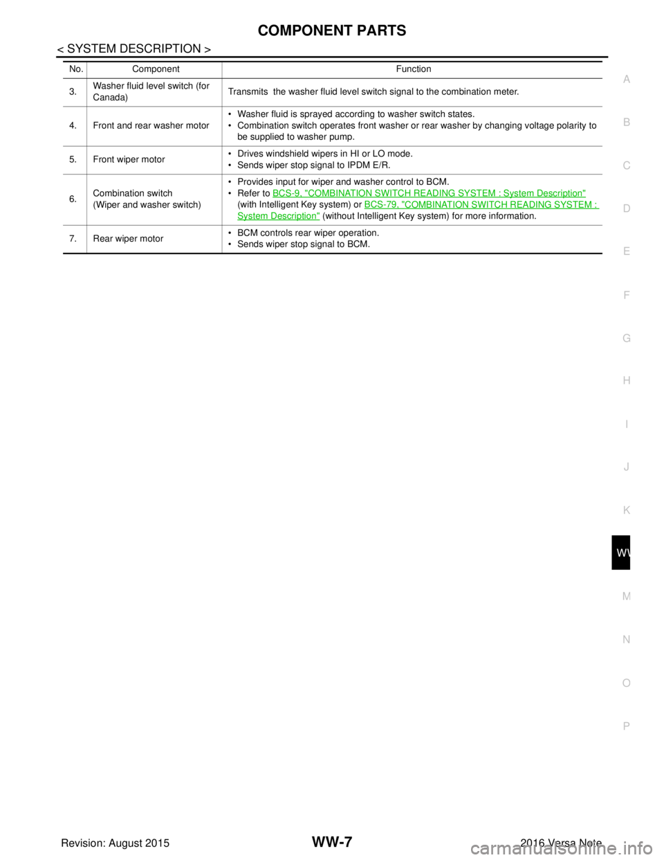
3. Washer fluid level switch (for
Canada) Transmits the washer fluid level switch signal to the combination meter.
4. Front and rear washer motor • Washer fluid is sprayed according to washer switch states.
• Combination switch operates front washer or rear washer by changing voltage polarity to
be supplied to washer pump.
5. Front wiper motor • Drives windshield wipers in HI or LO mode.
• Sends wiper stop signal to IPDM E/R.
6. Combination switch
(Wiper and washer switch) • Provides input for wiper and washer control to BCM.
• Refer to
BCS-9, "
COMBINATION SWITCH READING SYSTEM : System Description"
(with Intelligent Key system) or BCS-79, "
COMBINATION SWITCH READING SYSTEM :
System Description" (without Intelligent Key system) for more information.
7. Rear wiper motor • BCM controls rear wiper operation.
• Sends wiper stop signal to BCM.
No.
Component Function
Revision: August 2015 2016 Versa Note
cardiagn.com
Page 3616 of 3641

WIPER AND WASHER SYSTEM SYMPTOMSWW-51
< SYMPTOM DIAGNOSIS >
C
DE
F
G H
I
J
K
M A
B
WW
N
O P
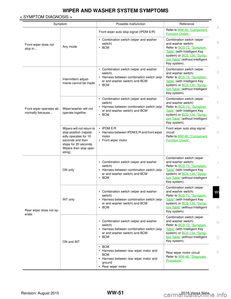
Front wiper does not
stop in... Any modeFront wiper auto stop signal (IPDM E/R)
Refer to
WW-40, "
Component
Function Check".
• Combination switch (wiper and washer switch)
•BCM Combination switch (wiper
and washer switch)
Refer to
BCS-72, "
Symptom
Ta b l e" (with Intelligent Key
system) or BCS-134, "
Symp-
tom Table" (without Intelligent
Key system).
Front wiper operates ab-
normally because... Intermittent adjust-
ments cannot be made.
• Combination switch (wiper and washer
switch)
• Harness between combination switch (wip- er and washer switch) and BCM
•BCM Combination switch (wiper
and washer switch)
Refer to
BCS-72, "
Symptom
Ta b l e" (with Intelligent Key
system) or BCS-134, "
Symp-
tom Table" (without Intelligent
Key system).
Wiper/washer will not
operate together. • Combination switch (wiper and washer
switch)
• Harness between combination switch (wip- er and washer switch) and BCM
•BCM Combination switch (wiper
and washer switch)
Refer to
BCS-72, "
Symptom
Ta b l e" (with Intelligent Key
system) or BCS-134, "
Symp-
tom Table" (without Intelligent
Key system).
Wipers will not return to
stop position (repeat-
edly operates for 10
seconds and then
stops for 20 seconds.
Wipers then stop oper-
ating). • IPDM E/R
• Harness between IPDM E/R and front wiper
motor
• Front wiper motor Front wiper auto stop signal
circuit
Refer to
WW-40, "
Component
Function Check".
Rear wiper does not op-
erate. ON only
• Combination switch (wiper and washer
switch)
• Harness between combination switch (wip-
er and washer switch) and BCM
•BCM Combination switch (wiper
and washer switch)
Refer to
BCS-72, "
Symptom
Ta b l e" (with Intelligent Key
system) or BCS-134, "
Symp-
tom Table" (without Intelligent
Key system).
INT only • Combination switch (wiper and washer
switch)
• Harness between combination switch (wip- er and washer switch) and BCM
•BCM Combination switch (wiper
and washer switch)
Refer to
BCS-72, "
Symptom
Ta b l e" (with Intelligent Key
system) or BCS-134, "
Symp-
tom Table" (without Intelligent
Key system).
ON and INT • Combination switch (wiper and washer
switch)
• Harness between combination switch (wip- er and washer switch) and BCM
•BCM Combination switch (wiper
and washer switch)
Refer to
BCS-72, "
Symptom
Ta b l e" (with Intelligent Key
system) or BCS-134, "
Symp-
tom Table" (without Intelligent
Key system).
•BCM
• Harness between rear wiper motor and BCM
• Harness between rear wiper motor and ground
• Rear wiper motor Rear wiper motor circuit
Refer to
WW-46, "
Diagnosis
Procedure".
Symptom
Possible malfunction Reference
Revision: August 2015 2016 Versa Note
cardiagn.com
Page 3618 of 3641

FRONT WIPER DOES NOT OPERATEWW-53
< SYMPTOM DIAGNOSIS >
C
DE
F
G H
I
J
K
M A
B
WW
N
O P
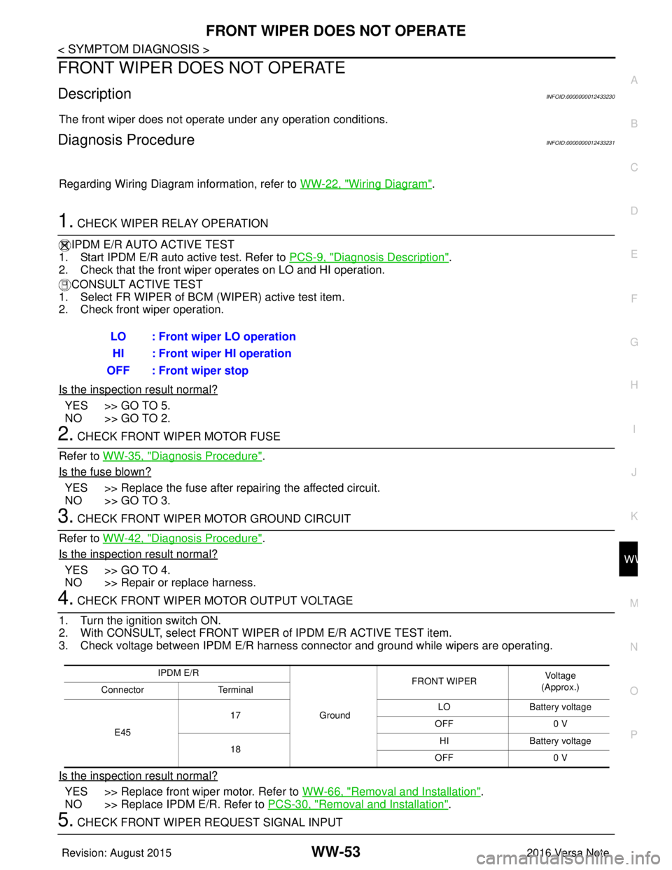
FRONT WIPER DO ES NOT OPERATE
DescriptionINFOID:0000000012433230
The front wiper does not operate under any operation conditions.
Diagnosis ProcedureINFOID:0000000012433231
Regarding Wiring Diagram information, refer to WW-22, "Wiring Diagram".
1. CHECK WIPER RELAY OPERATION
IPDM E/R AUTO ACTIVE TEST
1. Start IPDM E/R auto active test. Refer to PCS-9, "
Diagnosis Description".
2. Check that the front wiper operates on LO and HI operation.
CONSULT ACTIVE TEST
1. Select FR WIPER of BCM (WIPER) active test item.
2. Check front wiper operation.
Is the inspection result normal?
YES >> GO TO 5.
NO >> GO TO 2.
2. CHECK FRONT WIPER MOTOR FUSE
Refer to WW-35, "
Diagnosis Procedure".
Is the fuse blown?
YES >> Replace the fuse after repairing the affected circuit.
NO >> GO TO 3.
3. CHECK FRONT WIPER MOTOR GROUND CIRCUIT
Refer to WW-42, "
Diagnosis Procedure".
Is the inspection result normal?
YES >> GO TO 4.
NO >> Repair or replace harness.
4. CHECK FRONT WIPER MOTOR OUTPUT VOLTAGE
1. Turn the ignition switch ON.
2. With CONSULT, select FRONT WIPER of IPDM E/R ACTIVE TEST item.
3. Check voltage between IPDM E/R harness connector and ground while wipers are operating.
Is the inspection result normal?
YES >> Replace front wiper motor. Refer to WW-66, "Removal and Installation".
NO >> Replace IPDM E/R. Refer to PCS-30, "
Removal and Installation".
5. CHECK FRONT WIPER REQUEST SIGNAL INPUTLO : Front wiper LO operation
HI : Front wiper HI operation
OFF : Front wiper stop
IPDM E/R
GroundFRONT WIPER
Vo l ta g e
(Approx.)
Connector Terminal
E45 17
LO
Battery voltage
OFF 0 V
18 HI
Battery voltage
OFF 0 V
Revision: August 2015 2016 Versa Note
cardiagn.com