2016 NISSAN MURANO key
[x] Cancel search: keyPage 177 of 465
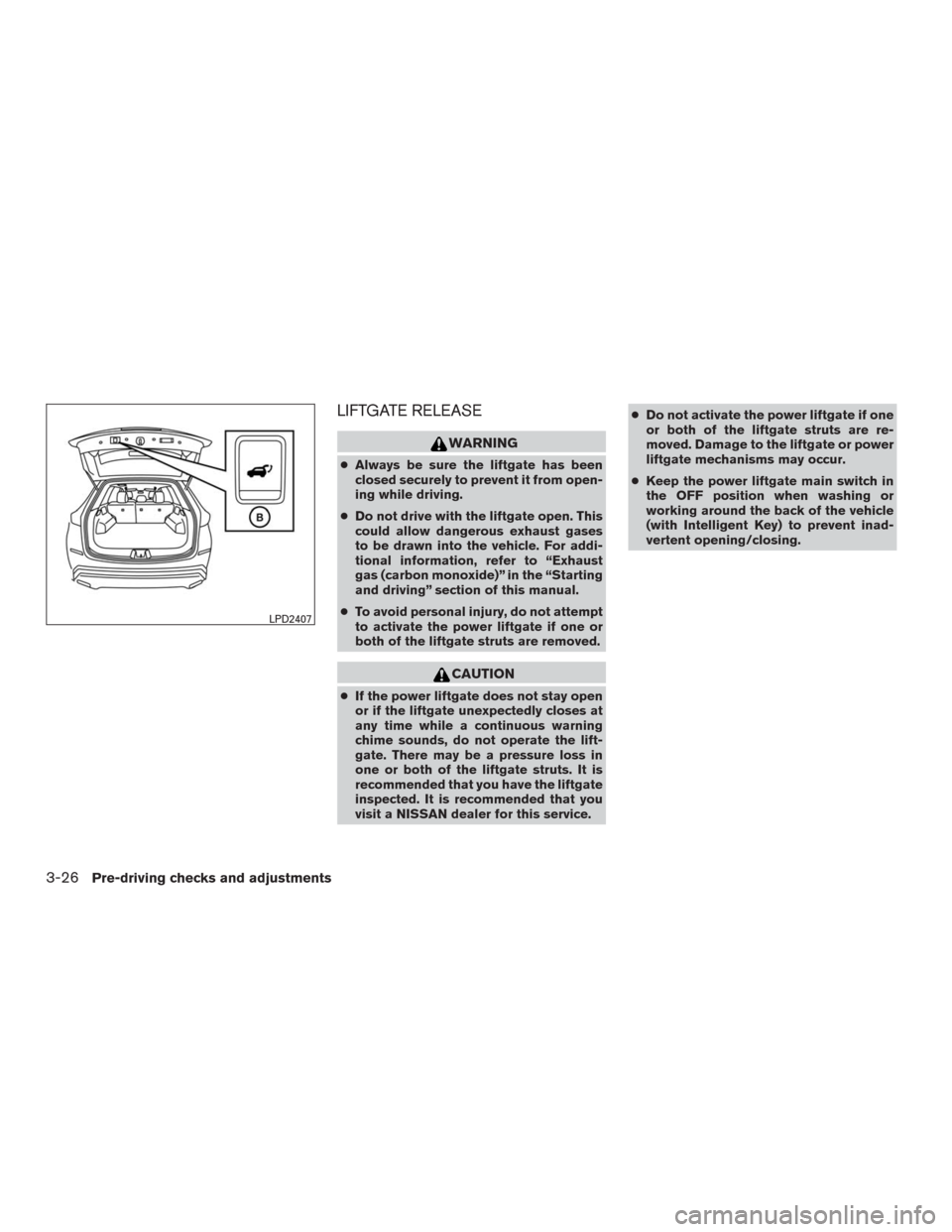
LIFTGATE RELEASE
WARNING
●Always be sure the liftgate has been
closed securely to prevent it from open-
ing while driving.
●Do not drive with the liftgate open. This
could allow dangerous exhaust gases
to be drawn into the vehicle. For addi-
tional information, refer to “Exhaust
gas (carbon monoxide)” in the “Starting
and driving” section of this manual.
●To avoid personal injury, do not attempt
to activate the power liftgate if one or
both of the liftgate struts are removed.
CAUTION
●If the power liftgate does not stay open
or if the liftgate unexpectedly closes at
any time while a continuous warning
chime sounds, do not operate the lift-
gate. There may be a pressure loss in
one or both of the liftgate struts. It is
recommended that you have the liftgate
inspected. It is recommended that you
visit a NISSAN dealer for this service.●Do not activate the power liftgate if one
or both of the liftgate struts are re-
moved. Damage to the liftgate or power
liftgate mechanisms may occur.
●Keep the power liftgate main switch in
the OFF position when washing or
working around the back of the vehicle
(with Intelligent Key) to prevent inad-
vertent opening/closing.
LPD2407
3-26Pre-driving checks and adjustments
Page 178 of 465
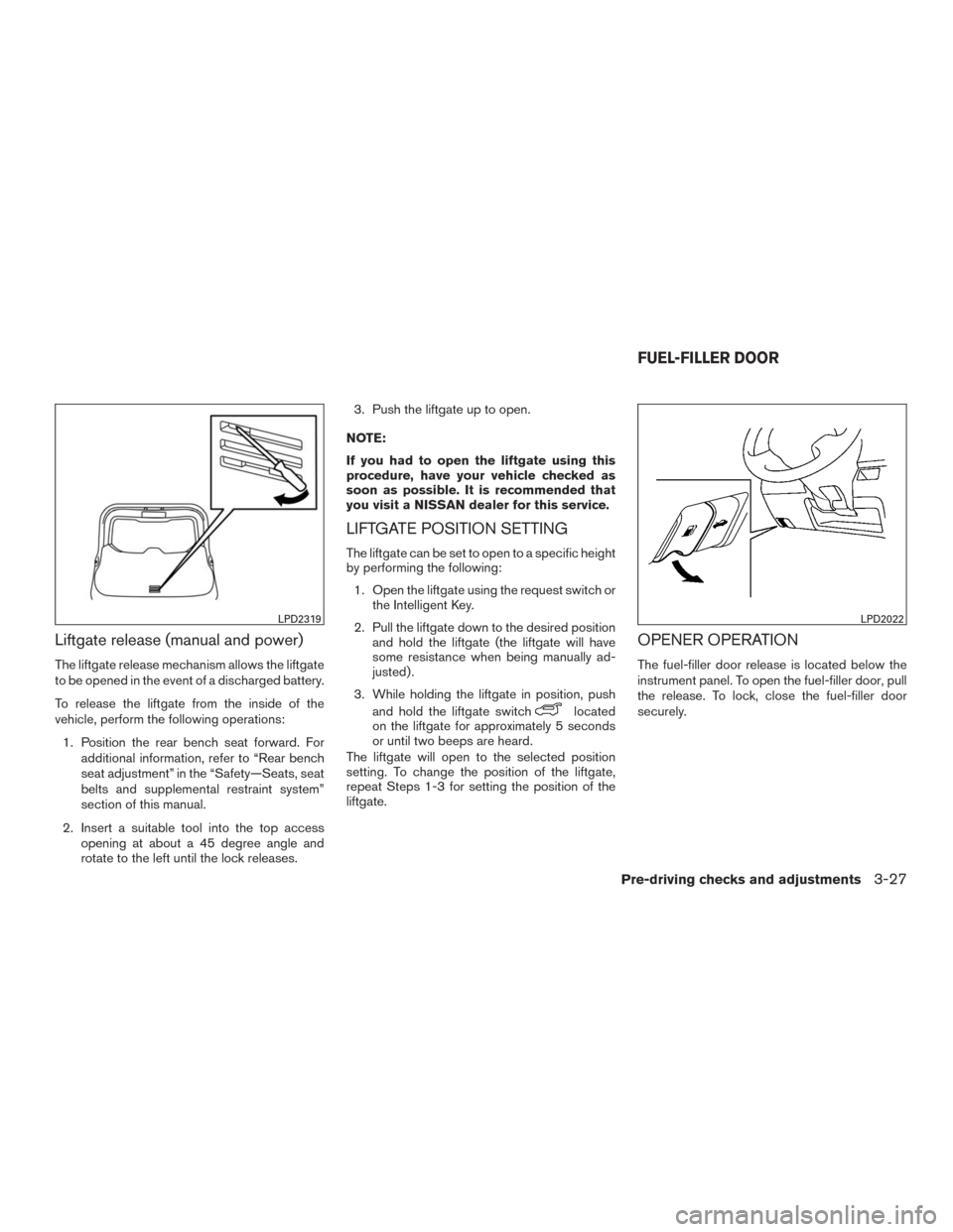
Liftgate release (manual and power)
The liftgate release mechanism allows the liftgate
to be opened in the event of a discharged battery.
To release the liftgate from the inside of the
vehicle, perform the following operations:
1. Position the rear bench seat forward. For
additional information, refer to “Rear bench
seat adjustment” in the “Safety—Seats, seat
belts and supplemental restraint system”
section of this manual.
2. Insert a suitable tool into the top access
opening at about a 45 degree angle and
rotate to the left until the lock releases.3. Push the liftgate up to open.
NOTE:
If you had to open the liftgate using this
procedure, have your vehicle checked as
soon as possible. It is recommended that
you visit a NISSAN dealer for this service.
LIFTGATE POSITION SETTING
The liftgate can be set to open to a specific height
by performing the following:
1. Open the liftgate using the request switch or
the Intelligent Key.
2. Pull the liftgate down to the desired position
and hold the liftgate (the liftgate will have
some resistance when being manually ad-
justed) .
3. While holding the liftgate in position, push
and hold the liftgate switch
located
on the liftgate for approximately 5 seconds
or until two beeps are heard.
The liftgate will open to the selected position
setting. To change the position of the liftgate,
repeat Steps 1-3 for setting the position of the
liftgate.
OPENER OPERATION
The fuel-filler door release is located below the
instrument panel. To open the fuel-filler door, pull
the release. To lock, close the fuel-filler door
securely.
LPD2319LPD2022
FUEL-FILLER DOOR
Pre-driving checks and adjustments3-27
Page 186 of 465
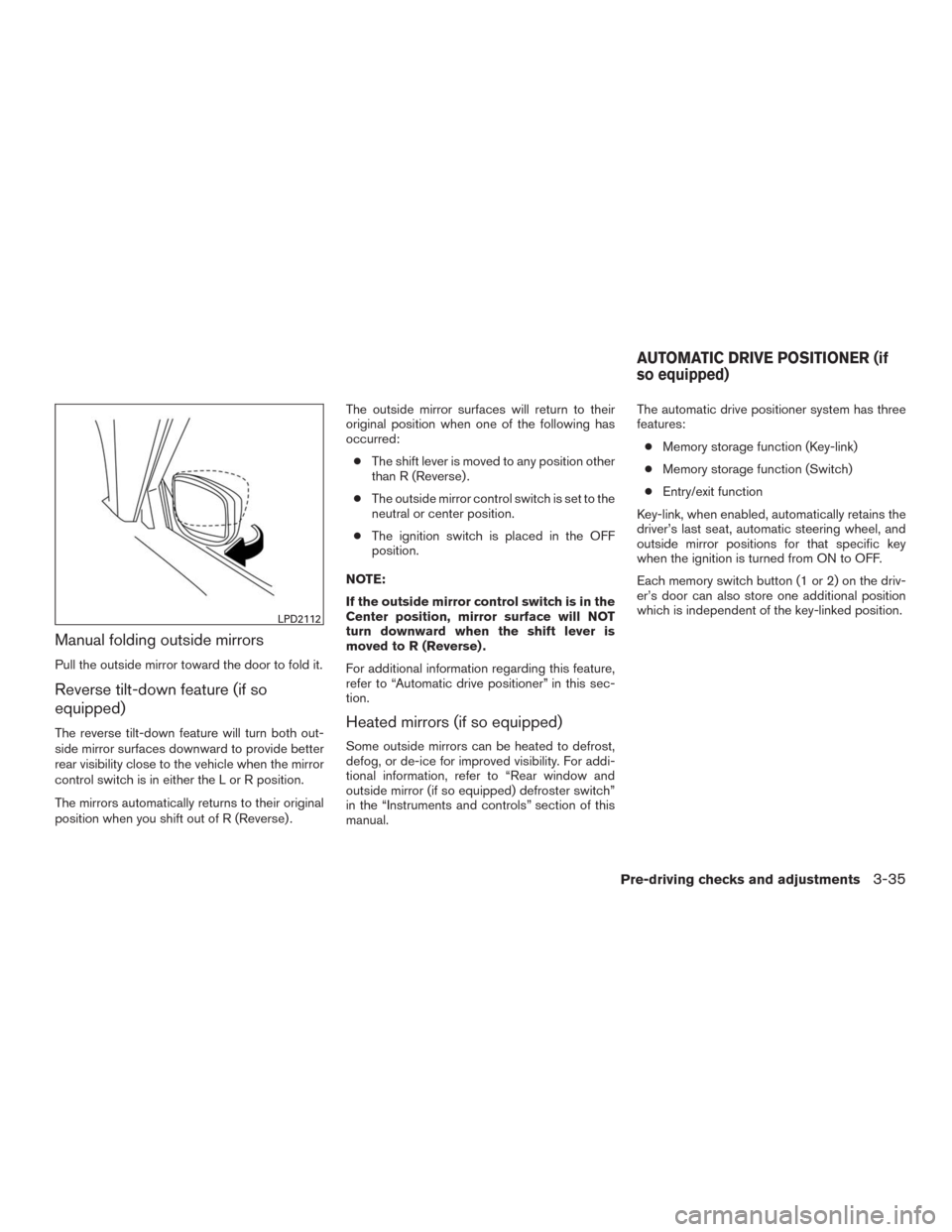
Manual folding outside mirrors
Pull the outside mirror toward the door to fold it.
Reverse tilt-down feature (if so
equipped)
The reverse tilt-down feature will turn both out-
side mirror surfaces downward to provide better
rear visibility close to the vehicle when the mirror
control switch is in either the L or R position.
The mirrors automatically returns to their original
position when you shift out of R (Reverse) .The outside mirror surfaces will return to their
original position when one of the following has
occurred:
●The shift lever is moved to any position other
than R (Reverse) .
●The outside mirror control switch is set to the
neutral or center position.
●The ignition switch is placed in the OFF
position.
NOTE:
If the outside mirror control switch is in the
Center position, mirror surface will NOT
turn downward when the shift lever is
moved to R (Reverse) .
For additional information regarding this feature,
refer to “Automatic drive positioner” in this sec-
tion.Heated mirrors (if so equipped)
Some outside mirrors can be heated to defrost,
defog, or de-ice for improved visibility. For addi-
tional information, refer to “Rear window and
outside mirror (if so equipped) defroster switch”
in the “Instruments and controls” section of this
manual.The automatic drive positioner system has three
features:
●Memory storage function (Key-link)
●Memory storage function (Switch)
●Entry/exit function
Key-link, when enabled, automatically retains the
driver’s last seat, automatic steering wheel, and
outside mirror positions for that specific key
when the ignition is turned from ON to OFF.
Each memory switch button (1 or 2) on the driv-
er’s door can also store one additional position
which is independent of the key-linked position.
LPD2112
AUTOMATIC DRIVE POSITIONER (if
so equipped)
Pre-driving checks and adjustments3-35
Page 187 of 465
MEMORY STORAGE FUNCTION
(Key-Link)
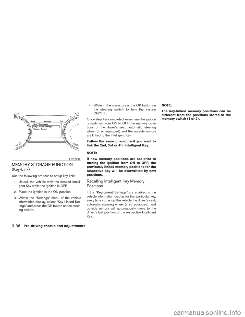
Use the following process to setup key-link:
1. Unlock the vehicle with the desired Intelli-
gent Key while the ignition is OFF.
2. Place the ignition in the ON position.
3. Within the “Settings” menu of the vehicle
information display, select “Key-Linked Set-
tings” and press the OK button on the steer-
ing switch.4. While in the menu, press the OK button on
the steering switch to turn the system
ON/OFF.
Once step 4 is completed, every time the ignition
is switched from ON to OFF, the memory posi-
tions of the driver’s seat, automatic steering
wheel (if so equipped) and the outside mirrors
are linked to the Intelligent Key.
Follow the same procedure if you want to
link the 2nd, 3rd or 4th Intelligent Key.
NOTE:
If new memory positions are set prior to
turning the ignition from ON to OFF, the
previously linked memory positions for the
respective key will be overwritten by new
positions.
Recalling Intelligent Key Memory
Positions
If the “Key-Linked Settings” are enabled in the
vehicle information display for that particular key,
every time you enter the vehicle the driver’s seat,
automatic steering wheel (if so equipped) , and
outside mirrors will automatically move to the
driver’s last position of the respective Intelligent
Key.NOTE:
The key-linked memory positions can be
different from the positions stored in the
memory switch (1 or 2) .
LPD2432
3-36Pre-driving checks and adjustments
Page 189 of 465
SYSTEM OPERATION
The automatic drive positioner system will not
work or will stop operating under the following
conditions:
●When the vehicle speed is above 0 mph
(0 km/h) or 4 mph (7 km/h) for some limited
functions such as linking a key fob to the
meter when the power source is turned on
from off or during the Exit function.
●When any of the memory switches are
pushed while the automatic drive positioner
is operating.
●When the adjusting switch for the driver’s
seat and steering column is turned on while
the automatic drive positioner is operating.
●When the seat has already been moved to
the memorized position.
●When no seat position is stored in the
memory switch.
●When the shift lever is moved from P (Park)
to any other position.
3-38Pre-driving checks and adjustments
Page 198 of 465
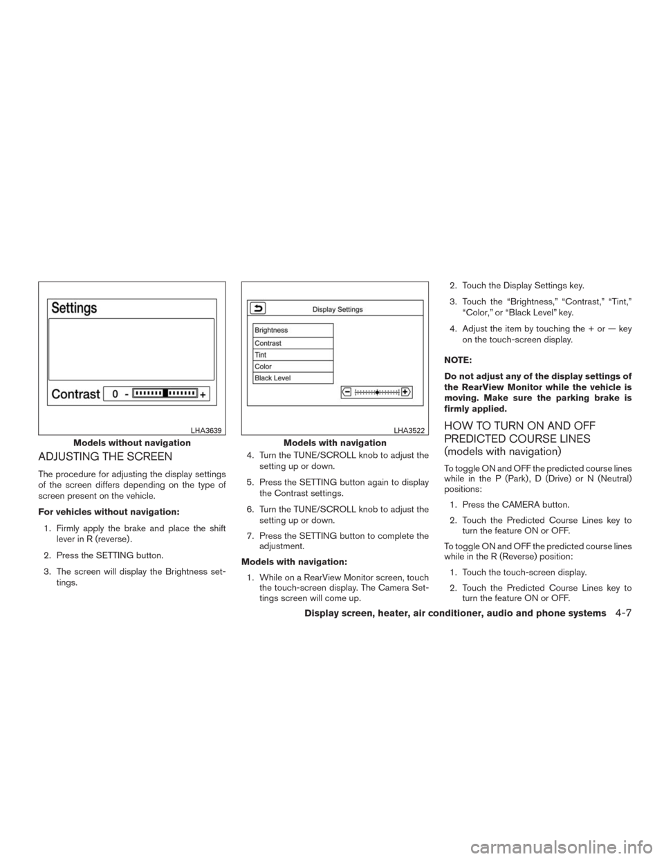
ADJUSTING THE SCREEN
The procedure for adjusting the display settings
of the screen differs depending on the type of
screen present on the vehicle.
For vehicles without navigation:
1. Firmly apply the brake and place the shift
lever in R (reverse) .
2. Press the SETTING button.
3. The screen will display the Brightness set-
tings.4. Turn the TUNE/SCROLL knob to adjust the
setting up or down.
5. Press the SETTING button again to display
the Contrast settings.
6. Turn the TUNE/SCROLL knob to adjust the
setting up or down.
7. Press the SETTING button to complete the
adjustment.
Models with navigation:
1. While on a RearView Monitor screen, touch
the touch-screen display. The Camera Set-
tings screen will come up.2. Touch the Display Settings key.
3. Touch the “Brightness,” “Contrast,” “Tint,”
“Color,” or “Black Level” key.
4. Adjust the item by touching the + or — key
on the touch-screen display.
NOTE:
Do not adjust any of the display settings of
the RearView Monitor while the vehicle is
moving. Make sure the parking brake is
firmly applied.
HOW TO TURN ON AND OFF
PREDICTED COURSE LINES
(models with navigation)
To toggle ON and OFF the predicted course lines
while in the P (Park) , D (Drive) or N (Neutral)
positions:
1. Press the CAMERA button.
2. Touch the Predicted Course Lines key to
turn the feature ON or OFF.
To toggle ON and OFF the predicted course lines
while in the R (Reverse) position:
1. Touch the touch-screen display.
2. Touch the Predicted Course Lines key to
turn the feature ON or OFF.
Models without navigation
LHA3639
Models with navigation
LHA3522
Display screen, heater, air conditioner, audio and phone systems4-7
Page 209 of 465
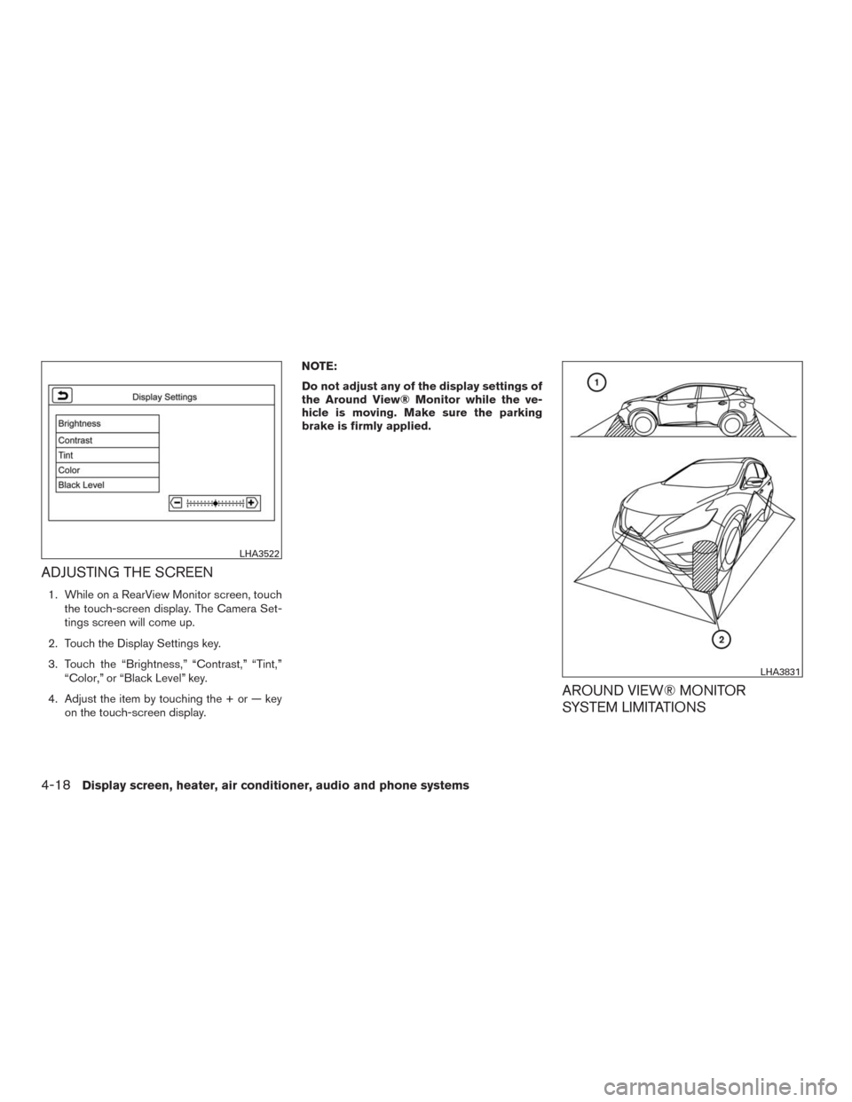
ADJUSTING THE SCREEN
1. While on a RearView Monitor screen, touch
the touch-screen display. The Camera Set-
tings screen will come up.
2. Touch the Display Settings key.
3. Touch the “Brightness,” “Contrast,” “Tint,”
“Color,” or “Black Level” key.
4. Adjust the item by touching the + or — key
on the touch-screen display.NOTE:
Do not adjust any of the display settings of
the Around View® Monitor while the ve-
hicle is moving. Make sure the parking
brake is firmly applied.
AROUND VIEW® MONITOR
SYSTEM LIMITATIONS
LHA3522
LHA3831
4-18Display screen, heater, air conditioner, audio and phone systems
Page 255 of 465
5 Starting and driving
Precautions when starting and driving................5-2
Exhaust gas (carbon monoxide)..................5-2
Three-way catalyst..............................5-2
Tire Pressure Monitoring System (TPMS)..........5-3
On-pavement and off-road driving
precautions....................................5-7
Avoiding collision and rollover . ...................5-7
Off-road recovery...............................5-7
Rapid air pressure loss..........................5-8
Drinking alcohol/drugs and driving................5-8
Driving safety precautions.......................5-9
Push-Button Ignition Switch.......................5-11
Operating range...............................5-12
Push-button ignition switch positions . . ..........5-12
Emergency engine shut off.....................5-13
NISSAN Intelligent Key® battery discharge.......5-13
NISSAN Vehicle Immobilizer System.............5-14
Before starting the engine.........................5-14
Starting the engine...............................5-15
Remote start (if so equipped)...................5-15
Driving the vehicle................................5-16
Continuously Variable Transmission (CVT)........5-16
Parking brake....................................5-21Blind Spot Warning (BSW) (if so equipped).........5-21
BSW system operation........................5-23
How to enable/disable the BSW system.........5-24
BSW system limitations........................5-25
BSW driving situations.........................5-26
System temporarily unavailable..................5-29
System maintenance...........................5-30
Rear Cross Traffic Alert (RCTA) (if so equipped).....5-31
RCTA system operation........................5-32
How to enable/disable the RCTA system.........5-34
RCTA system limitations........................5-35
System temporarily unavailable..................5-38
System maintenance...........................5-38
Cruise control (if so equipped) . ....................5-39
Precautions on cruise control...................
5-39
Cruise control operations.......................5-40
Intelligent Cruise Control (ICC) (if so equipped)......5-41
ICC system operation..........................5-42
The ICC switch...............................5-44
ICC system limitations.........................5-50
System temporarily unavailable..................5-53
System maintenance...........................5-55
Forward Emergency Braking (FEB) (if so equipped) . . 5-56