2016 NISSAN 370Z COUPE engine
[x] Cancel search: enginePage 84 of 428
.When the vehicle is stopped.
. When the ignition switch is ON.
. When the trunk is closed.
. When the shift lever is in a position other
than the R (Reverse) position.
CAUTION
Operate the soft top with the engine
running to prevent a discharged battery.
When the soft top is operating, if any of the
above conditions are discontinued or any of the
following conditions are met, the top will stop
operating.
. When the shift lever is in the R (Reverse)
position.
. When the vehicle moves at a speed of 3
MPH (5 km/h) or more.
. When the battery voltage is extremely low.
. When the temperature of the soft top
system becomes extremely high.
Release the operating switch, and push it again
under the above conditions until the top is fully
opened or closed. The soft top indicator light will
turn off when the top operation is completely
finished.
If the soft top indicator light illuminates with the ignition switch ON, it may indicate the electric
soft top control unit is not functioning properly.
Have your vehicle checked by a NISSAN dealer
as soon as possible.
For more details about the electric soft top
operation, see “Soft top (Roadster models)”
(P.3-21) .SynchroRev Match mode (S-
MODE) indicator (if so equipped)
This indicator will illuminate when the
SynchroRev Match mode (S-MODE) is acti-
vated. (See “SynchroRev Match mode (S-
MODE) (if so equipped for Manual Transmission
models)” (P.5-17) .)
Transmission position indicator (if
so equipped)
When the ignition switch is pushed to the ON
position, the indicator shows the transmission
position.
For AT models:
In the manual shift mode, when the transmission
does not shift to the selected gear due to the
transmission protection mode, the AT position
indicator light will blink and a buzzer will sound.
(See “Driving the vehicle” (P.5-12) .)
Turn signal/hazard indicator lights
The light flashes when the turn signal switch
lever or hazard switch is turned on.
Vehicle Dynamic Control (VDC) off
indicator light
When the ignition switch is in the ON position,
the Vehicle Dynamic Control (VDC) off indicator
light illuminates and then turns off.
The light comes on when the VDC off switch is
pushed to OFF. This indicates that the VDC
system and traction control system are not
operating.
AUDIBLE REMINDERS
Key reminder chime
A chime will sound if the driver side door is
opened while the ignition switch is pushed to
the ACC position or pushed to the OFF or
LOCK position with the Intelligent Key left in the
Intelligent Key port. Make sure the ignition
switch is pushed to the OFF position, and take
the Intelligent Key with you when leaving the
vehicle.
Instruments and controls2-17
Page 86 of 428
JVI0351X
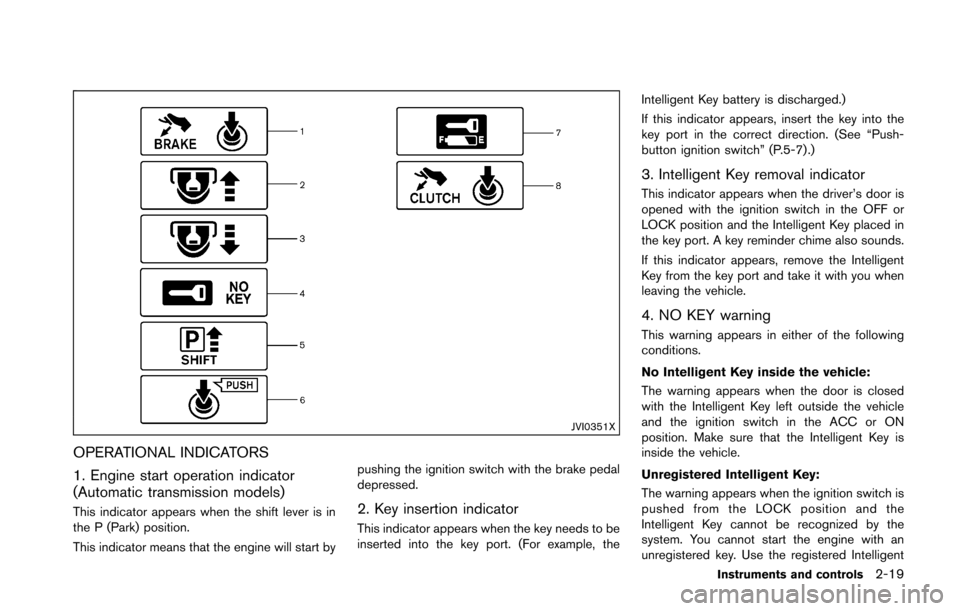
OPERATIONAL INDICATORS
1. Engine start operation indicator
(Automatic transmission models)
This indicator appears when the shift lever is in
the P (Park) position.
This indicator means that the engine will start bypushing the ignition switch with the brake pedal
depressed.2. Key insertion indicator
This indicator appears when the key needs to be
inserted into the key port. (For example, theIntelligent Key battery is discharged.)
If this indicator appears, insert the key into the
key port in the correct direction. (See “Push-
button ignition switch” (P.5-7).)
3. Intelligent Key removal indicator
This indicator appears when the driver’s door is
opened with the ignition switch in the OFF or
LOCK position and the Intelligent Key placed in
the key port. A key reminder chime also sounds.
If this indicator appears, remove the Intelligent
Key from the key port and take it with you when
leaving the vehicle.
4. NO KEY warning
This warning appears in either of the following
conditions.
No Intelligent Key inside the vehicle:
The warning appears when the door is closed
with the Intelligent Key left outside the vehicle
and the ignition switch in the ACC or ON
position. Make sure that the Intelligent Key is
inside the vehicle.
Unregistered Intelligent Key:
The warning appears when the ignition switch is
pushed from the LOCK position and the
Intelligent Key cannot be recognized by the
system. You cannot start the engine with an
unregistered key. Use the registered Intelligent
Instruments and controls2-19
Page 87 of 428
2-20Instruments and controls
Key.
See “Intelligent Key system” (P.3-6) for more
details.
5. SHIFT “P” warning (Automatic Trans-
mission models)
This warning appears when the ignition switch is
pushed to stop the engine with the shift lever in
any position except the P (Park) position.
If this warning appears, move the shift lever to
the P (Park) position or push the ignition switch
to the ON position.
An inside warning chime will also sound. (See
“Intelligent Key system” (P.3-6) .)
6. “PUSH” warning (Automatic Trans-
mission models)
This warning appears when the shift lever is
moved to the P (Park) position with the ignition
switch in the ACC position after the SHIFT “P”
warning appears.
To push the ignition switch to the OFF position,
perform the following procedure:
SHIFT “P” warning?(Move the shift lever to
“P”) ?PUSH warning ?(Push the ignition
switch ?ignition switch position is turned to
ON) ?PUSH warning ?(Push the ignition
switch ?ignition switch position is turned to
OFF)
7. Intelligent Key battery discharge in-
dicator
This indicator appears when the Intelligent Key
battery is running out of power.
If this indicator appears, replace the battery with
a new one. (See “Intelligent Key battery replace-
ment” (P.8-24) .)
8. Engine start operation indicator
(Manual Transmission models)
This indicator means that the engine will start by
pushing the ignition switch with the clutch pedal
depressed.
Page 89 of 428
2-22Instruments and controls
3) and “Tire Pressure Monitoring System
(TPMS)” (P.6-3) .
7. “TIMER” indicator
This indicator appears when the set “TIMER”
indicator activates. You can set the time for up to
6 hours. (See “Trip computer” (P.2-23) .)
8. Low outside temperature warning
This warning appears if the outside temperature
is below 378F(38C) . The warning can be set not
to be displayed. (See “Trip computer” (P.2-23) .)
9. SynchroRev Match mode (S-MODE)
warning
This warning appears if a system malfunction
occurs. When the warning appears, the S-
MODE function will not operate, but the manual
transmission will operate normally and driving
can be continued. Have the system checked by
a NISSAN dealer.
10. Extended storage fuse warning
This warning may appear if the extended storage
fuse switch is not pushed in (switched on) .
When this warning appears, push in (switch on)
the extended storage fuse switch to turn off the
warning. For more information, see “Extended
storage fuse switch” (P.8-23) .
SIC4237
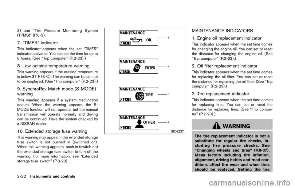
MAINTENANCE INDICATORS
1. Engine oil replacement indicator
This indicator appears when the set time comes
for changing the engine oil. You can set or reset
the distance for changing the engine oil. (See
“Trip computer” (P.2-23) .)
2. Oil filter replacement indicator
This indicator appears when the set time comes
for replacing the oil filter. You can set or reset
the distance for replacing the oil filter. (See “Trip
computer” (P.2-23).)
3. Tire replacement indicator
This indicator appears when the set time comes
for replacing tires. You can set or reset the
distance for replacing tires. (See “Trip compu-
ter” (P.2-23) .)
WARNING
The tire replacement indicator is not a
substitute for regular tire checks, in-
cluding tire pressure checks. See
“Changing wheels and tires” (P.8-37) .
Many factors including tire inflation,
alignment, driving habits and road con-
ditions affect tire wear and when tires
should be replaced. Setting the tire
Page 90 of 428
replacement indicator for a certain
driving distance does not mean your
tires will last that long. Use the tire
replacement indicator as a guide only
and always perform regular tire checks.
Failure to perform regular tire checks,
including tire pressure checks could
result in tire failure. Serious vehicle
damage could occur and may lead to a
collision, which could result in serious
personal injury or death.
4. “OTHER” indicator
This indicator appears when the set time comes
for replacing items other than the engine oil, oil
filter and tires. You can set or reset the distance
for replacing the items. (See “Trip computer”
(P.2-23) .)
Models with navigation system:
More maintenance reminders are also available
on the center display. (See “How to use INFO
button” (P.4-7).)
SIC3978
TRIP COMPUTER
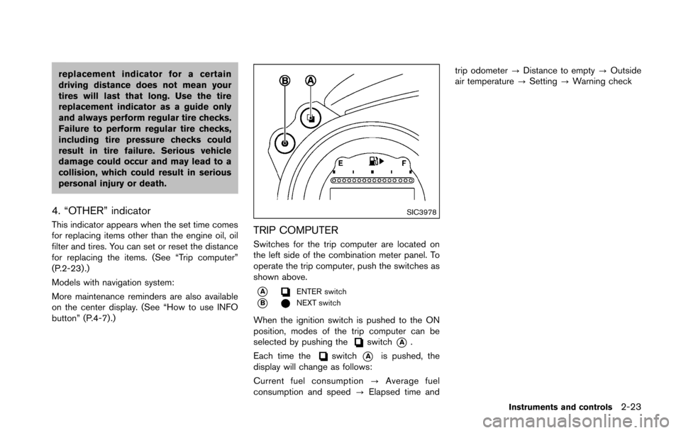
Switches for the trip computer are located on
the left side of the combination meter panel. To
operate the trip computer, push the switches as
shown above.
*AENTER switch
*BNEXT switch
When the ignition switch is pushed to the ON
position, modes of the trip computer can be
selected by pushing the
switch*A.
Each time the
switch*Ais pushed, the
display will change as follows:
Current fuel consumption ?Average fuel
consumption and speed ?Elapsed time and trip odometer
?Distance to empty ?Outside
air temperature ?Setting ?Warning check
Instruments and controls2-23
Page 93 of 428
2-26Instruments and controls
SIC4037
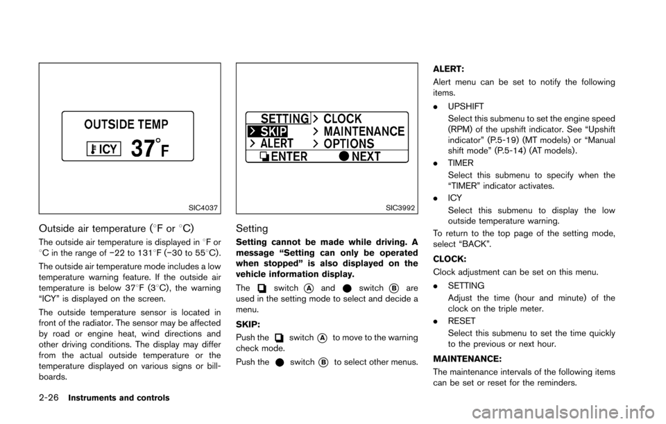
Outside air temperature (8For8C)
The outside air temperature is displayed in 8For
8C in the range of �í22 to 1318F(�í30 to 558C) .
The outside air temperature mode includes a low
temperature warning feature. If the outside air
temperature is below 378F(3 8C) , the warning
“ICY” is displayed on the screen.
The outside temperature sensor is located in
front of the radiator. The sensor may be affected
by road or engine heat, wind directions and
other driving conditions. The display may differ
from the actual outside temperature or the
temperature displayed on various signs or bill-
boards.
SIC3992
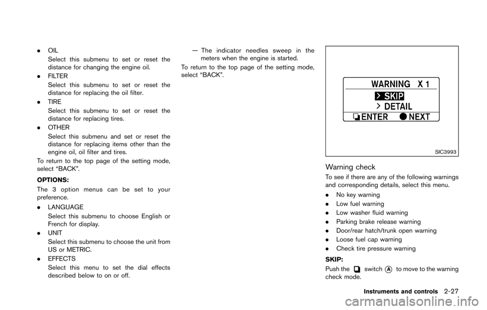
Setting
Setting cannot be made while driving. A
message “Setting can only be operated
when stopped” is also displayed on the
vehicle information display.
The
switch*Aandswitch*Bare
used in the setting mode to select and decide a
menu.
SKIP:
Push the
switch*Ato move to the warning
check mode.
Push the
switch*Bto select other menus. ALERT:
Alert menu can be set to notify the following
items.
.
UPSHIFT
Select this submenu to set the engine speed
(RPM) of the upshift indicator. See “Upshift
indicator” (P.5-19) (MT models) or “Manual
shift mode” (P.5-14) (AT models) .
. TIMER
Select this submenu to specify when the
“TIMER” indicator activates.
. ICY
Select this submenu to display the low
outside temperature warning.
To return to the top page of the setting mode,
select “BACK”.
CLOCK:
Clock adjustment can be set on this menu.
. SETTING
Adjust the time (hour and minute) of the
clock on the triple meter.
. RESET
Select this submenu to set the time quickly
to the previous or next hour.
MAINTENANCE:
The maintenance intervals of the following items
can be set or reset for the reminders.
Page 94 of 428
.OIL
Select this submenu to set or reset the
distance for changing the engine oil.
. FILTER
Select this submenu to set or reset the
distance for replacing the oil filter.
. TIRE
Select this submenu to set or reset the
distance for replacing tires.
. OTHER
Select this submenu and set or reset the
distance for replacing items other than the
engine oil, oil filter and tires.
To return to the top page of the setting mode,
select “BACK”.
OPTIONS:
The 3 option menus can be set to your
preference.
. LANGUAGE
Select this submenu to choose English or
French for display.
. UNIT
Select this submenu to choose the unit from
US or METRIC.
. EFFECTS
Select this menu to set the dial effects
described below to on or off. — The indicator needles sweep in the
meters when the engine is started.
To return to the top page of the setting mode,
select “BACK”.
SIC3993
Warning check
To see if there are any of the following warnings
and corresponding details, select this menu.
. No key warning
. Low fuel warning
. Low washer fluid warning
. Parking brake release warning
. Door/rear hatch/trunk open warning
. Loose fuel cap warning
. Check tire pressure warning
SKIP:
Push the
switch*Ato move to the warning
check mode.
Instruments and controls2-27
Page 96 of 428
SIC2045
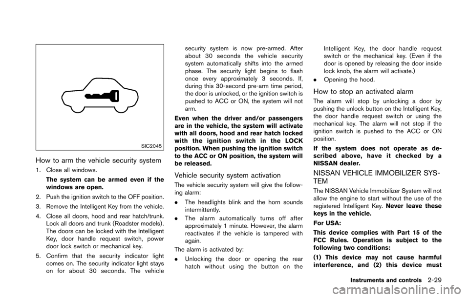
How to arm the vehicle security system
1. Close all windows.The system can be armed even if the
windows are open.
2. Push the ignition switch to the OFF position.
3. Remove the Intelligent Key from the vehicle.
4. Close all doors, hood and rear hatch/trunk. Lock all doors and trunk (Roadster models) .
The doors can be locked with the Intelligent
Key, door handle request switch, power
door lock switch or mechanical key.
5. Confirm that the security indicator light comes on. The security indicator light stays
on for about 30 seconds. The vehicle security system is now pre-armed. After
about 30 seconds the vehicle security
system automatically shifts into the armed
phase. The security light begins to flash
once every approximately 3 seconds. If,
during this 30-second pre-arm time period,
the door is unlocked, or the ignition switch is
pushed to ACC or ON, the system will not
arm.
Even when the driver and/or passengers
are in the vehicle, the system will activate
with all doors, hood and rear hatch locked
with the ignition switch in the LOCK
position. When pushing the ignition switch
to the ACC or ON position, the system will
be released.Vehicle security system activation
The vehicle security system will give the follow-
ing alarm:
. The headlights blink and the horn sounds
intermittently.
. The alarm automatically turns off after
approximately 1 minute. However, the alarm
reactivates if the vehicle is tampered with
again.
The alarm is activated by:
. Unlocking the door or opening the rear
hatch without using the button on the Intelligent Key, the door handle request
switch or the mechanical key. (Even if the
door is opened by releasing the door inside
lock knob, the alarm will activate.)
. Opening the hood.
How to stop an activated alarm
The alarm will stop by unlocking a door by
pushing the unlock button on the Intelligent Key,
the door handle request switch or using the
mechanical key. The alarm will not stop if the
ignition switch is pushed to the ACC or ON
position.
If the system does not operate as de-
scribed above, have it checked by a
NISSAN dealer.
NISSAN VEHICLE IMMOBILIZER SYS-
TEM
The NISSAN Vehicle Immobilizer System will not
allow the engine to start without the use of the
registered Intelligent Key. Never leave these
keys in the vehicle.
For USA:
This device complies with Part 15 of the
FCC Rules. Operation is subject to the
following two conditions:
(1) This device may not cause harmful
interference, and (2) this device must
Instruments and controls2-29