2016 MITSUBISHI OUTLANDER spare wheel
[x] Cancel search: spare wheelPage 391 of 464
How to change a tire
For emergencies 8-9
8
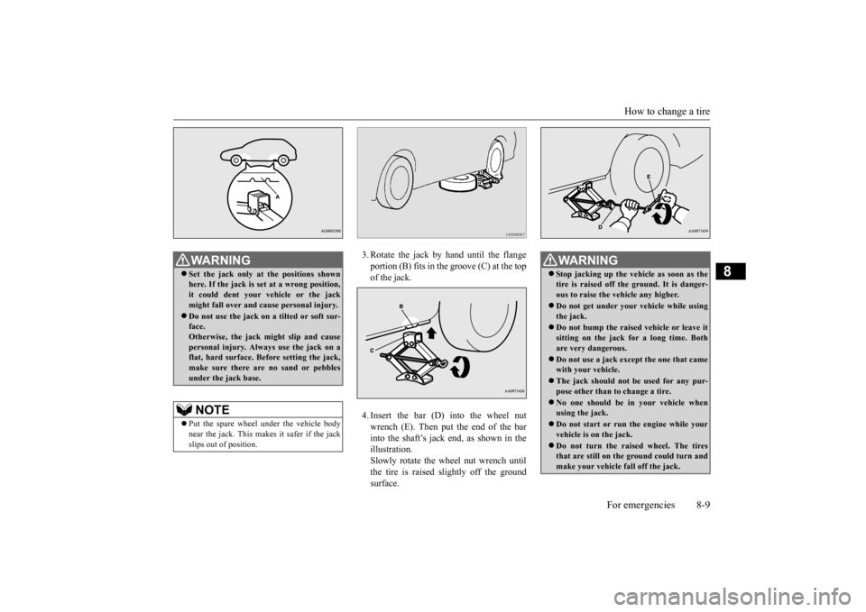
3. Rotate the jack by hand until the flange portion (B) fits in the groove (C) at the top of the jack. 4. Insert the bar (D) into the wheel nut wrench (E). Then put the end of the bar into the shaft’s jack end, as shown in the illustration.Slowly rotate the wheel nut wrench until the tire is raised slightly off the ground surface.
WA R N I N G Set the jack only at
the positions shown
here. If the jack is se
t at a wrong position,
it could dent your vehicle or the jack might fall over and ca
use personal injury.
Do not use the jack on a tilted or soft sur- face. Otherwise, the jack might slip and causepersonal injury. Always
use the jack on a
flat, hard surface. Before setting the jack, make sure there are no sand or pebblesunder the jack base.NOTE
Put the spare wheel under the vehicle body near the jack. This makes it safer if the jack slips out of position.
WA R N I N G Stop jacking up the ve
hicle as soon as the
tire is raised off the ground. It is danger-ous to raise the ve
hicle any higher.
Do not get under your vehicle while using the jack. Do not bump the raised
vehicle or leave it
sitting on the jack for a long time. Both are very dangerous. Do not use a jack except the one that came with your vehicle. The jack should not
be used for any pur-
pose other than to change a tire. No one should be
in your vehicle when
using the jack. Do not start or run
the engine while your
vehicle is on the jack. Do not turn the raised wheel. The tires that are still on the ground could turn and make your vehicle fall off the jack.
BK0223400US.book 9 ページ 2015年2月13日 金曜日 午後12時15分
Page 392 of 464
How to change a tire 8-10 For emergencies
8
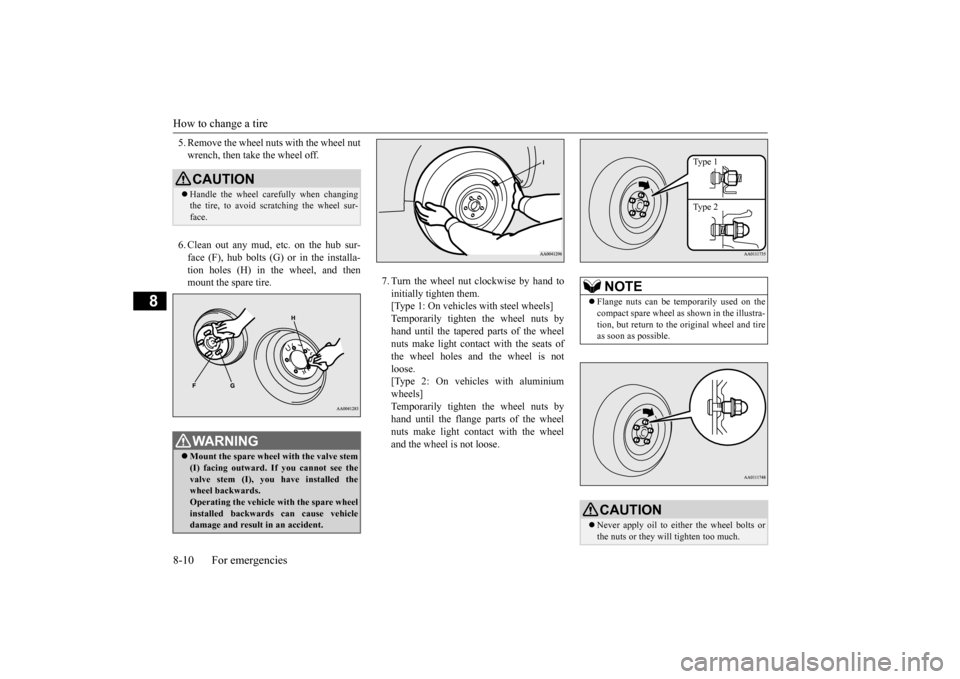
5. Remove the wheel nuts with the wheel nut wrench, then take the wheel off. 6. Clean out any mud, etc. on the hub sur- face (F), hub bolts (G)
or in the installa-
tion holes (H) in the wheel, and then mount the spare tire.
7. Turn the wheel nut clockwise by hand to initially tighten them. [Type 1: On vehicles
with steel wheels]
Temporarily tighten the wheel nuts by hand until the tapered parts of the wheel nuts make light contac
t with the seats of
the wheel holes and the wheel is not loose. [Type 2: On vehicles with aluminiumwheels] Temporarily tighten the wheel nuts by hand until the flange parts of the wheelnuts make light cont
act with the wheel
and the wheel is not loose.
CAUTION Handle the wheel carefully when changing the tire, to avoid scratching the wheel sur- face.WA R N I N G Mount the spare wheel with the valve stem (I) facing outward. If
you cannot see the
valve stem (I), you
have installed the
wheel backwards.Operating the vehicle with the spare wheel installed backwards can cause vehicle damage and result
in an ac
cident.
NOTE
Flange nuts can be te
mporarily used on the
compact spare wheel as shown in the illustra- tion, but return to the original wheel and tire as soon as possible.CAUTION Never apply oil to either the wheel bolts or the nuts or they will tighten too much.
Type 1 Type 2
BK0223400US.book 10 ページ 2015年2月13日 金曜日 午後12時15分
Page 394 of 464
How to change a tire 8-12 For emergencies
8
N00832300020
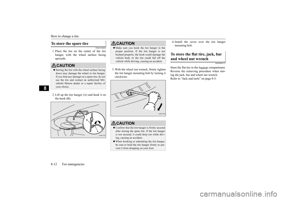
1. Place the tire on the center of the tire hanger, with the wheel surface facing upwards. 2. Lift up the tire hanger (A) and hook it on the hook (B).
3. With the wheel nut wrench, firmly tighten the tire hanger mounti
ng bolt by turning it
clockwise.
4. Install the cover over the tire hanger mounting bolt.
N00850001172
Store the flat tire in the luggage compartment.Reverse the removing procedure when stor- ing the jack, bar and wheel nut wrench. Refer to “Jack and t
ools” on page 8-5.
To store the spare tire
CAUTIONStoring the tire with the wheel surface facing down may damage the wheel or tire hanger. If you find any damage
on a spare tire, do not
use the tire and contact an authorized Mit- subishi Motors dealer or a repair facility of your choice.
CAUTION Make sure you hook the tire hanger in the proper position. If the tire hanger is nothooked properly, the hook
could damage the
vehicle body or the tire
could fall off the
vehicle while driving,
causing an accident.
CAUTIONConfirm that the tire hanger is firmly secured after storing the spare
tire. If the tire hanger
is not secured, it c
ould drop out while driv-
ing, causing
an accident.
When hooking or unhooking the tire hanger, be sure to hold the tire hanger firmly to pre-vent it from dropping on your foot.
To store the flat tire, jack, bar and wheel nut wrench
BK0223400US.book 12 ページ 2015年2月13日 金曜日 午後12時15分
Page 417 of 464
Tires
Vehicle care and maintenance 9-19
9
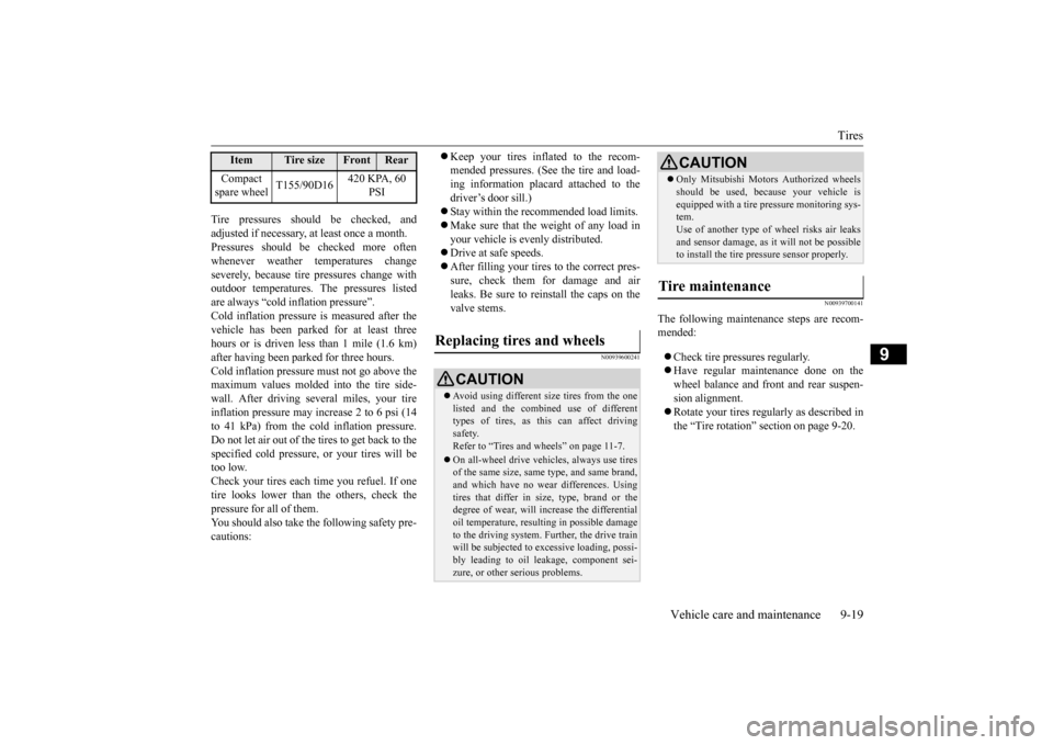
Tire pressures should be checked, and adjusted if necessary, at least once a month.Pressures should be checked more often whenever weather temperatures change severely, becaus
e tire pressures change with
outdoor temperatures. The pressures listed are always “cold inflation pressure”. Cold inflation pressure is measured after thevehicle has been parked
for at least three
hours or is driven less than 1 mile (1.6 km) after having been parked for three hours. Cold inflation pressure
must not go above the
maximum values molded into the tire side-wall. After driving se
veral miles, your tire
inflation pressure may increase 2 to 6 psi (14 to 41 kPa) from the cold inflation pressure.Do not let air out of the tires to get back to the specified cold pressure, or your tires will be too low.Check your tires each t
ime you refuel. If one
tire looks lower than the others, check the pressure for all of them.You should also take the following safety pre- cautions:
Keep your tires inflated to the recom- mended pressures. (See the tire and load-ing information placard attached to the driver’s door sill.) Stay within the recommended load limits. Make sure that the weight of any load in your vehicle is evenly distributed. Drive at safe speeds. After filling your tires to the correct pres- sure, check them for damage and air leaks. Be sure to reinstall the caps on the valve stems.
N00939600241
N00939700141
The following maintenance steps are recom- mended: Check tire pressures regularly. Have regular maintenance done on the wheel balance and front
and rear suspen-
sion alignment. Rotate your tires regul
arly as described in
the “Tire rotation” section on page 9-20.
Compact spare wheel
T155/90D16
420 KPA, 60
PSI
Item
Tire size
Front
Rear
Replacing tires and wheels
CAUTION Avoid using different size tires from the one listed and the combined use of different types of tires, as this can affect driving safety.Refer to “Tires and wheels” on page 11-7. On all-wheel drive vehi
cles, always use tires
of the same size, same
type, and same brand,
and which have no wear differences. Using tires that differ in size, type, brand or thedegree of wear, will increase the differential oil temperature, resul
ting in possible damage
to the driving system. Further, the drive trainwill be subjected to ex
cessive loading, possi-
bly leading to oil leakage, component sei- zure, or other serious problems.
Only Mitsubishi Motors Authorized wheels should be used, beca
use your vehicle is
equipped with a tire pr
essure monitoring sys-
tem. Use of another type of wheel risks air leaks and sensor damage, as it
will not be possible
to install the tire pressure sensor properly.
Tire maintenance
CAUTION
BK0223400US.book 19 ページ 2015年2月13日 金曜日 午後12時15分
Page 418 of 464
Tires 9-20 Vehicle care and maintenance
9
N00939800184
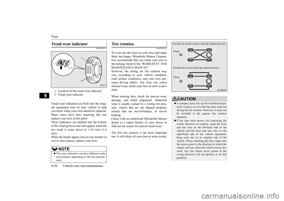
Tread wear indicators are built into the origi- nal equipment tires on your vehicle to helpyou know when your tires should be replaced. Many states have la
ws requiring that you
replace your tires at this point.These indicators are molded into the bottom of the tread grooves and will appear when the tire tread is worn down to 1/16 inch (1.6mm). When the bands appear next to one another in two or more places
, replace your tires.
N00939901528
To even out the wear on your tires and make them last longer, Mitsubishi Motors Corpora- tion recommends that you rotate your tires atthe mileage listed in the “WARRANTY AND MAINTENANCE MANUAL”. However, the timing for tire rotation mayvary according to your vehicle condition, road surface conditions, and your own per- sonal driving habits. Any time you notice unusual wear, rotate your
tires as soon as pos-
sible. When rotating tires, check for uneven wear, damage, and wheel al
ignment. Abnormal
wear is usually caused by a wrong tire pres- sure, wheels that are not aligned properly,wheels that are out-of-balance, or severe braking. Check with an authorized Mitsubishi Motorsdealer or a repair fac
ility of your choice to
find out the reason for uneven tread wear. The first tire rotation is the most important one. It will allow all your tires to wear evenly.
Tread wear indicator 1- Location of the tread wear indicator2- Tread wear indicator
NOTE
Tire wear indicators ca
n have different marks
and locations depending
on the tire manufac-
turer.
Tire rotation
CAUTION A compact spare tire can be installed tempo- rarily in place of a tire
that has been removed
during the tire rotation. However, it must notbe included in the re
gular tire rotation
sequence. If the tires have arrows (A) indicating the correct direction of rotation, swap the front and rear tires on the left-hand side of thevehicle and the front and rear tires on theright-hand side of th
e vehicle separately.
Keep each tire on its original side of the vehicle. When installing the tires, make surethe arrows point in the direction in which the wheels will turn when the vehicle moves for- ward. Any tire whose arrow points in thewrong direction will not
perform to its full
potential.
Tires that do not have arrows showing rotation direction Tires that have arrows s
howing rotation direction
Front Front
BK0223400US.book 20 ページ 2015年2月13日 金曜日 午後12時15分
Page 424 of 464
Fuses 9-26 Vehicle care and maintenance
9
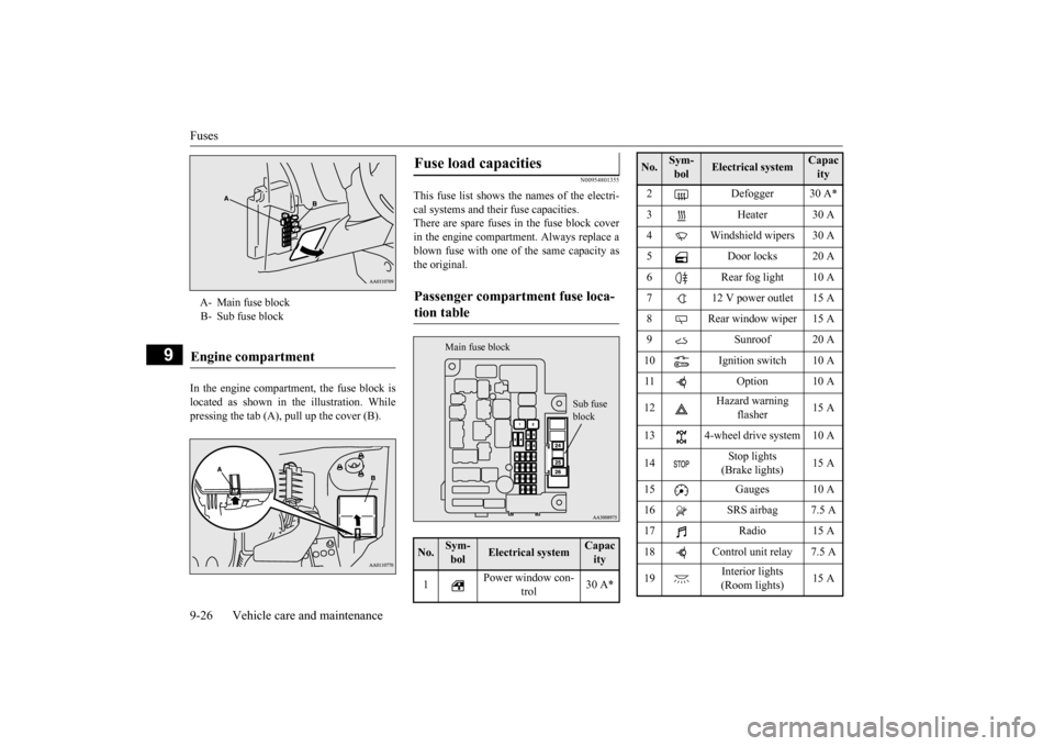
In the engine compartment, the fuse block is located as shown in the illustration. Whilepressing the tab (A), pull up the cover (B).
N00954801355
This fuse list shows the names of the electri- cal systems and their fuse capacities. There are spare fuses in the fuse block coverin the engine compartment. Always replace a blown fuse with one of the same capacity as the original.
A- Main fuse block B- Sub fuse blockEngine compartment
Fuse load capacities Passenger compartment fuse loca- tion table No.
Sym- bol
Electrical system
Capacity
1
Power window con-
trol
30 A*
Sub fuse block
Main fuse block
2 Defogger 30 A* 3 Heater 30 A 4 Windshield wipers 30 A 5 Door locks 20 A6 Rear fog light 10 A7 12 V power outlet 15 A8 Rear window wiper 15 A9 Sunroof 20 A 10 Ignition switch 10 A 11 Option 10 A 12
Hazard warning
flasher
15 A
13 4-wheel drive system 10 A 14
Stop lights (Brake lights)
15 A
15 Gauges 10 A 16 SRS airbag 7.5 A 17 Radio 15 A18 Control unit relay 7.5 A 19
Interior lights (Room lights)
15 A
No.
Sym- bol
Electrical system
Capacity
BK0223400US.book 26 ページ 2015年2月13日 金曜日 午後12時15分