2016 MITSUBISHI OUTLANDER III fuel pump
[x] Cancel search: fuel pumpPage 22 of 464

Filling the fuel tank 3-4 General information
3
All-wheel drive vehicles: 15.8 gal (60 L) Front-wheel drive vehi
cles: 16.6 gal (63 L)
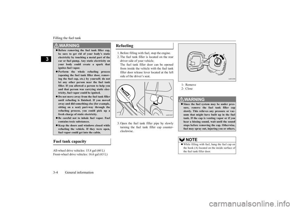
1. Before filling with fuel, stop the engine. 2. The fuel tank filler is located on the rear driver side of your vehicle. The fuel tank filler door can be openedfrom inside the vehicle with the fuel tank filler door release lever located at the left side of the driver’s seat. 3. Open the fuel tank filler pipe by slowly turning the fuel tank filler cap counter- clockwise.
Before removing the fuel tank filler cap, be sure to get rid of your body’s staticelectricity by touching a metal part of thecar or fuel pump. Any
static electricity on
your body could create a spark that ignites fuel vapor. Perform the whole
refueling process
(opening the fuel tank filler door, remov-ing the fuel cap, etc.) by yourself; do not let any other
person near the fuel tank
filler. If you allowed
a person to help you
and that person was ca
rrying static elec-
tricity, fuel vapor could be ignited. Do not move away from
the fuel tank filler
until refueling is fi
nished. If you moved
away and did somethin
g else (for example,
sitting on a seat) part-way through the refueling process, you could pick up a fresh charge of st
atic electricity.
Be careful not to inhale fuel vapor. Fuel contains toxic substances. Keep the doors and wi
ndows closed while
refueling the vehicle. If they were open,fuel vapor could ge
t into the cabin.
Fuel tank capacity
WA R N I N G
Refueling
1- Remove 2- CloseWA R N I N G Since the fuel system may be under pres- sure, remove the fuel tank filler capslowly. This relieves
any pressure or vac-
uum that might have built up in the fuel tank. If the cap is venting vapor or if youhear a hissing sound, wait until the sound stops before removing the cap. Otherwise, fuel may spray out, in
juring you or others.
NOTE
While filling with fuel
, hang the fuel cap on
the hook (A) located on the inside surface ofthe fuel tank filler door.
BK0223400US.book 4 ページ 2015年2月13日 金曜日 午後12時15分
Page 383 of 464

8
For emergenciesIf the vehicle breaks down ...............................................................8-2 Jump-starting the engine ..................................................................8-2 Engine overheating ..........................................................................8-4Jack and tools ...................................................................................8-5 How to change a tire ........................................................................8-6 Towing ...........................................................................................8-14Operation under adverse driving conditions
...........
.........
.........
.....8-15
Fuel Pump Shut-off System ...........................................................8-16
BK0223400US.book 1 ページ 2015年2月13日 金曜日 午後12時15分
Page 398 of 464

Fuel Pump Shut-off System 8-16 For emergencies
8
When driving on a road covered with snow or ice, use s
now tires. Tire chains
cannot be used on your vehicle. There may be state or local regulations aboutusing snow tires. Al
ways check the regu-
lations in your local area before using them. Refer to “Snow tires” on page 9-21and “Tire chains” on page 9-21. Drive slowly. Do not make sudden starts or stops, sharp turns, or slam on the brakes. Allow extra distance
between your vehi-
cle and the vehicle in front of you, and avoid sudden braking. If a skid occurs when the accelerator pedal is depressed, take your foot off the pedal. Steer gently in the direction of the skid. Your vehicle is equipped with an anti-lock braking system (ABS). Hold the brake pedal down firmly and keep it depressed.Do not pump the brake pedal which will result in reduced braking performance. After parking on snowy or icy roads, it may be difficult to move your vehicle due to the brake being frozen. Depress the accelerator pedal little by little to movethe vehicle when safe to do so.
Drive as slow as pos
sible when driving on
bumpy, rutted roads or over potholes.
N00860600031
In the event of a collision causing frontal air-bag deployment, the fuel pump shut-off sys-tem will activate to st
op fuel supply to the
engine.
On snowy or icy roads
CAUTION Do not depress the acce
lerator pedal rapidly.
The vehicle could start moving when itbreaks free from the
ice, possibly resulting in
an accident.
On a bumpy or rutted road
CAUTION Driving on bumpy, rutted roads or over pot- holes can damage th
e tires and wheels.
Wheels with low-profiles tires or under-inflated tires are especially at risk for dam- age.
Fuel Pump Shut-off System
WA R N I N G Before attempting to restart the engine after a collision, alw
ays inspect the ground
under the vehicle for leaking fuel. If a fuelleak is found or a fuel
odor is detected, do
not restart the engine. Mitsubishi Motors recommends that your vehicle be inspected by
an author
ized Mit-
subishi Motors dealer
after any collision.
BK0223400US.book 16 ページ 2015年2月13日 金曜日 午後12時15分
Page 426 of 464

Fuses 9-28 Vehicle care and maintenance
9
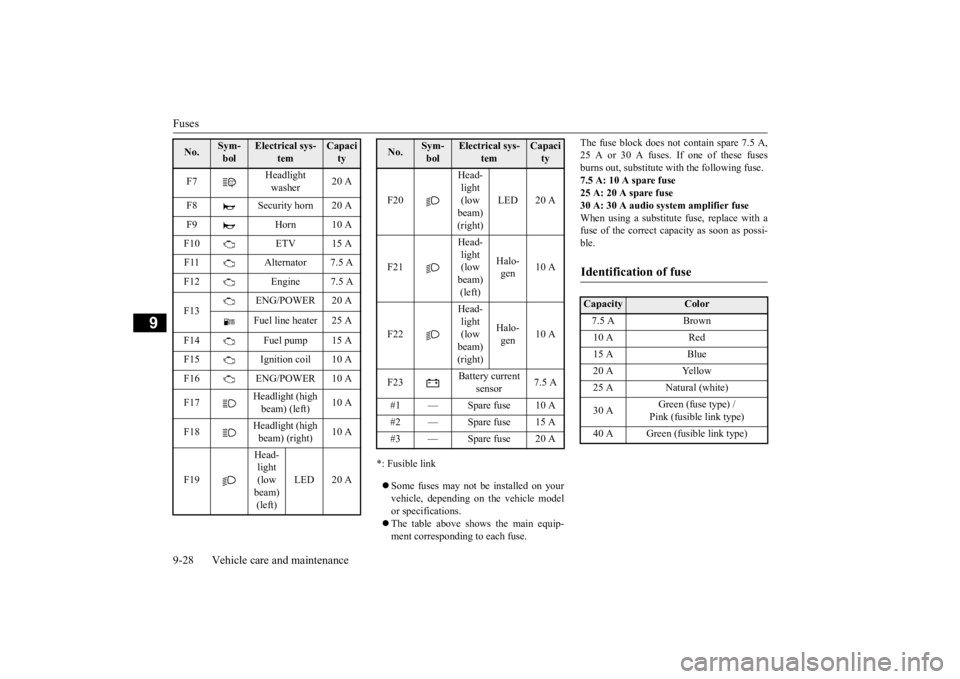
*: Fusible link Some fuses may not be installed on your vehicle, depending on
the vehicle model
or specifications. The table above show
s the main equip-
ment corresponding to each fuse.
The fuse block does not contain spare 7.5 A, 25 A or 30 A fuses. If one of these fusesburns out, substitute wi
th the following fuse.
7.5 A: 10 A spare fuse 25 A: 20 A spare fuse30 A: 30 A audio system amplifier fuse When using a substitute fuse, replace with a fuse of the correct capacity as soon as possi-ble.
F7
Headlight washer
20 A
F8 Security horn 20 A F9 Horn 10 AF10 ETV 15 A F11 Alternator 7.5 A F12 Engine 7.5 A F13
ENG/POWER 20 A Fuel line heater 25 A
F14 Fuel pump 15 A F15 Ignition coil 10 A F16 ENG/POWER 10 A F17
Headlight (high beam) (left)
10 A
F18
Headlight (high beam) (right)
10 A
F19
Head- light (low beam) (left)
LED 20 A
No.
Sym- bol
Electrical sys-
tem
Capacity
F20
Head- light (low beam) (right)
LED 20 A
F21
Head- light (low beam) (left)
Halo- gen
10 A
F22
Head- light (low beam) (right)
Halo- gen
10 A
F23
Battery current
sensor
7.5 A
#1 — Spare fuse 10 A #2 — Spare fuse 15 A #3 — Spare fuse 20 ANo.
Sym- bol
Electrical sys-
tem
Capacity
Identification of fuse Capacity
Color
7.5 A Brown 10 A Red 15 A Blue 20 A Yellow 25 A Natural (white) 30 A
Green (fuse type) / Pink (fusible link type)
40 A Green (fusible link type)
BK0223400US.book 28 ページ 2015年2月13日 金曜日 午後12時15分
Page 459 of 464

Alphabetical index
12-3
12
Front side-marker lights
Bulb capacity
.................................
9-30
Replacement
..................................
9-33
Front turn signal light
Bulb capacity
.................................
9-30
Replacement
..................................
9-34
Fuel
Filling the fuel tank
...........................
3-3
Fuel economy
...................................
6-2
Fuel hoses
......................................
9-23
Fuel selection
...................................
3-2
Tank capacity
.................................
11-7
Fuel Pump Shut-off System
.................
8-16
Fuses
.................................................
9-25
Fusible links
.......................................
9-25
G
General maintenance
...........................
9-23
General vehicle data
............................
11-4
Genuine parts
.......................................
3-6
Glove compartment
...........................
5-229
Glove compartment light
Bulb capacity
.................................
9-32
H
Hazard warning
flasher switch
...........
5-184
Hazard warning lights
.......................
5-172
Head restraints
....................................
4-10
Headlight leveling switch
...................
5-182
Headlights
Bulb capacity
.................................
9-30
Dimmer
........................................
5-180
Headlight flasher
...........................
5-181
Replacement
..........................
9-32
, 9-33
Switch
..........................................
5-177
High beam indicator
..........................
5-172
High-mounted stop light
Bulb capacity
.................................
9-30
Hill start assist
...................................
5-89
HomeLink® Wireless
Control System
.5-220
Hood lock release me
chanism and safety
catch
...............................................
9-25
Horn switch
......................................
5-191
I
If the vehicle breaks down
.....................
8-2
Ignition switch
...................................
5-60
Important facts to know in
case of an accident
10-4 Indicators
....................
5-154
, 5-171
, 5-172
Information screen display
.................
5-155
Inside rearview mirror
.........................
5-55
Inspection and maintena
nce following rough
road operation
..................................
5-87
Instrument cluster
..............................
5-126
Interior lights
....................................
5-225
J
Jack
.....................................................
8-5
Storage
............................................
8-5
Jump-starting the engine
........................
8-2
K
Keyless entry system
....................
5-7
, 5-29
Keys
....................................................
5-3
L
Labeling
.............................................
11-2
Lane Departure Warning System (LDW)
.....
5-116 License plate light
Bulb capacity
.................................
9-30
Replacement
...................................
9-37
Liftgate
..............................................
5-36
Link System
.....................................
5-192
Loading information
..............................
6-6
Lubricants
..........................................
11-7
Luggage floor box
.............................
5-230
Luggage hooks
.................................
5-236
BK0223400US.book 3 ページ 2015年2月13日 金曜日 午後12時15分