2016 MINI Hardtop 4 Door towing
[x] Cancel search: towingPage 43 of 246

3. Select the symbol.4.Select the desired function.▷"Tailgate"
Only the tailgate is unlocked.▷"Tailgate + door(s)"
The tailgate and the doors are un‐
locked.
Locking
The settings are saved in the active profile. Per‐
sonal Profile, refer to page 36.
1. "Settings"2."Doors/key"3.Select desired setting.▷"Lock if no door is opened"
The vehicle locks automatically after a
short period of time if no door is
opened.▷"Lock after start driving"
The vehicle locks automatically after
you drive off.
Confirmation signals from the vehicle
1. "Settings"2."Doors/key"3.Select desired setting.▷"Acoustic sig. lock/unlock"
Unlocking is signaled by one honk of
the horn.▷"Flash when lock/unlock"
Unlocking is signaled by two flashes,
locking by one.
Alarm system
The concept
When the vehicle is locked, the vehicle alarm
system responds to:
▷Opening a door, the hood or the tailgate.▷Movements in the vehicle interior.▷Changes in the vehicle tilt, e. g., during at‐
tempts at stealing a wheel or when towing
the car.▷Disconnected battery voltage.
The alarm system briefly signals tampering:
▷Acoustic alarm.▷By switching on the hazard warning system.▷By flashing the daytime running lights.
Arming and disarming the alarm system
When you lock or unlock the vehicle, either
with the remote control or via the Comfort Ac‐
cess, the alarm system is armed or disarmed at
the same time.
Door lock and armed alarm system
The alarm system is triggered when the door is
opened, when the vehicle is unlocked via the
door lock.
Switch off the alarm, refer to page 44.
Tailgate in case of armed alarm system The tailgate can be opened even when the
alarm system is armed.
After the tailgate is closed, it is locked and
monitored again when the doors are locked.
The hazard warning system flashes once.
Panic mode You can trigger the alarm system if you findyourself in a dangerous situation.
Press button on the remote control for
at least 3 seconds.
To switch off the alarm: press any button.
Seite 43Opening and closingCONTROLS43
Online Edition for Part no. 01 40 2 963 334 - VI/15
Page 82 of 246

On the Control Display:1. "Vehicle info"2."Vehicle status"3. "Service required"4."§ Vehicle inspection"5."Date:"6.Adjust the settings.7.Confirm.
The entered date is stored.
Gear shift indicator
The concept
The system recommends the most fuel efficient
gear for the current driving situation.
General information Depending on the vehicle's features and coun‐
try version of the vehicle, the gear shift indica‐
tor is active in the manual mode of the Step‐
tronic transmission and with manual
transmission.
Suggestions to shift gear up or down are dis‐
played in the instrument cluster.
Manual transmission: displaying
ExampleDescriptionFuel efficient gear is set.Shift into fuel efficient gear.Steptronic transmission: displayingExampleDescriptionFuel efficient gear is set.Shift into fuel efficient gear.
Speed limit detection
The concept
Speed limit detection
Speed limit detection shows the current maxi‐
mum permitted speed in the instrument clus‐
ter. The camera at the base of the interior rear‐
view mirror detects traffic signs at the edge of
the road as well as variable overhead sign
posts. Traffic signs with extra symbols for wet
road conditions, etc. are also detected and
compared with the vehicle's onboard data,
such as for the rain sensor, and will be dis‐
played depending on the situation.
With the navigation system, the system takes
into account the information stored in the navi‐
gation data and also displays speed limits
present on routes without signs.
Without a navigation system, the system is sub‐
ject to limitations imposed by technology.
Speed limits with extra text characters are al‐
ways displayed.
Information
Speed limits when towing a trailer are not
shown.
WARNING
The system does not relieve from the per‐
sonal responsibility to correctly assess visibility
and traffic situation. There is risk of an accident.
Adjust the driving style to the traffic conditions.
Seite 82CONTROLSDisplays82
Online Edition for Part no. 01 40 2 963 334 - VI/15
Page 108 of 246

A vehicle with an average load has a possible
driving range of approx. 50 miles/80 km.
A vehicle with a damaged tire reacts differently,
e.g., it has reduced lane stability during brak‐
ing, a longer braking distance and different
self-steering properties. Adjust your driving
style accordingly. Avoid abrupt steering ma‐
neuvers or driving over obstacles, e.g., curbs,
potholes, etc.
Because the possible driving distance depends
on how the vehicle is used during the trip, the
actual distance may be shorter or longer de‐
pending on the driving speed, road conditions,
external temperature, cargo load, etc.
WARNING
Your vehicle handles differently when a
run-flat tire is damaged and has low or missing
tire inflation pressure, e.g., your lane stability is
reduced when braking, braking distances are
longer and the self-steering properties will
change. There is risk of an accident.
Drive moderately and do not exceed a speed of
50 mph/80 km/h. ◀
Final tire failure
Vibrations or loud noises while driving can indi‐
cate the final failure of a tire.
Reduce speed and stop; otherwise, pieces of
the tire could come loose and cause an acci‐
dent.
Do not continue driving. Contact a dealer’s
service center or another qualified service cen‐
ter or repair shop.
Intelligent Safety
The concept
Intelligent Safety enables central operation of
the driver assistance system.
The intelligent safety systems can hel prevent
an imminent collision.▷Front-end collision warning with City Brak‐
ing function, refer to page 109.▷Pedestrian warning with City Braking func‐
tion, refer to page 112.
Information
WARNING
Indicators and warnings do not relieve
from the personal responsibility. Due to system
limits, warnings or reactions of the system may
not be output or they may be output too late or
incorrectly. There is risk of an accident. Adjust
the driving style to the traffic conditions. Watch
traffic closely and actively interfere in the re‐
spective situations. ◀
WARNING
Due to system limits, individual functions
can malfunction during tow-starting/towing
with the Intelligent Safety systems activated, e.g. approach control warning with light brak‐ing function. There is risk of an accident. Switch
all Intelligent Safety systems off prior to tow-
starting/towing. ◀
Overview
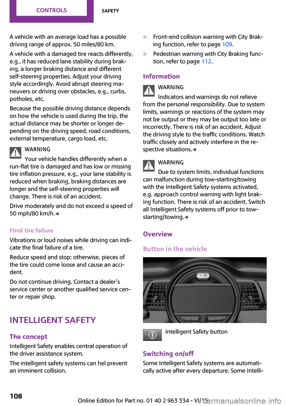
Button in the vehicle
Intelligent Safety button
Switching on/off Some Intelligent Safety systems are automati‐
cally active after every departure. Some Intelli‐
Seite 108CONTROLSSafety108
Online Edition for Part no. 01 40 2 963 334 - VI/15
Page 109 of 246

gent Safety systems activate according to the
last setting.
Press button briefly:▷The menu for the intelligent safety
system is displayed. The systems
are individually switched off ac‐
cording to their respective settings.▷LED lights up orange or goes out respective
to their individual settings.
Adjust as needed. Individual settings are stored
for the profile currently used.
Press button again:
▷All Intelligent Safety systems are
activated.▷The LED lights up green.
Hold down button:
▷All Intelligent Safety systems are
turned off.▷The LED goes out.
Front-end collision
warning with City Brak‐
ing function
The concept
The system can help prevent accidents. If an
accident cannot be prevented, the system will
help reduce the collision speed.
The system sounds a warning before an immi‐
nent collision and actuates brakes independ‐
ently if needed.
The automatic braking intervention is done
with limited force and duration.
The system is controlled via a camera in the
base of the mirror.
The front-end collision warning is available
even if cruise control has been deactivated.
With the vehicle approaching another vehicle
intentionally, the collision warning and braking
are delayed in order to avoid false system reac‐
tions.
General information The system warns at two levels of an imminent
danger of collision at speeds from approx.
3 mph/5 km/h. Time of warnings may vary with
the current driving situation.
Appropriate braking kicks in at speeds of up to
35 mph/60 km/h.
Detection range
It responds to objects if they are detected by
the system.
Information WARNING
Indicators and warnings do not relieve
from the personal responsibility. Due to system
limits, warnings or reactions of the system may
not be output or they may be output too late or
incorrectly. There is risk of an accident. Adjust
the driving style to the traffic conditions. Watch
traffic closely and actively interfere in the re‐
spective situations. ◀
WARNING
Due to system limits, individual functions
can malfunction during tow-starting/towing
with the Intelligent Safety systems activated,
e.g. approach control warning with light brak‐ ing function. There is risk of an accident. Switch
Seite 109SafetyCONTROLS109
Online Edition for Part no. 01 40 2 963 334 - VI/15
Page 110 of 246

all Intelligent Safety systems off prior to tow-
starting/towing. ◀
Overview
Button in the vehicle
Intelligent Safety button
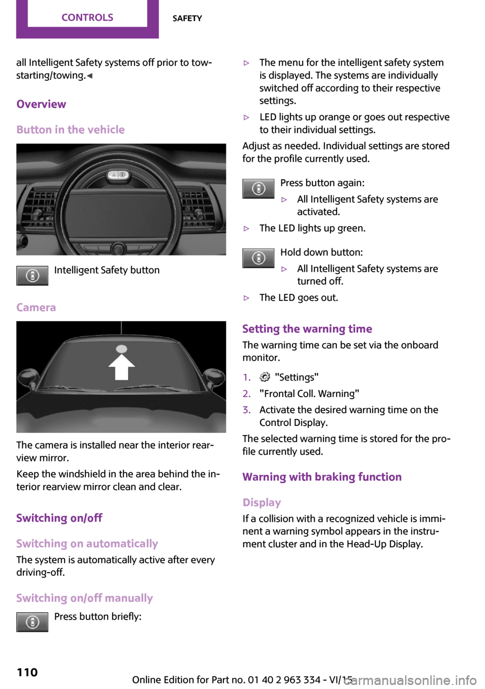
Camera
The camera is installed near the interior rear‐
view mirror.
Keep the windshield in the area behind the in‐
terior rearview mirror clean and clear.
Switching on/off
Switching on automatically
The system is automatically active after every
driving-off.
Switching on/off manually Press button briefly:
▷The menu for the intelligent safety system
is displayed. The systems are individually
switched off according to their respective
settings.▷LED lights up orange or goes out respective
to their individual settings.
Adjust as needed. Individual settings are stored
for the profile currently used.
Press button again:
▷All Intelligent Safety systems are
activated.▷The LED lights up green.
Hold down button:
▷All Intelligent Safety systems are
turned off.▷The LED goes out.
Setting the warning time
The warning time can be set via the onboard
monitor.
1. "Settings"2."Frontal Coll. Warning"3.Activate the desired warning time on the
Control Display.
The selected warning time is stored for the pro‐
file currently used.
Warning with braking function
Display
If a collision with a recognized vehicle is immi‐
nent a warning symbol appears in the instru‐
ment cluster and in the Head-Up Display.
Seite 110CONTROLSSafety110
Online Edition for Part no. 01 40 2 963 334 - VI/15
Page 112 of 246

Warning sensitivityThe more sensitive the warning settings are,
the more warnings are displayed. However,
there may also be an excess of false warnings.
Pedestrian warning with
city braking function
The concept
The system can help prevent accidents with pe‐
destrians.
The system issues a warning in the city driving
speed area if there is imminent danger of a col‐
lision with pedestrians and includes a braking
function.
A camera at the base of the rearview mirror
controls the system.
General information With sufficient brightness, the system warns
about possible collision danger with pedes‐
trians starting at approx. 6 mph/10 km/h to ap‐
prox. 35 mph/60 km/h and assists with braking
before a collision.
Under those circumstances it reacts to people
who are within the detection range of the sys‐ tem.
Detection range
The detection area in front of the vehicle is div‐
ided into two areas
▷Central area, arrow 1, directly in front of the
vehicle.▷Expanded area, arrow 2, to the right and
left.
A collision is imminent if pedestrians are lo‐
cated within the central area. A warning is is‐
sued about pedestrians who are located within
the extended area only if they are moving in
the direction of the central area.
Information WARNING
Indicators and warnings do not relieve
from the personal responsibility. Due to system
limits, warnings or reactions of the system may
not be output or they may be output too late or
incorrectly. There is risk of an accident. Adjust
the driving style to the traffic conditions. Watch
traffic closely and actively interfere in the re‐
spective situations. ◀
WARNING
Due to system limits, individual functions
can malfunction during tow-starting/towing
with the Intelligent Safety systems activated,
e.g. approach control warning with light brak‐
ing function. There is risk of an accident. Switch
all Intelligent Safety systems off prior to tow-
starting/towing. ◀
Overview
Button in the vehicle
Seite 112CONTROLSSafety112
Online Edition for Part no. 01 40 2 963 334 - VI/15
Page 162 of 246

LoadOn 3-door modelsOn 5-door models
The maximum load is the sum of the weight of
the occupants and the cargo.
The greater the weight of the occupants, the
less cargo that can be transported.
Stowing cargo
▷Cover sharp edges and corners on the
cargo.▷Heavy cargo: stow as far forward as possi‐
ble, directly behind and at the bottom of
the rear passenger seat backrests.▷Very heavy cargo: when the rear seat is not
occupied, secure each of the outer safety
belts in the opposite buckle.▷If necessary, fold down the rear backrests
to stow cargo.▷Do not stack cargo above the top edge of
the backrests.Securing cargo
Information WARNING
Improperly stowed objects can shift and
be thrown into the car's interior, e.g. in the
event of an accident or during braking and eva‐
sive maneuvers. Vehicle occupants can be hit
and injured. There is risk of injuries. Stow and
secure objects and cargo properly. ◀▷Smaller and lighter items: secure with re‐
taining straps or with draw straps.▷Larger and heavy objects: secure with
cargo straps.
Attach the cargo straps, retaining straps or
draw straps to the lashing eyes in the trunk.
Lashing eyes in the cargo area
Without storage compartment package: to se‐
cure the cargo there are two lashing eyes, ar‐
row 1, in the cargo area.
With storage compartment package: to secure
the cargo there are six lashing eyes, arrows 1
and 2, in the cargo area.
Roof-mounted luggage
rack
Information Installation only possible with roof rack.
Roof racks are available as special accessories.
Seite 162DRIVING TIPSLoading162
Online Edition for Part no. 01 40 2 963 334 - VI/15
Page 190 of 246

4.Slide the sealant container upright into the
holder on the compressor housing, ensur‐
ing that it engages audibly.5.Screw the connection hose onto the tire
valve of the nonworking wheel.6.With the compressor switched off, insert
the plug into a power socket inside the ve‐
hicle.7.With the ignition turned on or the engine
running, switch on the compressor.
Let the compressor run for approx. 3 to 8 mi‐
nutes to fill the tire with sealant and achieve a
tire inflation pressure of approx. 2.5 bar.
While the tire is being filled with sealant, the
tire inflation pressure may sporadically reach
approx. 5 bar. Do not switch off the compressor
at this point.
CAUTION
The compressor can overheat during ex‐
tended operation. There is risk of property
damage. Do not run the compressor for more
than 10 min. ◀
If a tire inflation pressure of 2 bar is not
reached:
1.Switch off the compressor.2.Unscrew the filling hose from the wheel.3.Drive forward and back to distribute the
sealant in the tire.4.Inflate the tire again using the compressor.
If a tire inflation pressure of 2 bar cannot be
reached, contact your dealer’s service cen‐
ter or another qualified service center or re‐
pair shop.
Stowing the Mobility System
1.Remove the connection hose of the sealant
container from the wheel.2.Remove the connection hose from the seal‐
ant container.Seite 190MOBILITYWheels and tires190
Online Edition for Part no. 01 40 2 963 334 - VI/15