2016 MERCEDES-BENZ SL ROADSTER charging
[x] Cancel search: chargingPage 8 of 333
Automatic headlamp mode
.............. 113
Automatic transmission
Accelerator pedal position ............ .144
Changing gear ............................... 144
Display message ............................ 239
Drive program displa y.................... 142
Drive programs .............................. 145
Driving tips .................................... 144
DYNAMIC SELECT button (all vehi-
cles except Mercedes-AMG vehi-
cles) ............................................... 139
DYNAMIC SELECT controller
(Mercedes-AMG vehicles) .............. 140
Emergency running mod e.............. 151
Engaging drive position .................. 143
Engaging neutral ............................ 143
Engaging park position automati-
cally ............................................... 143
Engaging reverse gear ................... 143
Engaging the park position ............ 142
Gearshift recommendation ............ 149
Kickdown ....................................... 145
Manual shifting .............................. 147
Oil temperature (on-board com-
puter, Mercedes-AMG vehicles) ..... 213
Overview ........................................ 141
Problem (fault) ............................... 151
Pulling away ................................... 134
Selector lever ................................ 141
Starting the engine ........................ 134
Steering wheel gearshift paddle s... 147
Transmission position display ........ 142
Transmission positions .................. 144
Automatic transmission emer-
gency running mode ......................... 151B
Back button ....................................... 254
BAS (Brake Assist System) ................. 62
Battery (key)
Checking .......................................... 80
Important safety notes .................... 79
Replacing ......................................... 80
Battery (vehicle)
Charging ........................................ 295
Display message ............................ 230
Important safety notes .................. 293 Jump starting ................................. 296
Overview ........................................ 293
Belt
see Seat belts
Belt tensioner
Activation ......................................... 51
Blind Spot Assist
see Active Blind Spot Assist
Bluetooth ®
Connecting another mobile
phone ............................................ 257
Searching for a mobile phone ........ 256
See also Digital Owner's Manua l... 253
Telephony ...................................... 256
Bonnet
Active bonnet (pedestrian protec-tion) ............................................... 276
Closing ........................................... 277
Display message ............................ 241
Important safety notes .................. 276
Opening ......................................... 277
Boot
Emergency release .......................... 89
Important safety notes .................... 85
Locking separately ........................... 89
Opening/closing (automatically
from inside) ...................................... 88
Opening/closing (automatically
from outside) ................................... 86
Opening/closing (from the out-
side, HANDS-FREE ACCESS) ............ 87
Opening/closing (manually from
outside) ............................................ 85
Overview .......................................... 85
Power closing .................................. 84
Boot lid
Display message ............................ 240
Opening dimensions ...................... 327
Boot load (maximum) ........................ 327
Boot separator
Display message ............................ 241
Fitting .............................................. 96
General notes .................................. 95
Opening/closing .............................. 95
Removing ......................................... 96
Bottle holders .................................... 267 Index
5
Page 21 of 333

SPORT handling mode
Deactivating/activating
(Mercedes-AMG vehicles) ................70
Warning lamp ................................. 248
Start/stop function
see ECO start/stop function
Starting (engine) ................................ 133
STEER CONTROL ..................................74
Steering
Display message ............................2 41
Steering Assist and Stop&Go Pilot
(DISTRONIC PLUS)
Activating/deactivating ................. 207
Steering assistant STEER CON-
TROL
see STEER CONTROL
Steering Pilot and Stop&Go Pilot
Display message ............................ 235
Steering wheel
Adjusting (electrically) ................... 106
Button overview ............................... 33
Buttons (on-board computer) ......... 200
Important safety notes .................. 106
Storing settings (memory func-
tion) ............................................... 111
Steering wheel gearshift paddles .... 147
Stopwatch (RACETIMER) ................... 213
Stowage areas ................................... 262
Stowage compartments
Armrest (under) ............................ .262
Centre console .............................. 263
Centre console (rear) ..................... 263
Cup holder ..................................... 266
Glove compartment ....................... 262
Important safety information ......... 262
Rear ............................................... 264
Spectacles compartment .............. .263
Stowage net ....................................... 264
Stowage space
Display message ............................ 241
Stowage net ................................... 264
Umbrella holder ............................ .263
Stowage well beneath the boot
floor .................................................... 266
Summer tyres ................................... .306
Sun visor ............................................ 267 Surround lighting (on-board com-
puter)
................................................. .210
Suspension settings
Active Body Control (ABC) (exceptMercedes-AMG vehicles) .............. .176
Active Body Control (ABC)
(Mercedes-AMG vehicles) .............. 179
SETUP (on-board computer) .......... 213
Switching on media mode
Via the device lis t.......................... 260 T
Tail lamps Display message ............................ 228
see Lights
Technical data
Capacities ...................................... 322
Emergency spare wheel ................. 318
Information .................................... 320
Tyres/wheels ................................. 317
Vehicle data ................................... 327
Telephone
Accepting a call (multifunction
steering wheel) .............................. 206
Authorising a mobile phone (con-
necting) ......................................... 256
Connecting a Mobile phone (gen-
eral information) ............................ 256
Display message ............................ 241
Menu (on-board computer) ............ 205
Number from the phone book ........ 206
Redialling ....................................... 206
Rejecting/ending a call ................. 206
See also Digital Owner's Manua l... 253
Switching between mobile
phones ........................................... 257
Telephone compartment ................ 262
Telephone module with Bluetooth ®
(SAP profile) Activating and connecting the
module ........................................... 258
Charging a mobile phone ............... 260
Connecting the mobile phone ........ 259
Connecting the module using a
USB cable ...................................... 258
Data modem mode ........................ 259
Installing the module ..................... 258 18
Index
Page 121 of 333
Interior lighting control
General notes In order to prevent the vehicle's battery from
discharging, the interior lighting functions are
automatically deactivated after some time,
unless the key is in position 2in the ignition lock.
The colour and brightness of the ambient light-
ing are set using the multimedia system
(Y page 210).
Automatic interior lighting control X
To switch on: set the switch to centre posi-
tion A.
X To switch off: set the switch to the |
position.
The interior lighting automatically switches on if you:
R unlock the vehicle
R open a door
R remove the key from the ignition lock
The interior lighting is activated for a short time
when the key is removed from the ignition lock.
You can activate this delayed switch-off using
the on-board computer (Y page 211).Replacing bulbs
The front and rear lamps of your vehicle are
equipped with LED bulbs. Do not replace the
bulbs yourself. Contact a qualified specialist
workshop, which has the necessary specialist
knowledge and tools to carry out the work
required.
Bulbs and lamps are an important aspect of
vehicle safety. You must therefore make sure
that these function correctly at all times. Have
the headlamp setting checked regularly. Windscreen wipers
Switching the windscreen wipers on/
off
! Do not operate the windscreen wipers when
the windscreen is dry, as this could damage
the wiper blades. Moreover, dust that has col- lected on the windscreen can scratch the glass if wiping takes place when the wind-
screen is dry.
If it is necessary to switch on the windscreen
wipers in dry weather conditions, always
operate them using washer fluid.
! If the windscreen wipers leave smears on
the windscreen after the vehicle has been
washed in an automatic car wash, this may be
due to wax or other residue. Clean the wind-
screen with washer fluid after an automatic
car wash.
! Intermittent wiping with rain sensor: due to
optical influences and the windscreen becom- ing dirty in dry weather conditions, the wind-
screen wipers may be activated inadvertently.
This could damage the windscreen wiper
blades or scratch the windscreen.
For this reason, you should always switch off
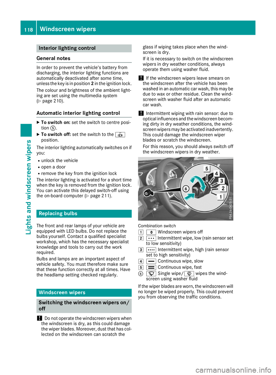
the windscreen wipers in dry weather. Combination switch
1 $ Windscreen wipers off
2 Ä Intermittent wipe, low (rain sensor set
to low sensitivity)
3 Å Intermittent wipe, high (rain sensor
set to high sensitivity)
4 ° Continuous wipe, slow
5 ¯ Continuous wipe, fast
B í Single wipe/ îwipes the wind-
screen using washer fluid
If the wiper blades are worn, the windscreen will no longer be wiped properly. This could prevent
you from observing the traffic conditions. 118
Windscreen wipersLights and windscreen wipers
Page 158 of 333
Applying automatically
The electric parking brake is automatically
applied when the transmission is in position P
and:
R the engine is switched off or
R the driver is not wearing a seat belt and the
driver's door is opened
To prevent the electric parking brake from being automatically applied, pull handle :.
The electric parking brake is also applied auto-
matically if:
R Distance Pilot DISTRONIC brings the vehicle
to a standstill or
R the HOLD function is keeping the vehicle sta-
tionary
In addition, at least one of the following condi-
tions must be fulfilled:
R the engine is switched off
R the driver is not wearing a seat belt and the
driver's door is opened
R there is a system malfunction
R the power supply is insufficient
R the vehicle is stationary for a lengthy period
The red !indicator lamp in the instrument
cluster lights up.
The electric parking brake is not automatically
applied if the engine is switched off by the ECO start/stop function.
Releasing automatically The electric parking brake is released automat-
ically when all of the following conditions are
fulfilled:
R the engine is running
R the transmission is in position Dor R
R the driver's seat belt is fastened
R you depress the accelerator pedal
If the transmission is in position R, the boot lid
must be closed.
If your seat belt is not fastened, the following
conditions must be fulfilled to automatically
release the electric parking brake:
R the driver's door is closed
R you have shifted out of Por you have previ-
ously driven faster than 3 km/h
Ensure that you do not depress the accelerator
pedal unintentionally. Otherwise, the parking brake will be released and the vehicle will start
to move.
Emergency braking The vehicle can also be braked during an emer-
gency by using the electric parking brake.
X While driving, push handle :of the electric
parking brake.
The vehicle is braked for as long as the handle of the electric parking brake is pressed. The
longer the electric parking brake handle is
depressed, the greater the braking force.
During braking:
R a warning tone sounds
R the Release parking brake
Release parking brake message
appears
R the red !indicator lamp in the instrument
cluster flashes
When the vehicle has been braked to a stand-
still, the electric parking brake is applied. Parking up the vehicle
If you leave the vehicle parked up for longer than
four weeks, the battery may be damaged by
exhaustive discharging.
If you leave the vehicle parked up for longer than
six weeks, it may suffer from lack of use.
X Contact a qualified specialist workshop and
seek advice.
i You can obtain information about trickle
chargers from a qualified specialist work-
shop. Driving tips
General notes
Important safety notes G
WARNING
If you switch off the ignition while driving,
safety-relevant functions are only available
with limitations, or not at all. This could affect, for example, the power steering and the brake
boosting effect. You will require considerably Driving tips
155Driving and pa rking
Z
Page 261 of 333
R
access to the phone book of the mobile phone
(if supported by the mobile phone)
(Y page 259)
R charging a mobile phone via the USB connec-
tion (Y page 260)
i The module is not available in all vehicles,
depending on the equipment.
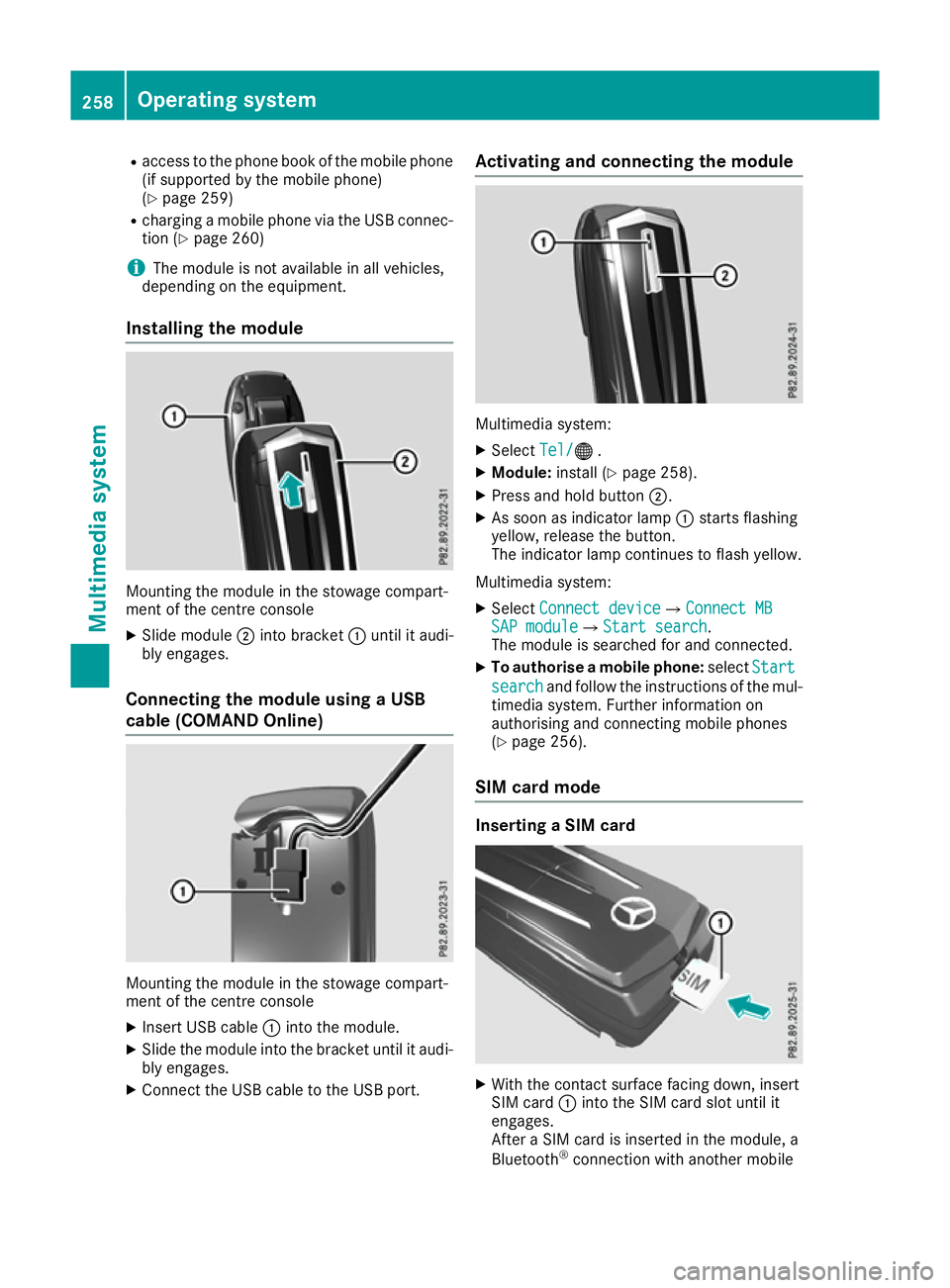
Installing the module Mounting the module in the stowage compart-
ment of the centre console
X Slide module ;into bracket :until it audi-
bly engages.
Connecting the module using a USB
cable (COMAND Online) Mounting the module in the stowage compart-
ment of the centre console
X Insert USB cable :into the module.
X Slide the module into the bracket until it audi-
bly engages.
X Connect the USB cable to the USB port. Activating and connecting the module
Multimedia system:
X Select Tel/ Tel/® .
X Module: install (Y page 258).
X Press and hold button ;.
X As soon as indicator lamp :starts flashing
yellow, release the button.
The indicator lamp continues to flash yellow.
Multimedia system: X Select Connect device Connect device QConnect MBConnect MB
SAP module
SAP module QStart searchStart search .
The module is searched for and connected.
X To authorise a mobile phone: selectStart
Start
search
search and follow the instructions of the mul-
timedia system. Further information on
authorising and connecting mobile phones
(Y page 256).
SIM card mode Inserting a SIM card
X
With the contact surface facing down, insert
SIM card :into the SIM card slot until it
engages.
After a SIM card is inserted in the module, a
Bluetooth ®
connection with another mobile 258
Operating systemMultimedia system
Page 263 of 333
Text messages
Requirements
The module is connected with the mobile phone
(Y page 259) or is being used in the SIM card
mode (Y page 258).
Activating/deactivating text message
downloading from the mobile phone Dial number Function
00080 Text message down-
loading is deactiva-
ted.
00081 Text message down-
loading is activated.
For further information on receiving text mes-
sages when using the telephone module (see
the manufacturer's operating instructions).
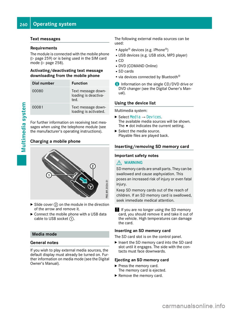
Charging a mobile phone X
Slide cover ;on the module in the direction
of the arrow and remove it.
X Connect the mobile phone with a USB data
cable to USB socket :.Media mode
General notes If you wish to play external media sources, the
default display must already be turned on. Fur-
ther information on media mode (see the Digital
Owner's Manual). The following external media sources can be
used:
R Apple ®
devices (e.g. iPhone ®
)
R USB devices (e.g. USB stick, MP3 player)
R CD
R DVD (COMAND Online)
R SD cards
R via devices connected by Bluetooth ®
i Information on the single CD/DVD drive or
DVD changer (see the Digital Owner's Man-
ual).
Using the device list Multimedia system:
X Select Media MediaQ Devices
Devices.
The available media sources will be shown.
The #dot indicates the current setting.
X Select the media source.
Playable files are played back.
Inserting/removing SD memory card Important safety notes
G
WARNING
SD memory cards are small parts. They can be swallowed and cause asphyxiation. This
poses an increased risk of injury or even fatal injury.
Keep SD memory cards out of the reach of
children. If an SD memory card is swallowed,
seek immediate medical attention.
! If you are no longer using the SD memory
card, you should remove it and take it out of
the vehicle. High temperatures can damage
the card.
Inserting an SD memory card
The SD card slot is on the control panel.
X Insert the SD memory card into the SD card
slot until it engages. The side with the con-
tacts must face downwards.
Ejecting an SD memory card X Press the memory card.
The memory card is ejected.
X Remove the memory card. 260
Operating systemMultimedia system
Page 296 of 333

X
To reduce the tyre pressure: depress pres-
sure release button Enext to pressure gauge
F.
X When the tyre pressure is correct, unscrew
the filler hose from the valve of the sealed
tyre.
X Screw the valve cap onto the tyre valve of the
sealed tyre.
X Pull the tyre sealant bottle out of the tyre
inflation compressor.
The filler hose stays on the tyre sealant bottle.
X Drive to the nearest qualified specialist work-
shop and have the tyre changed there.
X Have the tyre sealant bottle replaced as soon
as possible at a qualified specialist workshop.
X Have the tyre sealant bottle replaced every
four years at a qualified specialist workshop. Battery (vehicle)
Important safety notes
Work on the battery, e.g. removing or fitting,
requires specialist knowledge and the use of
special tools. Therefore, always have work on
the battery carried out at a qualified specialist
workshop. G
WARNING
Work carried out incorrectly on the battery
can lead, for example, to a short circuit and
thus damage the vehicle electronics. This can lead to function restrictions applying to
safety-relevant systems, e.g the lighting sys-
tem, the ABS (anti-lock braking system) or the
ESP ®
(Electronic Stability Program). The oper-
ating safety of your vehicle may be restricted.
You could lose control of the vehicle, for
example:
R when braking
R in the event of abrupt steering manoeuvres
and/or when the vehicle's speed is not
adapted to the road conditions
There is a risk of an accident.
In the event of a short circuit or a similar inci- dent, contact a qualified specialist workshop
immediately. Do not drive any further. Always have work on the battery carried out at a
qualified specialist workshop.
Further information about ABS (Y page 62) and
ESP ®
(Y page 67). G
WARNING
Electrostatic build-up can lead to the creation of sparks, which could ignite the highly explo-
sive gases of a battery. There is a risk of an
explosion.
Before handling the battery, touch the vehicle body to remove any existing electrostatic
build-up.
The highly flammable gas mixture is created
while the battery is charging and when jump-
starting.
Always make sure that neither you nor the bat-
tery is electrostatically charged. Electrostatic
charge is created, for example: R by wearing synthetic fibre clothing
R by friction between clothing and the seat
R when you pull or push the battery across car-
pet or other synthetic materials
R when you rub the battery with a cloth G
WARNING
During the charging process, a battery produ- ces hydrogen gas. If a short circuit occurs or
sparks are created, the hydrogen gas can
ignite. There is a risk of an explosion.
R Make sure that the positive terminal of a
connected battery does not come into con-
tact with vehicle parts.
R Never place metal objects or tools on a bat-
tery.
R It is important that you observe the descri-
bed order of the battery terminals when
connecting and disconnecting a battery.
R When jump-starting, make sure that the
battery poles with identical polarity are
connected.
R It is particularly important to observe the
described order when connecting and dis-
connecting the jump leads.
R Never connect or disconnect the battery
terminals while the engine is running. Battery (vehicle)
293Breakdown assis tance Z
Page 298 of 333
vehicle will then use very little energy, thus con-
serving battery power. Charging the battery
G
WARNING
During charging and jump-starting, explosive
gases can escape from the battery. There is a risk of an explosion.
Particularly avoid fire, naked flames, creating
sparks and smoking. Ensure there is sufficient
ventilation while charging and jump-starting.
Do not lean over a battery. G
WARNING
Battery acid is caustic. There is a risk of injury. Avoid contact with the skin, eyes or clothing.
Do not breathe in any battery gases. Do not
lean over the battery. Keep the batteries out
of the reach of children. Immediately rinse off
battery acid thoroughly with plenty of clean
water and seek medical attention at once. G
WARNING
A discharged battery can freeze at tempera-
tures below freezing point. When jump-start-
ing the vehicle or charging the battery, gases can escape from the battery. There is a risk of
an explosion.
Allow the frozen battery to thaw out before
charging it or jump-starting.
! Only charge the installed battery with a bat-
tery charger which has been tested and
approved by Mercedes-Benz. These battery
chargers allow the battery to be charged while still installed in the vehicle.
! Only use battery chargers with a maximum
charging voltage of 14.8 V.
! Only
charge the battery using the jump-start
connection point.
The jump-starting connection point is in the
engine compartment.
If the indicator/warning lamps do not light up at
low temperatures, it is very likely that the dis-
charged battery has frozen. In this case you may
neither jump-start the vehicle nor charge the battery. The service life of a battery that has
been thawed may be reduced. The starting char-
acteristics may be impaired, especially at low
temperatures. Have the thawed battery
checked at a qualified specialist workshop.
Read the battery charger's operating instruc-
tions before charging the battery.
X Open the bonnet.
X Connect the battery charger to the positive
terminal and earth point in the same order as
when connecting the donor battery in the
jump-starting procedure (Y page 296). Battery (vehicle)
295Breakdown assistance Z