2016 MERCEDES-BENZ S-Class SEDAN service indicator
[x] Cancel search: service indicatorPage 350 of 438
door opener, contact an authorized Mercedes-
Benz Center.
Alternatively, you can call the following tele-
phone assistance services:
RUSA:Mercedes-Benz Customer Assistance
Center at 1-800-FOR-MERCedes
RCanada: Customer Service at
1-800-387-0100
RHomeLink®hotline 1-800-355-3515 (free of
charge)
More information on HomeLink
®and/or com-
patible products is also available online at
http://www.homelink.co m.
Notes on the declaration of conformity
(
Ypage 28).
USA: FCC ID: CB2HMIHL4
Canada: IC: 279B-HMIHL4
Important safety notes
GWARNING
When you operate or program the garage door
with the integrated garage door opener, per-
sons in the range of movement of the garage
door can become trapped or struck by the
garage door. There is a risk of injury.
When using the integrated garage door
opener, always make sure that nobody is
within the range of movement of the garage
door.
GWARNING
Combustion engines emit poisonous exhaust
gases such as carbon monoxide. Inhaling
these exhaust gases leads to poisoning. There
is a risk of fatal injury. Therefore never leave
the engine running in enclosed spaces with-
out sufficient ventilation.
Programming
Programming buttons
Pay attention to the "Important safety notes"
(Ypage 348).
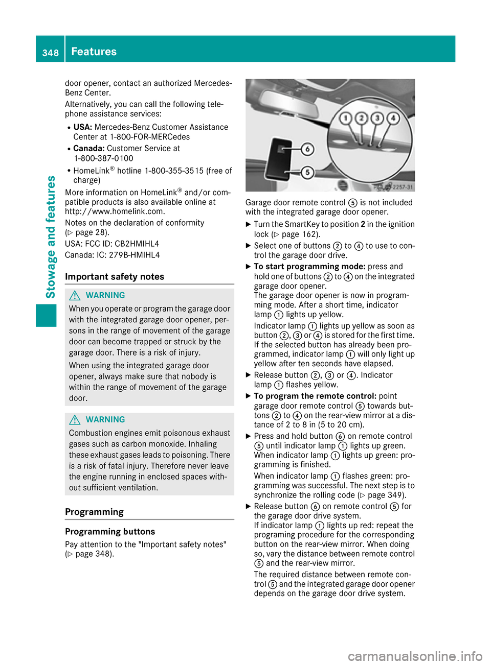
Garage door remote control Ais not included
with the integrated garage door opener.
XTurn the SmartKey to position 2in the ignition
lock (Ypage 162).
XSelect one of buttons ;to? to use to con-
trol the garage door drive.
XTo start programming mode: press and
hold one of buttons ;to? on the integrated
garage door opener.
The garage door opener is now in program-
ming mode. After a short time, indicator
lamp :lights up yellow.
Indicator lamp :lights up yellow as soon as
button ;,=or? is stored for the first time.
If the selected button has already been pro-
grammed, indicator lamp :will only light up
yellow after ten seconds have elapsed.
XRelease button ;,=or?. Indicator
lamp :flashes yellow.
XTo program the remote control: point
garage door remote control Atowards but-
tons ;to? on the rear-view mirror at a dis-
tance of 2 to 8 in (5 to 20 cm).
XPress and hold button Bon remote control
A until indicator lamp :lights up green.
When indicator lamp :lights up green: pro-
gramming is finished.
When indicator lamp :flashes green: pro-
gramming was successful. The next step is to synchronize the rolling code (
Ypage 349).
XRelease button Bon remote control Afor
the garage door drive system.
If indicator lamp :lights up red: repeat the
programing procedure for the corresponding
button on the rear-view mirror. When doing
so, vary the distance between remote control
A and the rear-view mirror.
The required distance between remote con-
trol Aand the integrated garage door opener
depends on the garage door drive system.
348Features
Stowage and features
Page 377 of 438
ing the vehicle or charging the battery, gasescan escape from the battery. There is a risk of
an explosion.
Allow the frozen battery to thaw out before
charging it or jump-starting.
!Only use battery chargers with a maximum
charging voltage of 14.8 V.
All vehicles:
!Only charge the battery using the jump-
starting connection point.
The jump-starting connection point is in the
engine compartment (
Ypage 376).
XOpen the hood.
XConnect the battery charger to the positive
terminal and ground point in the same order
as when connecting the donor battery in the
jump-starting procedure (
Ypage 376).
Keep away from fire and open flames. Do not
lean over a battery. Never charge the battery if it
is still installed in the vehicle, unless you use a
battery charger which has been tested and
approved by Mercedes-Benz. A battery charger
unit specially adapted for Mercedes-Benz vehi-
cles and tested and approved by Mercedes-
Benz is available as an accessory. It permits the
charging of the battery in its installed position.
Contact an authorized Mercedes-Benz Center
for further information and availability. Read the
battery charger's operating instructions before
charging the battery.
All vehicles except Mercedes-AMG vehicles:
if the indicator/warning lamps in the instrument
cluster do not light up at low temperatures, it is
very likely that the discharged battery has fro-
zen. In this case you may neither jump-start the
vehicle nor charge the battery. The service life of
a thawed-out battery may be shorter. The start-
ing characteristics can be impaired, particularly
at low temperatures. Have the thawed- out bat
-
tery checked at a qualified specialist workshop.
Mercedes-AMG vehicles: at low temperatures,
do not charge a battery which has been removed
using a battery charger. Allow the battery to
warm up gently first, if necessary. Otherwise,
the service life can be shortened and the start-
ing characteristics impaired, especially at low
temperatures.
PLUG-IN HYBRID vehicles: if the battery
charge is sufficient, the high-voltage battery can
also supply the 12 V battery. This only happens if the condition of charge of the 12 V battery
requires this, e.g. after using electrical consum-
ers for an extended period with the engine
switched off. As the on-board voltage is contin-
uously monitored this can also be performed
when the engine is switched off. The condition of
charge of the 12 V battery and the on-board
voltage are thereby kept stable for a longer
period.
Battery (vehicle)375
Breakdown assistance
Z
Page 378 of 438
Jump-starting
For the jump-starting procedure, use only the jump-starting connection point in the engine com-
partment, consisting of a positive terminal and a ground point.
All vehicles except Mercedes-AMG vehicles:
GWARNING
Battery acid is caustic. There is a risk of injury.
Avoid contact with skin, eyes or clothing. Do not inhale any battery gases. Do not lean over the
battery. Keep children away from batteries. Wash away battery acid immediately with plenty of
clean water and seek medical attention.
GWARNING
During charging and jump-starting, explosive gases can escape from the battery. There is a risk of an explosion.
Particularly avoid fire, open flames, creating sparks and smoking. Ensure there is sufficient ven-
tilation while charging and jump-starting. Do not lean over a battery.
GWARNING
During the charging process, a battery produces hydrogen gas. If a short circuit occurs or sparks
are created, the hydrogen gas can ignite. There is a risk of an explosion.
RMake sure that the positive terminal of a connected battery does not come into contact with
vehicle parts.
RNever place metal objects or tools on a battery.
RIt is important that you observe the described order of the battery terminals when connecting
and disconnecting a battery.
RWhen jump-starting, make sure that the battery poles with identical polarity are connected.
RIt is particularly important to observe the described order when connecting and disconnecting
the jumper cables.
RNever connect or disconnect the battery terminals while the engine is running.
GWARNING
A discharged battery can freeze at temperatures below freezing point. When jump-starting the
vehicle or charging the battery, gases can escape from the battery. There is a risk of an explosion. Allow the frozen battery to thaw out before charging it or jump-starting.
If, at low temperatures, the indicator lamps/warning lamps in the instrument cluster do not light up,
it is highly likely that the discharged battery has frozen. In this case, you may neither charge the
battery nor jump-start the vehicle. The service life of a thawed-out battery may be shorter. The
starting characteristics can be impaired, particularly at low temperatures. Have the thawed-out
battery checked at a qualified specialist workshop.
All vehicles:
!Avoid repeated and lengthy starting attempts. Otherwise, the catalytic converter could be
damaged by the non-combusted fuel.
376Jump-starting
Breakdown assistance
Page 387 of 438
Regular checking of wheels and tires
GWARNING
Damaged tires can cause tire inflation pres-
sure loss. As a result, you could lose control of
your vehicle. There is a risk of accident.
Check the tires regularly for signs of damage
and replace any damaged tires immediately.
Check wheels and tires for damage at least once
a month. Check wheels and tires after driving
off-road or on rough roads. Damaged wheels
can cause a loss of tire pressure. Pay particular
attention to damage such as:
Rcuts in the tires
Rpunctures
Rtears in the tires
Rbulges on tires
Rdeformation or severe corrosion on wheels
Regularly check the tire tread depth and the
condition of the tread across the whole width of
the tire (
Ypage 385). If necessary, turn the
front wheels to full lock in order to inspect the
inner side of the tire surface.
All wheels must have a valve cap to protect the
valve against dirt and moisture. Do not mount
anything onto the valve other than the standard
valve cap or other valve caps approved by
Mercedes-Benz for your vehicle. Do not use any
other valve caps or systems, e.g. tire pressure
monitoring systems.
Regularly check the pressure of all the tires par-
ticularly prior to long trips. Adjust the tire pres-
sure as necessary (
Ypage 387).
The service life of tires depe
nds, among other
things, on the following factors:
Rdriving style
Rtire pressure
Rdistance covered
Notes on tire tread
GWARNING
Insufficient tire tread will reduce tire traction.
The tire is no longer able to dissipate water.
This means that on wet road surfaces, the risk
of hydroplaning increases, in particular where
speed is not adapted to suit the driving con-
ditions. There is a risk of accident.
If the tire pressure is too high or too low, tires may exhibit different levels of wear at differ-
ent locations on the tire tread. Thus, you
should regularly check the tread depth and
the condition of the tread across the entire
width of all tires.
Minimum tire tread depth for:
RSummer tires: âin (3 mm)
RM+S tires: ãin (4 mm)
For safety reasons, replace the tires before
the legally prescribed limit for the minimum
tire tread depth is reached.
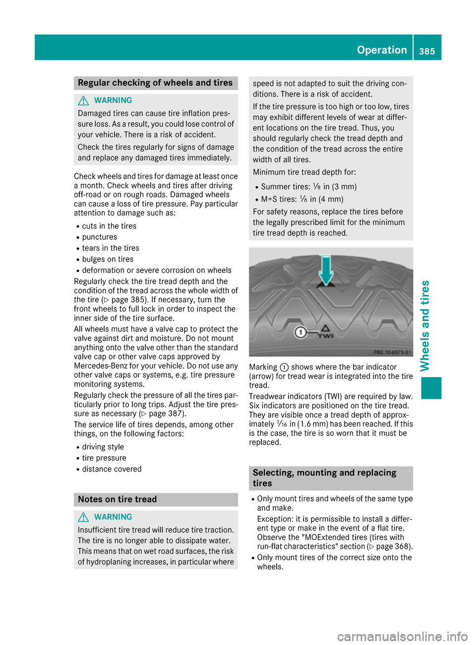
Marking :shows where the bar indicator
(arrow) for tread wear is integrated into the tire
tread.
Treadwear indicators (TWI) are required by law. Six indicators are positioned on the tire tread.
They are visible once a tread depth of approx-
imately áin (1.6 mm) has been reached. If this
is the case, the tire is so worn that it must be
replaced.
Selecting, mounting and replacing
tires
ROnly mount tires and wheels of the same type
and make.
Exception: it is permissible to install a differ-
ent type or make in the event of a flat tire.
Observe the "MOExtended tires (tires with
run-flat characteristics" section (
Ypage 368).
ROnly mount tires of the correct size onto the
wheels.
Operation385
Wheels and tires
Z
Page 395 of 438
XMake sure that the SmartKey is in position2
in the ignition lock.
XUse ò on the steering wheel to call up the
list of menus.
XPress 9or: on the steering wheel to
select the Servicemenu.
XPress theabutton.
XPress 9or: to select Tire Pres‐sure.
XPress the abutton.
The current tire pressure for each wheel or
the Tire pressure will be displayed
after driving a few minutesmessage
will be displayed in the multifunction display.
XPress the :button.
The UseCurrentPressuresasNewRef‐erenceValuesmessage appears in the mul-
tifunction display.
If you wish to confirm the restart:
XPress the abutton.
The TirePress.MonitorRestartedmes-
sage appears in the multifunction display.
After driving for a few minutes, the system
checks whether the current tire pressures are
within the specified range. The new tire pres-
sures are then accepted as reference values
and monitored.
If you wish to cancel the restart:
XPress the %button.
The tire pressure values stored at the last
restart will continue to be monitored.
Radio type approval for the tire pres-
sure monitor
CountryRadio type approval number
USAFCC ID: MRXMW2433A
FCC ID: MRXGG4
FCC ID: MRXMC34MA4
CanadaIC: 2546A-MW2433A
IC: 2546A-GG4
IC: 2546A-MC34MA4
Tire pressure loss warning system
(Canada only)
General notes
While the vehicle is in motion, the tire pressure
loss warning system monitors the set tire pres-
sure using the rotational speed of the wheels.
This enables the system to detect significant
pressure loss in a tire. If the speed of rotation of
a wheel changes as a result of a loss of pressure,
a corresponding warning message will appear in
the multifunction display.
You can recognize the tire pressure loss warning
by the Run Flat Indicator Active
Press'OK' to Restartmessage which appears in
the Servicemenu of the multifunction display.
Information on the message display can be
found in the "Restarting the tire pressure loss
warning system" section (
Ypage 394).
Important safety notes
The tire pressure warning system does not warn you of an incorrectly set tire pressure. Observe
the notes on the recommended tire pressure
(
Ypage 387).
The tire pressure loss warning does not replace
the need to regularly check the tire pressure. An
even loss of pressure on several tires at the
same time cannot be detected by the tire pres-
sure loss warning system.
The tire pressure monitor is not able to warn you
of a sudden loss of pressure, e.g. if the tire is
penetrated by a foreign object. In the event of a
sudden loss of pressure, bring the vehicle to a
halt by braking carefully. Avoid abrupt steering
movements.
The function of the tire pressure loss warning
system is limited or delayed if:
Rsnow chains are mounted on your vehicle's
tires.
Rroad conditions are wintry.
Ryou are driving on sand or gravel.
Ryou adopt a very sporty driving style (corner-
ing at high speeds or driving with high rates of acceleration).
Ryou are driving with a heavy load (in the vehi-
cle or on the roof).
Tire pressure393
Wheels and tires
Z
Page 396 of 438
Restarting the tire pressure loss warn-
ing system
Restart the tire pressure loss warning system if
you have:
Rchanged the tire pressure
Rchanged the wheels or tires
Rmounted new wheels or tires
XBefore restarting, make sure that the tire
pressures are set properly on all four tires for
the respective operating conditions.
The recommended tire pressure can be foundon the Tire and Loading Information placard
on the B-pillar on the driver's side. Addition-
ally, a tire pressure table is attached to the
fuel filler flap. The tire pressure loss warning
system can only give reliable warnings if you
have set the correct tire pressure. If an incor-
rect tire pressure is set, these incorrect val-
ues will be monitored.
XAlso observe the notes in the section on tire
pressures (Ypage 387).
XMake sure that the SmartKey is in position 2
in the ignition lock (Ypage 162).
XUse ò on the steering wheel to call up the
list of menus.
XPress 9or: on the steering wheel to
select the Servicemenu.
XPress theabutton.
XPress 9or: to select Tire Pres‐sure.
XPress the abutton.
The Run Flat Indicator ActivePress
'OK' to Restartmessage appears in the
multifunction display.
If you wish to confirm the restart:
XPress the abutton.
The Tire Pressure Now OK?message
appears in the multifunction display.
XPress 9or: to select Yes.
XPress the abutton.
The Run Flat Indicator Restartedmes-
sage appears in the multifunction display.
After a teach-in period, the tire pressure loss
warning system will monitor the set tire pres- sures of all four tires. If you wish to cancel the restart:
XPress the
%button.
or
XIf the Tire Pressure Now OK?message
appears, select Cancelby pressing9
or :.
XPress the abutton.
The tire pressure values stored at the last
restart will continue to be monitored.
Loading the vehicle
Instruction labels for tires and loads
GWARNING
Overloaded tires can overheat, causing a
blowout. Overloaded tires can also impair the steering and driving characteristics and lead
to brake failure. There is a risk of accident.
Observe the load rating of the tires. The load
rating must be at least half of the GAWR of
your vehicle. Never overload the tires by
exceeding the maximum load.
Two instruction labels on your vehicle show the maximum possible load.
(1) The Tire and Loading Information placard is on the B-pillar on the driver's side. The Tire
and Loading Information placard shows the
maximum permissible number of occu-
pants and the maximum permissible vehicle
load. It also contains details of the tire sizes
and corresponding pressures for tires
mounted at the factory.
(2) The vehicle identification plate is on the B- pillar on the driver's side. The vehicle iden-
tification plate informs you of the gross
vehicle weight rating. It is made up of the
vehicle weight, all vehicle occupants, the
fuel and the cargo. You can also find infor-
mation about the maximum gross axle
weight rating on the front and rear axle.
The maximum gross axle weight rating is
the maximum weight that can be carried by
one axle (front or rear axle). Never exceed
the maximum load or the maxi mum g
ross
axle weight rating for the front or rear axle.
394Loading the vehicle
Wheels and tires