2016 MERCEDES-BENZ GLE sport mode
[x] Cancel search: sport modePage 6 of 450
Alarm system
see ATA (Anti-Theft Alarm system)
AMG
Adaptive sport suspension sys-
tem ................................................ 209
AMG menu (on-board computer) .... .2 77
Anti-lock braking system
see ABS (Anti-lock Braking System)
Anti-Theft Alarm system
see ATA (Anti-Theft Alarm system)
Approach/departure angle .............. 190
Ashtray ............................................... 341
Assistance display (on-board com-
puter) ................................................. .2 71
Assistance menu (on-board com-
puter) ................................................. .2 71
ASSYST PLUS
Displaying a service message ....... .3 60
Hiding a service message .............. 360
Resetting the service interval dis-
play ................................................ 360
Service message ............................ 360
Special service requirements ......... 361
ATA (Anti-Theft Alarm system)
Activating/deactivating ................... 77
Function .......................................... .7 7
Switching off the alarm .................... 77
ATTENTION ASSIST
Activating/deactivating ................. 272
Display message ............................ 301
Function/notes ............................. 224
Audio menu (on-board computer) .... 269
Audio system
see separate operating instructions
Authorized Mercedes-Benz Center
see Qualified specialist workshop
Authorized workshop
see Qualified specialist workshop
AUTO lights
Display message ............................ 294
see Lights
Automatic car wash (care) ............... 361
Automatic engine start (ECO start/
stop function) .................................... 150
Automatic engine switch-off (ECO
start/stop function) .......................... 150
Automatic headlamp mode .............. 114 Automatic transmission
Accelerato r pedal position ............. 157
C hanging gear ............................... 157
DIRECT SELECT lever ..................... 154
Display message ............................ 311
Drive program ................................ 158
Drive program display .................... 154
Driving tips .................................... 157
DYNAMIC SELECT controller ......... 152
Emergency running mode .............. 162
Engaging drive position .................. 156
Engaging neutral ............................ 155
Engaging park position automati-
cally ............................................... 155
Engaging reverse gear ................... 155
Engaging the park position ............ 155
Gliding mode ................................. 157
Kickdown ....................................... 157
Manual shifting .............................. 159
Oil temperature (on-board com-
puter, Mercedes-AMG vehicles) ..... 277
Overview ........................................ 154
Problem (malfunction) ................... 162
Pulling away ................................... 148
Starting the engine ........................ 147
Steering wheel paddle shifters ...... 159
Trailer towing ................................. 158
Transmission position display ........ 154
Transmission positions .................. 156
Automatic transmission emer-
gency mode ....................................... 162
Axle load, permissible (trailer tow-
ing) ...................................................... 445
B
Bag hook ............................................ 334
Ball coupling
Installing ........................................ 258
Removing ....................................... 262
BAS (Brake Assist System) ................. 67
BAS PLUS with Cross-Traffic Assist
(Brake Assist PLUS with Cross-
Traffic Assist)
Function/notes ................................ 67
Important safety notes .................... 67
Battery (high-voltage)
see High-voltage battery4
Index
Page 22 of 450
Summer tires .................................... .3 89
Sun visor ............................................ 340
Suspension setting
AMG adaptive sport suspension
system .......................................... .2 09
Suspension settings
SETUP (on-board computer) .......... 277
SUV
(Sport Utility Vehicle) ....................... 28
Switching air-recirculation mode
on/off ................................................. 138
TTachometer ........................................ 263
Tail lamps
Display message ............................ 293
Tailgate
Display message ............................ 312
Emergency unlocking ....................... 90
Important safety notes .................... 87
Limiting the opening angle .............. .9 0
Opening dimensions ..................... .4 41
Opening/closing (automatically
from inside) ...................................... 89
Opening/closing (automatically
from outside) ................................... 88
Opening/closing (from outside) ....... 88
Power closing .................................. 86
Tank
see Fuel tank
Tank content
Fuel gauge ....................................... 34
Technical data
Capacities ...................................... 433
Emergency spare wheel ................. 430
Information ................................... .4 31
Tires/wheels ................................. 413
Trailer loads ................................... 445
Vehicle data ................................... 441
Telephone
Accepting a call (multifunction
steering wheel) .............................. 270
Display message ............................ 314
Menu (on-board computer) ............ 270
Number from the phone book ....... .2 70
Redialing ........................................ 271
Rejecting/ending a call ................. 270 Temperature
Coolant (display in the instrument
cluster) .......................................... 264
Coolant (on-board computer,
Mercedes-AMG vehicles) .............. .2 77
Coolant (on-board computer) ......... 273
Engine oil (on-board computer,
Mercedes-AMG vehicles) .............. .2 77
Outside temperature ..................... .2 64
Setting (climate control) ................ 134
Transmission oil (on-board com-
puter, Mercedes-AMG vehicles) ..... 277
Through-loading feature ................... 332
Time
see separate operating instructions
Timing (RACETIMER) ......................... 277
Tire pressure
Calling up (on-board computer) ..... 394
Checking manually ........................ 393
Displ ay message ............................ 309
Ma xi
mum ....................................... 393
Not reached (TIREFIT) .................... 373
Notes ............................................. 392
Reached (TIREFIT) .......................... 373
Recommended ............................... 390
Tire pressure loss warning system
General notes ................................ 393
Important safety notes .................. 394
Restarting ...................................... 394
Tire pressure monitor
Checking the tire pressure elec-
tronically ........................................ 396
Function/notes ............................ .3 94
General notes ................................ 394
Important safety notes .................. 395
Radio type approval for the tire
pressure monitor ........................... 397
Restarting ...................................... 397
Warning lamp ................................. 328
Warning message .......................... 396
TIREFIT kit .......................................... 371
Important safety notes .................. 371
Storage location ............................ 369
Tire pressure not reached .............. 373
Tire pressure reached .................... 373
Tires
Aspect ratio (definition) ................. 40720
Index
Page 44 of 450
Useful information
i This Operator's Manual describes all models
and all standard and optional equipment of
your vehicle available at the time of publica-
tion of the Operator's Manual. Country-spe-
cific differences are possible. Please note
that your vehicle may not be equipped with all
features described. This also applies to
safety-related systems and functions.
i Read the information on qualified specialist
workshops ( Y
page 29).
Hybrid vehicles
General notes Hybrid technology combines a fuel efficient
internal combustion engine with a powerful
electric motor.
Important safety notes
Danger of electric shock
G DANGER
The vehicle's high-voltage electrical system is
under high voltage. If you modify components
in the vehicle's high-voltage electrical system
or touch damaged components, you may be
electrocuted. The components in the vehi-
cle's high-voltage electrical system may be
damaged in an accident, although the damage
is not visible. There is a risk of fatal injury.
Following an accident, do not touch any high-
voltage components and never modify the
vehicle's high-voltage electrical system. Have
the vehicle towed away after an accident and
the vehicle's high-voltage electrical system
checked by a qualified specialist workshop.
When towing a vehicle after an accident, be sure
to observe the following sections: R
Transporting the vehicle ( Y
page 383)R
Towing a vehicle with both axles on the
ground ( Y
page 382)
Read the safety instructions on towing and tow-
starting ( Y
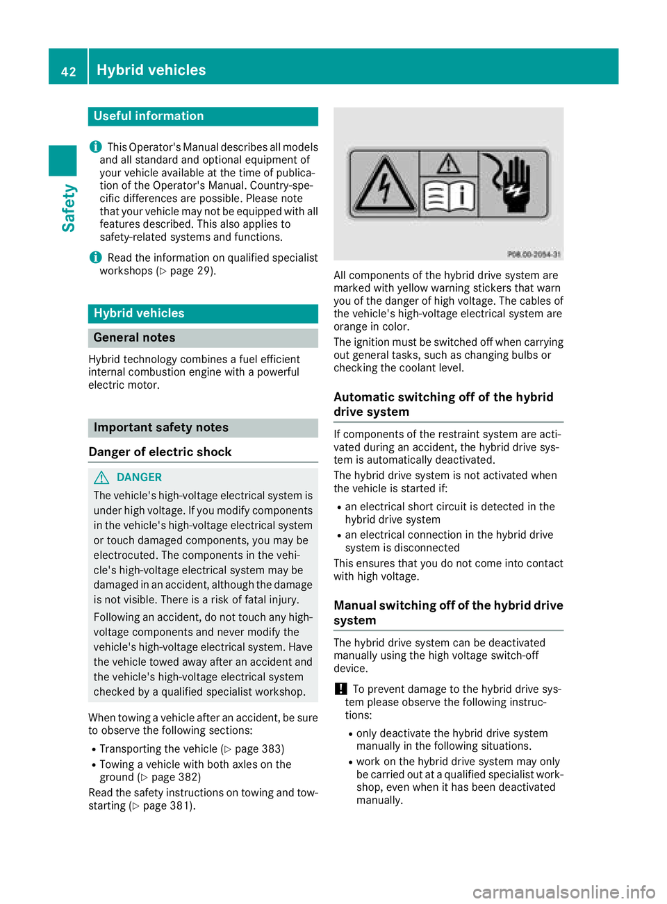
page 381). All components of the hybrid drive system are
marked with yellow warning stickers that warn
you of the danger of high voltage. The cables of
the vehicle's high-voltage electrical system are
orange in color.
The ignition must be switched off when carrying
out general tasks, such as changing bulbs or
checking the coolant level.
Automatic switching off of the hybrid
drive system If components of the restraint system are acti-
vated during an accident, the hybrid drive sys-
tem is automatically deactivated.
The hybrid drive system is not activated when
the vehicle is started if: R
an electrical short circuit is detected in the
hybrid drive system R
an electrical connection in the hybrid drive
system is disconnected
This ensures that you do not come into contact
with high voltage.
Manual switching off of the hybrid drive
system The hybrid drive system can be deactivated
manually using the high voltage switch-off
device.
! To prevent damage to the hybrid drive sys-
tem please observe the following instruc-
tions: R
only deactivate the hybrid drive system
manually in the following situations. R
work on the hybrid drive system may only
be carried out at a qualified specialist work-
shop, even when it has been deactivated
manually.42
Hybrid vehicles
Safety
Page 173 of 450
energy and stored in the high-voltage battery.
Information on overrun mode ( Y
page 253).
The high-voltage battery can be charged as fol-
lows: R
through energy recuperation while the vehicle
is in motion R
through the combustion engine while driving
in CHARGE operating mode ( Y
page 246)R
with the relevant charging cable at an electri-
cal outlet while the vehicle is stationary R
at a wallbox while the vehicle is stationary R
at a charging station while the vehicle is sta-
tionary
The high-voltage battery can be charged in a
nominal voltage range from 100 V to 240 V.
You can view the condition of charge of the high-
voltage battery in the multifunction display. You
can find information in "PLUG-IN HYBRID oper-
ation", section "Menus and submenus" under
"Energy flow display" ( Y
page 247).
High and low outside temperatures Low outside temperatures
At very low outside temperatures the maximum
power output of the high-voltage battery may be
reduced. The high-voltage battery is then no
longer able to provide the normal electrical
power output.
High outside temperatures
To prevent damage to the high-voltage battery
due to very high outside temperatures, the max-
imum power output of the high-voltage battery
is reduced by the vehicle.
Energy consumption and electrical
range The maximum electrical range is generally
reduced by: R
high and low outside temperatures R
operating the climate control system R
switching on consumers
The battery's physical characteristics are such
that leaving the vehicle parked for long periods
at low outdoor temperatures without charging it
can lead to: R
a reduction in battery performance R
longer charge times Notes on battery care Avoid storing or transporting the vehicle at
excessively high or low temperatures over a long
period.
If you park the vehicle and leave it stationary for
long periods: R
check the condition of charge of the high-
voltage battery more often R
connect the vehicle to a power supply
This prevents self-discharge and damage to the
high-voltage battery.
Terms of use Please note the information on exceptions and
limitations in warranty documentation and in
the Maintenance Booklet.
Handling the charging cable and charg-
ing cable controls Do not leave the charging cable controls
( Y
page 172) hanging loose from an electrical
outlet. Otherwise, this could result in a poor
contact with the electrical outlet and malfunc-
tions when charging the vehicle.
To ensure that the brackets within the charging
cable controls are not subjected to incorrect
loads, observe the following: R
Never lift or carry the controls by the charging
cable connector or the mains plug. R
To transport the charging cable, the charging
cable can be: -
wrapped around the controls or -
secured to the housing of the controls
Heat generated by the charging cable
and charging cable connector Pay attention to the "Important safety notes"
( Y
page 169).
During the charging process, the charging cable
and charging cable connector may heat up.
The charging cable and the charging cable con-
nector will only heat up within the permissible
limiting values, provided that: R
the power supply and the charging cable are
not damaged R
the instructions for handling the charging
cable and controls on the charging cable are
observedCharging the high-voltage battery 171
Driving and parking Z
Page 185 of 450
The ECO display consists of three sections, with
an inner and outer area. The sections corre-
spond to the following three categories:
�C
Acceleration (evaluation of all accel-
eration processes): R
the outer area fills up and the inner
area lights up green: moderate
acceleration, especially at higher
speeds R
the outer area empties and the
inner area is gray: sporty acceler-
ation
�D
Coasting (evaluation of all decelera-
tion processes): R
the outer area fills up and the inner
area lights up green: anticipatory
driving, keeping your distance and
early release of the accelerator.
The vehicle can coast without use
of the brakes. R
the outer area empties and the
inner area is gray: frequent heavy
braking
�
Page 208 of 450
Make sure no one is underneath the vehicle or
in the immediate vicinity of the wheel arches
when the vehicle is being lowered.
If you unlock the vehicle or open a door, the
vehicle begins to compensate for load discrep-
ancies while still parked. However, for signifi-
cant level changes, such as after the vehicle has
been stationary for a long period, the engine
must be on. For safety reasons, the vehicle is
only lowered when the doors are closed. Low-
ering is interrupted if a door is opened, and it
continues once the door has been closed.
ADS and ADS PLUS (Adaptive Damping
System) General notes The Adaptive Damping System automatically
controls the calibration of the dampers. The
damping characteristics adapt to the current
operating and driving situation.
The damping is tuned individually to each wheel
and depends on: R
your driving style, e.g. sporty R
the road surface conditions R
the drive program selected R
the vehicle level setting
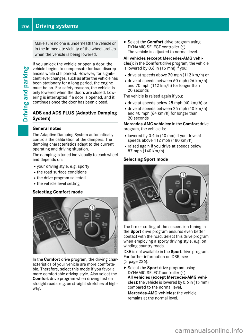
Selecting Comfort mode
In the Comfort drive program, the driving char-
acteristics of your vehicle are more comforta-
ble. Therefore, select this mode if you favor a
more comfortable driving style. Also select the
Comfort drive program when driving fast on
straight roads, e.g. on straight stretches of high-
way. X
Select the Comfort drive program using
DYNAMIC SELECT controller �C .
The vehicle is adjusted to normal level.
All vehicles (except Mercedes-AMG vehi-
cles): in the Comfort drive program, the vehicle
is lowered by 0.6 in (15 mm) if you: R
drive at speeds above 70 mph (112 km/h) or R
drive at speeds between 60 mph (96 km/h)
and 70 mph (112 km/h) for longer than
20 seconds
The vehicle is raised again if you: R
drive at speeds below 25 mph (40 km/h) or R
drive at speeds between 25 mph (40 km/h)
and 40 mph (64 km/h) for longer than
20 seconds
Mercedes-AMG vehicles: in the Comfort drive
program, the vehicle is: R
lowered by 0.4 in (10 mm) if you drive at
speeds above 112 mph (180 km/h) R
raised again if you drive at speeds below
87 mph (140 km/h)
Selecting Sport mode
The firmer setting of the suspension tuning in
the Sport drive program ensures even better
contact with the road. Select this drive program
when employing a sporty driving style, e.g. on
winding country roads.
DSR is not available in the Sport drive program.
For further information on DSR, see
( Y
page 236). X
Select the Sport drive program using
DYNAMIC SELECT controller �C .
All vehicles (except Mercedes-AMG vehi-
cles): the vehicle is lowered by 0.6 in (15 mm)
compared to the normal level.
Mercedes-AMG vehicles: the vehicle
remains at the normal level.206
Driving systems
Driving and parking
Page 211 of 450
Setting the normal vehicle level
! Make sure that there is enough ground
clearance when the vehicle is being lowered.
It could otherwise hit the ground, damaging
the underbody.
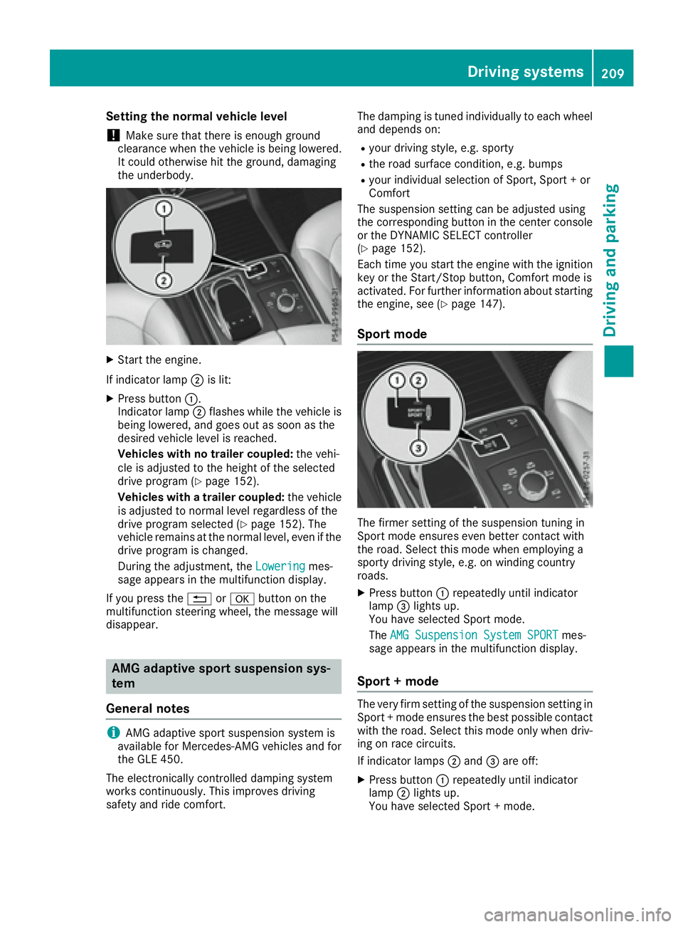
X
Start the engine.
If indicator lamp �D is lit:X
Press button �C .
Indicator lamp �D flashes while the vehicle is
being lowered, and goes out as soon as the
desired vehicle level is reached.
Vehicles with no trailer coupled: the vehi-
cle is adjusted to the height of the selected
drive program ( Y
page 152).
Vehicles with a trailer coupled: the vehicle
is adjusted to normal level regardless of the
drive program selected ( Y
page 152). The
vehicle remains at the normal level, even if the
drive program is changed.
During the adjustment, the Lowering mes-
sage appears in the multifunction display.
If you press the �8 or �v button on the
multifunction steering wheel, the message will
disappear.
AMG adaptive sport suspension sys-
tem
General notes
i AMG adaptive sport suspension system is
available for Mercedes-AMG vehicles and for
the GLE 450.
The electronically controlled damping system
works continuously. This improves driving
safety and ride comfort. The damping is tuned individually to each wheel
and depends on: R
your driving style, e.g. sporty R
the road surface condition, e.g. bumps R
your individual selection of Sport, Sport + or
Comfort
The suspension setting can be adjusted using
the corresponding button in the center console
or the DYNAMIC SELECT controller
( Y
page 152).
Each time you start the engine with the ignition
key or the Start/Stop button, Comfort mode is
activated. For further information about starting
the engine, see ( Y
page 147).
Sport mode
The firmer setting of the suspension tuning in
Sport mode ensures even better contact with
the road. Select this mode when employing a
sporty driving style, e.g. on winding country
roads. X
Press button �C repeatedly until indicator
lamp �
Page 212 of 450
The AMG Suspension System SPORT + mes-
sage appears in the multifunction display.
In "Sport +" mode, the vehicle is lowered by
10 mm compared to the normal level.
Comfort mode In Comfort mode, the driving characteristics of
your vehicle are more comfortable. Select this
mode if you favor a more comfortable driving
style, but also when driving fast on straight
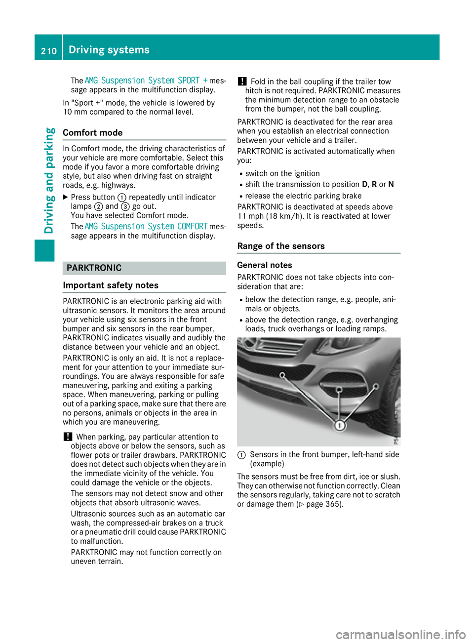
roads, e.g. highways. X
Press button �C repeatedly until indicator
lamps �D and �