2016 MERCEDES-BENZ GLE-CLASS SUV height
[x] Cancel search: heightPage 359 of 450
!Make sure that the windshield wipers are
not folded away from the windshield. You
could otherwise damage the windshield wip-
ers or the hood.
XMake sure that the windshield wipers are
turned off.
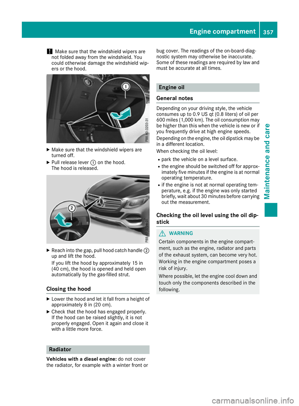
XPull release lever :on the hood.
The hood is released.
XReach into the gap, pull hood catch handle ;
up and lift the hood.
If you lift the hood by approximately 15 in
(40 cm), the hood is opened and held open
automatically by the gas-filled strut.
Closing the hood
XLower the hood and let it fall from a height of
approximately 8 in (20 cm).
XCheck that the hood has engaged properly.
If the hood can be raised slightly, it is not
properly engaged. Open it again and close it
with a little more force.
Radiator
Vehicles with a diesel engine: do not cover
the radiator, for example with a winter front or bug cover. The readings of the on-board-diag-
nostic system may otherwise be inaccurate.
Some of these readings are required by law and
must be accurate at all times.
Engine oil
General notes
Depending on your driving style, the vehicle
consumes up to 0.9 US qt (0.8 liters) of oil per
600 miles (1,000 km). The oil consumption may
be higher than this when the vehicle is new or if
you frequently drive at high engine speeds.
Depending on the engine, the oil dipstick may be
in a different location.
When checking the oil level:
Rpark the vehicle on a level surface.
Rthe engine should be switched off for approx-
imately five minutes if the engine is at normal
operating temperature.
Rif the engine is not at normal operating tem-
perature, e.g. if the engine was only started
briefly, wait about 30 minutes before carrying
out the measurement.
Checking the oil level using the oil dip-
stick
GWARNING
Certain components in the engine compart-
ment, such as the engine, radiator and parts
of the exhaust system, can become very hot.
Working in the engine compartment poses a
risk of injury.
Where possible, let the engine cool down and touch only the components described in the
following.
Engine compartment357
Maintenance and care
Z
Page 392 of 450
Once the winter tires are mounted:
XCheck the tire pressures (Ypage 393).
XRestart the tire pressure monitor
(Ypage 394).
XVehicles for Canada:restart the tire pres-
sure loss warning system (Ypage 394).
Information about driving with an emergency
spare wheel (
Ypage 426).
Snow chains
GWARNING
If snow chains are installed to the front
wheels, they may drag against the vehicle
body or chassis components. This could
cause damage to the vehicle or the tires.
There is a risk of an accident.
To avoid hazardous situations:
Rnever install snow chains to the front
wheels
Ralways install snow chains in pairs to the
rear wheels.
!You must drive at raised vehicle level (height
1) if snow chains have been installed. The
vehicle may otherwise be damaged.
!Vehicles with ADS (Adaptive Damping
System): do not use the sport mode when
driving with snow chains mounted. The vehi-
cle may otherwise be damaged.
!On some tire sizes there is not enough space
for snow chains. To avoid damage to the vehi-
cle or tires, observe the "Wheel and tire com-
binations" section under "Tires and wheels".
For safety reasons, Mercedes-Benz recom-
mends that you only use snow chains that have
been specially approved for your vehicle by
Mercedes-Benz, or are of a corresponding
standard of quality. For more information,
please contact a qualified specialist workshop.
If you intend to mount snow chains, please bear
the following points in mind:
ROnly use snow chains when driving on roads
completely covered by snow. Remove the snow chains as soon as possible when you
come to a road that is not snow-covered.
Rdo not exceed the maximum permissible
speed of 30 mph (50 km/h).
RLocal regulations may restrict the use of snow
chains. Observe the appropriate regulations if
you wish to mount snow chains.
RSnow chains may not be mounted on all
wheel/tire combinations. Permissible wheel-
tire combinations (
Ypage 413).
You may wish to deactivate ESP®when pulling
away with snow chains installed (Ypage 72).
You can thereby allow the wheels to spin in a
controlled manner, achieving an increased driv-
ing force (cutting action).
Information about driving with an emergency
spare wheel (
Ypage 426).
Tire pressure
Tire pressure specifications
Important safety notes
GWARNING
Underinflated or overinflated tires pose the
following risks:
Rthe tires may burst, especially as the load
and vehicle speed increase.
Rthe tires may wear excessively and/or
unevenly, which may greatly impair tire
traction.
Rthe driving characteristics, as well as steer-
ing and braking, may be greatly impaired.
There is a risk of an accident.
Follow recommended tire inflation pressures
and check the pressure of all the tires includ-
ing the spare wheel:
Rmonthly, at least
Rif the load changes
Rbefore beginning a long journey
Runder different operating conditions, e.g.
off-road driving
If necessary, correct the tire pressure.
The data on the Tire and Loading Information
placard and tire pressure table shown here are
390Tire pressure
Wheels and tires
Page 405 of 450
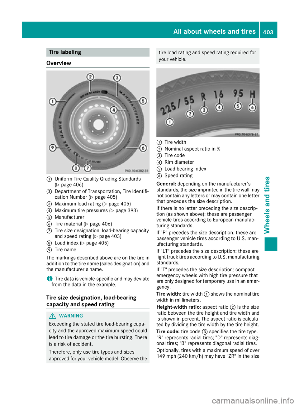
Tire labeling
Overview
:Uniform Tire Quality Grading Standards
(Ypage 406)
;Department of Transportation, Tire Identifi-
cation Number (Ypage 405)
=Maximum load rating (Ypage 405)
?Maximum tire pressures (Ypage 393)
AManufacturer
BTire material (Ypage 406)
CTire size designation, load-bearing capacity
and speed rating (Ypage 403)
DLoad index (Ypage 405)
ETire name
The markings described above are on the tire in
addition to the tire name (sales designation) and
the manufacturer's name.
iTire data is vehicle-specific and may deviate
from the data in the example.
Tire size designation, load-bearing
capacity and speed rating
GWARNING
Exceeding the stated tire load-bearing capa-
city and the approved maximum speed could
lead to tire damage or the tire bursting. There is a risk of accident.
Therefore, only use tire types and sizes
approved for your vehicle model. Observe the
tire load rating and speed rating required for
your vehicle.
:Tire width
;Nominal aspect ratio in %
=Tire code
?Rim diameter
ALoad bearing index
BSpeed rating
General: depending on the manufacturer's
standards, the size imprinted in the tire wall may
not contain any letters or may contain one letter
that precedes the size description.
If there is no letter preceding the size descrip-
tion (as shown above): these are passenger
vehicle tires according to European manufac-
turing standards.
If "P" precedes the size description: these are
passenger vehicle tires according to U.S. man-
ufacturing standards.
If "LT" precedes the size description: these are
light truck tires according to U.S. manufacturing
standards.
If "T" precedes the size description: compact
emergency wheels with high tire pressure that
are only designed for temporary use in an emer-
gency.
Tire width: tire width:shows the nominal tire
width in millimeters.
Height-width ratio: aspect ratio;is the size
ratio between the tire height and tire width and
is shown in percent. The aspect ratio is calcula-
ted by dividing the tire width by the tire height.
Tire code: tire code=specifies the tire type.
"R" represents radial tires; "D" represents diag-
onal tires
; "B" represents diagonal radial tires.
Optionally, tires with a maximum speed of over
149 mph (240 km/h) may have "ZR" in the size
All about wheels an d tires403
Wheels and tires
Z
Page 409 of 450
Speed rating
The speed rating is part of the tire identification.It specifies the speed range for which the tire is
approved.
GTW (Gross Trailer Weight)
The GTW is the weight of a trailer including the
weight of the load, luggage, accessories etc. on
the trailer.
GVW (Gross Vehicle Weight)
The gross vehicle weight includes the weight of
the vehicle including fuel, tools, the spare wheel,
accessories installed, occupants, luggage and
the drawbar noseweight, if applicable. The gross
vehicle weight must not exceed the gross vehi-
cle weight rating GVWR as specified on the vehi- cle identification plate on the B-pillar on the
driver's side.
GVWR (Gross Vehicle Weight Rating)
The GVWR is the maximum permissible gross
weight of a fully loaded vehicle (the weight of the
vehicle including all accessories, occupants,
fuel, luggage and the drawbar noseweight, if
applicable). The gross vehicle weight rating is
specified on the vehicle identification plate on
the B-pillar on the driver's side.
Maximum loaded vehicle weight
The maximum weight is the sum of:
Rthe curb weight of the vehicle
Rthe weight of the accessories
Rthe load limit
Rthe weight of the factory installed optional
equipment
Kilopascal (kPa)
Metric unit for tire pressure. 6.9 kPa corre-
sponds to 1 psi. Another unit for tire pressure is
bar. 100 kilopascals (kPa) are the equivalent of
1 bar.
Load index
In addition to the load-bearing index, the load
index may also be imprinted on the sidewall of
the tire. This specifies the load-bearing capacity
more precisely.
Curb weight
The weight of a vehicle with standard equipment
including the maximum capacity of fuel, oil and
coolant. It also includes the air-conditioning sys- tem and optional equipment if these are instal-
led in the vehicle, but does not include passen-
gers or luggage.
Maximum load rating
The maximum tire load is the maximum permis-
sible weight in kilograms or lbs for which a tire is approved.
Maximum permissible tire pressure
Maximum permissible tire pressure for one tire.
Maximum load on one tire
Maximum load on one tire. This is calculated by
dividing the maximum axle load of one axle by
two.
PSI (pounds per square inch)
A standard unit of measure for tire pressure.
Aspect ratio
Relationship between tire height and tire widt h
in percent.
Tire pressure
This is pressure inside the tire applying an out-
ward force to each square inch of the tire's sur-
face. The tire pressure is specified in pounds per
square inch (psi), in kilopascal (kPa) or in bar.
The tire pressure should only be corrected when the tires are cold.
Cold tire pressure
The tires are cold:
Rif the vehicle has been parked with the tires
out of direct sunlight for at least three hours
and
Rif the vehicle has not been driven further than
1 mile (1.6 km)
Tread
The part of the tire that comes into contact with
the road.
Bead
The tire bead ensures that the tire sits securely
on the wheel. There are several steel wires in the
bead to prevent the tire from coming loose from
the wheel rim.
All about wheels and tires407
Wheels and tires
Z
Page 412 of 450

XPlace chocks or other suitable items under
the front and rear of the wheel that is diago-
nally opposite the wheel you wish to change.
Raising the vehicle
GWARNING
If you do not position the jack correctly at the
appropriate jacking point of the vehicle, the
jack could tip over with the vehicle raised.
There is a risk of injury.
Only position the jack at the appropriate jack-
ing point of the vehicle. The base of the jack
must be positioned vertically, directly under
the jacking point of the vehicle.
!The jack is designed exclusively for jacking
up the vehicle at the jacking points. Other-
wise, your vehicle could be damaged.
Observe the following when raising the vehi-
cle:
RTo raise the vehicle, only use the vehicle-spe-
cific jack that has been tested and approved
by Mercedes-Benz. If used incorrectly, the
jack could tip over with the vehicle raised.
RThe jack is designed only to raise and hold the
vehicle for a short time while a wheel is being
changed. It must not be used for performing
maintenance work under the vehicle.
RAvoid changing the wheel on uphill and down-
hill slopes.
RBefore raising the vehicle, secure it from roll-
ing away by applying the parking brake and
inserting wheel chocks. Do not disengage the
parking brake while the vehicle is raised.
RThe jack must be placed on a firm, flat and
non-slip surface. On a loose surface, a large,
flat, load-bearing underlay must be used. On a slippery surface, a non-slip underlay must be
used, e.g. rubber mats.
RDo not use wooden blocks or similar objects
as a jack underlay. Otherwise, the jack will not
be able to achieve its load-bearing capacity
due to the restricted height.
RMake sure that the distance between the
underside of the tires and the ground does not
exceed 1.2 in (3 cm).
RDo not place your hands or feet under the
raised vehicle.
RDo not lie under the vehicle.
RDo not start the engine when the vehicle is
raised.
RNever open or close a door or the tailgate
when the vehicle is raised.
RMake sure that no persons are present in the
vehicle when the vehicle is raised.
XUsing lug wrench :, loosen the bolts on the
wheel you wish to change by about one full
turn. Do not unscrew the bolts completely.
The jacking points are located just behind the
front wheel housings and just in front of the rear
wheel housings (arrows).
XTake the ratchet wrench out of the vehicle
tool kit and place it on the hexagon nut of the
jack so that the letters AUFare visible.
410Changing a wheel
Wheels and tires
Page 443 of 450
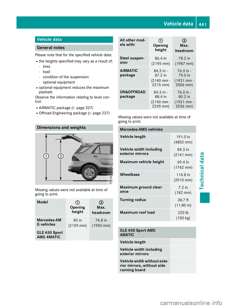
Vehicle data
General notes
Please note that for the specified vehicle data:
Rthe heights specified may vary as a result of:
-tires
-load
-condition of the suspension
-optional equipment
Roptional equipment reduces the maximum
payload.
Observe the information relating to level con-
trol:
RAIRMATIC package (Ypage 207)
ROffroad Engineering package (Ypage 237)
Dimensions and weights
Missing values were not available at time of
going to print.
Model:
Opening height
;
Max.
headroom
Mercedes ‑AM
G vehicles85 in
(2159 mm)76.8 in
(1950 mm)
GLE 450 Sport
AMG 4MATIC
All other mod-
els with::
Opening height
;
Max.
headroom
Steel suspen-
sion86.4 in
(2195 mm)78.2 in
(1987 mm)
AIRMATIC
package84.3 in - 87.2 in
(2140 mm - 2215 mm)76.0 in -79.0 in
(1931 mm - 2006 mm)
ON&OFFROAD
package84.3 in -88.4 in
(2140 mm - 2245 mm)76.0 in -80.2 in
(1931 mm - 2036 mm)
Missing values were not available at time of
going to print.
Mercedes ‑AMG vehicles
Vehicle length191.0 in
(4852 mm)
Vehicle width including
exterior mirrors84.3 in
(2141 mm)
Maximum vehicle height69.4 in
(1762 mm)
Wheelbase114.8 in
(2915 mm)
Maximum ground clear-
ance7.2 in
(182 mm)
Turning radius38.7 ft
(11.80 m)
Maximum roof load220 lb
(100 kg)
GLE 450 Sport AMG
4MATIC
Vehicle length
Vehicle width including
exterior mirrors
Vehicle width without exte-
rior mirrors, without side
running board
Vehicle data441
Technical data
Z
Page 444 of 450
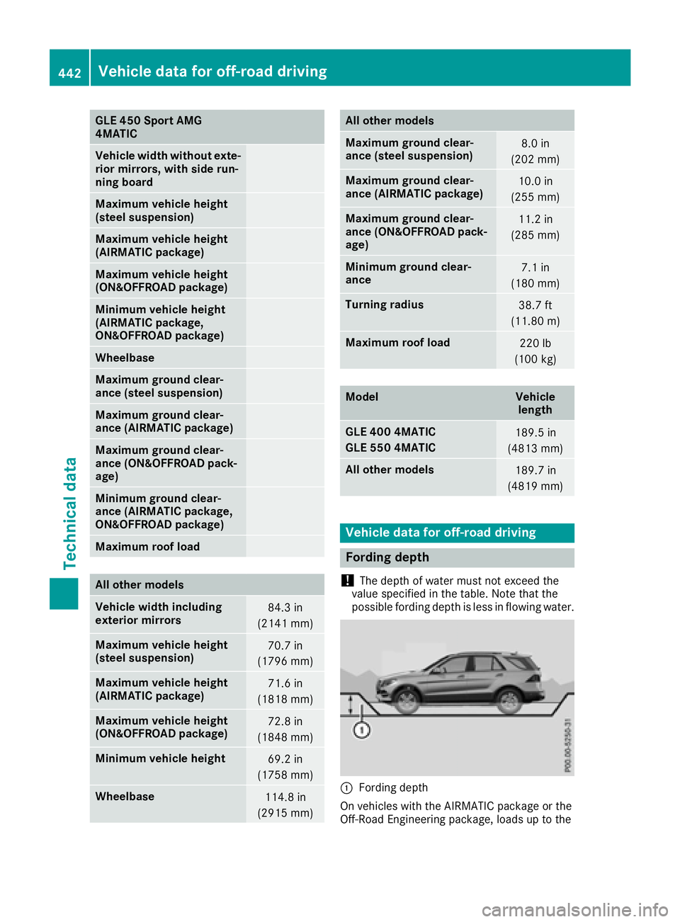
GLE 450 Sport AMG
4MATIC
Vehicle width without exte-
rior mirrors, with side run-
ning board
Maximum vehicle height
(steel suspension)
Maximum vehicle height
(AIRMATIC package)
Maximum vehicle height
(ON&OFFROAD package)
Minimum vehicle height
(AIRMATIC package,
ON&OFFROAD package)
Wheelbase
Maximum ground clear-
ance (steel suspension)
Maximum ground clear-
ance (AIRMATIC package)
Maximum ground clear-
ance (ON&OFFROAD pack-
age)
Minimum ground clear-
ance (AIRMATIC package,
ON&OFFROAD package)
Maximum roof load
All other models
Vehicle width including
exterior mirrors84.3 in
(2141 mm)
Maximum vehicle height
(steel suspension)70.7 in
(1796 mm)
Maximum vehicle height
(AIRMATIC package)71.6 in
(1818 mm)
Maximum vehicle height
(ON&OFFROAD package)72.8 in
(1848 mm)
Minimum vehicle height69.2 in
(1758 mm)
Wheelbase114.8 in
(2915 mm)
All other models
Maximum ground clear-
ance (steel suspension)8.0 in
(202 mm)
Maximum ground clear-
ance (AIRMATIC package)10.0 in
(255 mm)
Maximum ground clear-
ance (ON&OFFROAD pack-
age)11.2 in
(285 mm)
Minimum ground clear-
ance7.1 in
(180 mm)
Turning radius38.7 ft
(11.80 m)
Maximum roof load220 lb
(100 kg)
ModelVehicle length
GLE 400 4MATIC
GLE 550 4MATIC189.5 in
(4813 mm)
All other models189.7 in
(4819 mm)
Vehicle data for off-road driving
Fording depth
!
The depth of water must not exceed the
value specified in the table. Note that the
possible fording depth is less in flowing water.
:Fording depth
On vehicles with the AIRMATIC package or the
Off-Road Engineering package, loads up to the
442Vehicle data for off-road driving
Technical data