2016 MERCEDES-BENZ GLE-CLASS SUV light
[x] Cancel search: lightPage 167 of 450

:To open the fuel filler flap
;To insert the fuel filler cap
=Instruction label for fuel type to be refueled
?Tire pressure table
XPress the fuel filler flap in the direction of
arrow:.
The fuel filler flap swings up.
XTurn the fuel filler cap counterclockwise and
remove it.
XInsert the fuel filler cap into the holder on the
inside of the fuel filler flap.
XCompletely insert the filler neck of the fuel
pump nozzle into the tank, hook in place and
refuel.
XOnly fill the tank until the pump nozzle
switches off.
Do not add any more fuel after the pump stops filling for the first time. Otherwise, fuel may
leak out.
Closing the fuel filler flap
XReplace the cap on the filler neck and turn
clockwise until it engages audibly.
XClose the fuel filler flap.
Close the fuel filler flap before locking the vehi-
cle.
If you drive at speeds above 1 mph (2 km/h)
with the fuel filler flap open, the Fuel Filler
Flap Openmessage is shown in the multifunc-
tion display.
If you are driving with the fuel filler cap open, the
8 reserve fuel warning lamp flashes. A mes-
sage appears in the multifunction display
(
Ypage 297).
In addition, the ;Check Engine warning
lamp may light up (
Ypage 325).
iFor further information on warning and indi-
cator lamps in the instrument cluster, see
(
Ypage 325).
Refueling165
Driving and parking
Z
Page 174 of 450
If the charging cable or charging cable connec-
tor become too hot, have the mains power sup-
ply checked.
Protection device against overvoltage
!Overvoltage in the mains supply may dam-
age the vehicle. For this reason, the vehicle is equipped with a protection device against
overvoltage in the mains supply. This device
may be triggered during severe thunder-
storms, for example, and may lead to the buil-
ding's fuse being tripped and an interruption
in the power supply. These functions protect
the vehicle. After the building fuse is switched
on again, the charging process resumes auto-
matically. Following an interruption in the
power supply or tripping of the building's fuse,
it may take up to 10 minutes for charging to
resume automatically.
Switch on the building protection system again
after it has been triggered. Otherwise, the
charging process cannot be continued.
General information about the charging
procedure
Pay attention to the "Important safety notes"
(Ypage 169).
The vehicle socket is located in the rear bumper
on the right below the tail lamp.
The charge socket flap and the vehicle are cen-
trally locked or unlocked simultaneously.
Charging the high-voltage battery via
the electrical outlet
Charging cable for electrical outlets
Important safety notes
!Only use the charging cable to charge the
high-voltage battery. Do not use the charging
cable for other purposes. It may otherwise be
damaged.
The vehicle is supplied with a country-specific
charging cable for connection to a mains socket.
Only use the charging cable supplied with the
vehicle or a charging cable approved for the
vehicle.
iIf you use the supplied 12 A charging cable
to charge a high-voltage battery:
Rthe charge time increases considerably
Relectrical consumption increases consider-
ably
Where possible, charge the high-voltage bat-
tery at a charging station (
Ypage 175). Only
then can certified electrical energy consump-
tion levels be reached.
iThe charging process can vary depending on
the power supply. Therefore, always observe
the local information.
Information about charging from a wallbox
(
Ypage 175).
Information on charging at a charging station
(
Ypage 175).
Stowing the charging cable
The charging cable can be stowed and secured
in the bag provided in the cargo compartment of
the vehicle.
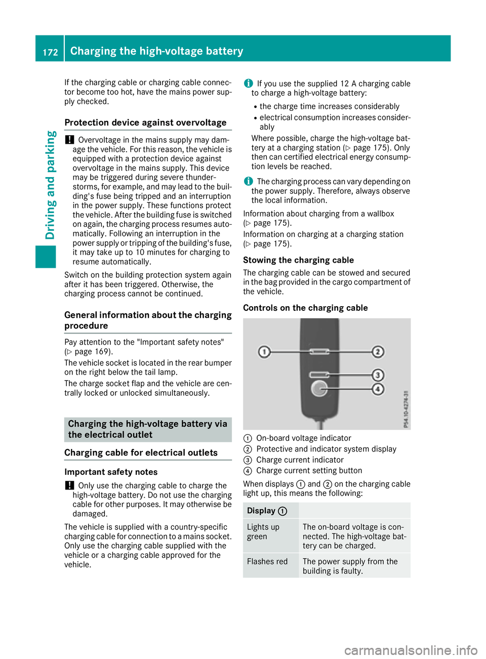
Controls on the charging cable
:On-board voltage indicator
;Protective and indicator system display
=Charge current indicator
?Charge current setting button
When displays :and ;on the charging cable
light up, this means the following:
Display :
Lights up
greenThe on-board voltage is con-
nected. The high-voltage bat-
tery can be charged.
Flashes redThe power supply from the
building is faulty.
172Charging the high-voltage battery
Driving and parking
Page 175 of 450
Display;
Lightsup
greenThere are no malfunctions.
The high-voltage battery can
be charged.
Flashes redThe protective and indicator
system has detecte d amal-
function due to an internal
malfunction .The high-voltage
battery canno tbe charged.
If th econtrol detects residual curren tor amal-
function ,th echarging process is halted. Once
th emalfunction has been rectifie dth echarging
process is resumed automatically.
Fo rinformation on problem srelating to th e
charging process, see (
Ypage 176).
Setting themaximum charg ecurren t
GWARNIN G
If th echarg ecurren tdraw via amain ssocke t
is to ohigh during th echarging process, th e
external electrical system may overheat.
There is aris kof fire.
Befor ebeginning th echarging process, chec k
th emaximum permissibl echarg ecurren t
locally. Consult aqualified exper tto do so
wher enecessary.
If necessary, adjust your vehicle's settings.
!An excessive charg ecurren tcan blow afus e
or lead to overheating of th eexternal powe r
supply. Chec kwhether th eexternal powe r
supply is compatible wit hth eset charg ecur -
rent. If necessary, lower th eset charg ecur -
ren tor use another powe rsocket.
Befor estarting th echarging process at apowe r
socket, chec kth emaximum permissibl echarg e
curren tfor th erelevan tpowe rsocke tor th e
building .
You can set th emaximum permissibl echarg e
current:
Ron th echarging cable control s
Rin theSettingsmen uof th eon-boar dcom-
puter (Ypage 273)
The lower value of th etwo charg ecurren tset -
ting s –on th echarg ecable control sand in th e
on-boar dcomputer –determine sth emaximum
charg ecurrent. If you canno tset th eprecis e maximum permitte
dcharg ecurrent, select th e
next lowes tavailable value .
Only set th emaximum permitte dcharg ecurren t
in th eon-boar dcomputer men uif:
Rit is no tpossibl eto set th echarg ecurren ton
th echarging cable
Rth eprecis emaximum permitte dcharg ecur -
ren tcan only be set via th eon-boar dcom-
puter
Setting th emaximum permitte dcharg ecurren t
on th echarging cable is described below.
XTo adjust th esetting: press butto n?
repeatedly until th edesire dsetting is selec-
te din display =.
RTwo LEDs are flashing: minimum setting
RAllLEDs are flashing: maximum setting
If ,after th echarging process, th echarging cable
is:
Rlef tconnecte dto th epowe rsocket, th ecur -
rentl yselected value swill be used for th enext
charging process.
Rremove dfrom th epowe rsocket, th evalue s
will be reset to th eminimum setting for th e
next charging process. You ma
y then need to
reset th evalue sof th emaximum charg ecur -
rent.
iIf th evehicl erequire smor etime than usual
when charging ,chec kth emaximum charg e
curren tsetting susin gth econtrol son th e
charging cable or in th eon-boar dcomputer' s
menu.
Indicator lam pon th evehicle socket
Whe nth eindicator lamp on th evehicl esocke t
lights up, this mean sth efollowing:
Indicator
lam p
Flashes
orang eThe connection between th e
vehicl eand th ecurren t
source is bein gestablished
before charging begins .
Flashes
greenThe high-voltage battery is
beingcharged.
Flashes redA malfunction has occurred
while charging .
The indicator lamp goe sout
after approximately
90 seconds.
Charging the high-voltage battery17 3
Driving an d parking
Z
Page 176 of 450
Indicator
lamp
Lights up
orangeA charging break for the high-
voltage battery is taking
place.
The indicator lamp goes out
after approximately
90 seconds.
Lights up
greenThe high-voltage battery is
fully charged.
The indicator lamp goes out
after approximately
90 seconds.
iIf the indicator lamp is off, lock or unlock the
vehicle. The indicator lamp then displays the
current status of the charging process again.
Connecting the charging cable
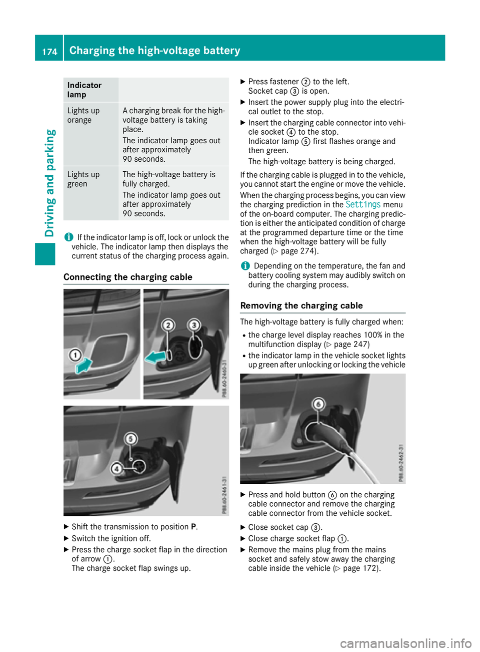
XShift the transmission to position P.
XSwitch the ignition off.
XPress the charge socket flap in the direction
of arrow:.
The charge socket flap swings up.
XPress fastener ;to the left.
Socket cap =is open.
XInsert the power supply plug into the electri-
cal outlet to the stop.
XInsert the charging cable connector into vehi-
cle socket ?to the stop.
Indicator lamp Afirst flashes orange and
then green.
The high-voltage battery is being charged.
If the charging cable is plugged in to the vehicle, you cannot start the engine or move the vehicle.
When the charging process begins, you can view
the charging prediction in the Settings
menu
of the on-board computer. The charging predic-
tion is either the anticipated condition of charge
at the programmed departure time or the time
when the high-voltage battery will be fully
charged (
Ypage 274).
iDepending on the temperature, the fan and
battery cooling system may audibly switch on
during the charging process.
Removing the charging cable
The high-voltage battery is fully charged when:
Rthe charge level display reaches 100% in the
multifunction display (Ypage 247)
Rthe indicator lamp in the vehicle socket lights up green after unlocking or locking the vehicle
XPress and hold button Bon the charging
cable connector and remove the charging
cable connector from the vehicle socket.
XClose socket cap =.
XClose charge socket flap :.
XRemove the mains plug from the mains
socket and safely stow away the charging
cable inside the vehicle (
Ypage 172).
174Charging the high-voltage battery
Driving and parking
Page 177 of 450
Charging the high-voltage battery
from the wallbox
General notes
It is recommended that you charge your vehicle
using a wallbox or at a charging station.
Make sure that the maximum charging current is
not limited in the Settings
menu of the on-
board computer. You must select the maximum
value if charging at a wallbox or a charging sta-
tion (
Ypage 273).
Pay attention to the "Important safety notes"
(
Ypage 169).
Connecting the charging cable
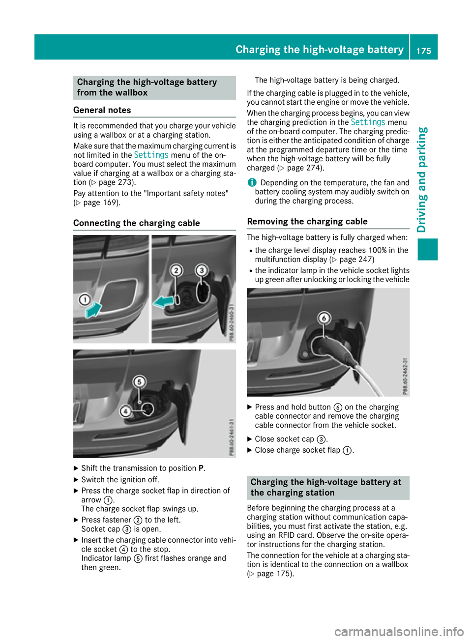
XShift the transmission to position P.
XSwitch the ignition off.
XPress the charge socket flap in direction of
arrow:.
The charge socket flap swings up.
XPress fastener ;to the left.
Socket cap =is open.
XInsert the charging cable connector into vehi-
cle socket ?to the stop.
Indicator lamp Afirst flashes orange and
then green. The high-voltage battery is being charged.
If the charging cable is plugged in to the vehicle, you cannot start the engine or move the vehicle.
When the charging process begins, you can view
the charging prediction in the Settings
menu
of the on-board computer. The charging predic-
tion is either the anticipated condition of charge at the programmed departure time or the time
when the high-voltage battery will be fully
charged (
Ypage 274).
iDepending on the temperature, the fan and
battery cooling system may audibly switch on
during the charging process.
Removing the charging cable
The high-voltage battery is fully charged when:
Rthe charge level display reaches 100% in the
multifunction display (Ypage 247)
Rthe indicator lamp in the vehicle socket lights up green after unlocking or locking the vehicle
XPress and hold button Bon the charging
cable connector and remove the charging
cable connector from the vehicle socket.
XClose socket cap =.
XClose charge socket flap :.
Charging the high-voltage battery at
the charging station
Before beginning the charging process at a
charging station without communication capa-
bilities, you must first activate the station, e.g.
using an RFID card. Observe the on-site opera-
tor instructions for the charging station.
The connection for the vehicle at a charging sta-
tion is identical to the connection on a wallbox
(
Ypage 175).
Charging the high-voltage battery175
Driving and parking
Z
Page 179 of 450
ProblemPossible causes/consequences andMSolutions
The indicator lamp on the vehicle socket does not light up.
The connection between the vehicle and the external current source
cannot be established.
XConnect the charging cable again.
If the problem persists:
XHave the power socket checked or use another power socket.
or
XUse a different charging station.
or
XConsult a qualified specialist workshop.
The charging cable con-
nector cannot be
removed from the vehi-
cle socket.The snap fastener on the charging cable connector is locked.
XPress and hold the button on the charging cable connector. The
snap fastener on the vehicle socket is unlocked.
XRemove the charging cable connector from the vehicle socket.
If the snap fastener on the charging cable connector is locked:
XPress and hold the button on the charging cable connector and try
to release the lock.
Online access to the vehicle
General information
GWARNING
If you operate information systems and com-
munication equipment integrated in the vehi-
cle while driving, you will be distracted from
traffic conditions. You could also lose control
of the vehicle. There is a risk of an accident.
Only operate the equipment when the traffic
situation permits. If you are not sure that this
is possible, park the vehicle paying attention
to traffic conditions and operate the equip-
ment when the vehicle is stationary.
iOperation of integrated information sys-
tems and communications equipment in
the vehicle: you must observe the legal
requirements for the country in which you are currently driving.
You can call up remote query and remote con-
figuration functions for your vehicle using online
access to the vehicle. This is possible from an
Internet-enabled computer, as well as many
modern smartphones. Please call the Mercedes-Benz Customer Assis-
tance Center (USA) at the hotline number
1-800-FOR-MERCedes (1-800-367-6372)
to
obtain the relevant Internet address.
Online access to the vehicle is restricted to the
contractual periods of mbrace. Activated
access to the mbrace emergency call system is
required for use.
In order to be able to use online access to the
vehicle, you must agree to the local terms of
use.
Further information about the supported end
devices, available languages and contractual
periods is available at any authorized Mercedes-
Benz Center.
In order to be able to call up online access to the
vehicle, the vehicle must be connected to the
Internet (Ypage 178).
Notes on data protection
Remember that online access to the vehicle
offers access to your data.
iPrevent unauthorized persons from
accessing this data.
Charging the high-voltage battery177
Driving and parking
Z
Page 182 of 450

The function of the electric parking brake is
dependent on the on-board voltage. If the on-
board voltage is low or there is a malfunction in
the system, it may not be possible to apply the
released parking brake.
XIf this is the case, only park the vehicle on
level ground and secure it to prevent it rolling
away.
XShift the automatic transmission to position
P.
It may not be possible to release an applied
parking brake if the on-board voltage is low or
there is a malfunction in the system. Contact a
qualified specialist workshop.
iThe electric parking brake performs a func-
tion test at regular intervals while the engine
is switched off. The sounds that can be heard
while this is occurring are normal.
Applying or releasing manually
XTo engage: push handle :.
When the electric parking brake is engaged,
the F (USA only) or !(Canada only)
red indicator lamp lights up in the instrument
cluster.
iThe electric parking brake can also be
applied when the SmartKey is removed.
XTo release: pull handle:.
The red F(USA only) or !(Canada
only) indicator lamp in the instrument cluster goes out.
iThe electric parking brake can only be
released:
Rif the SmartKey is in position 1in the igni-
tion lock (Ypage 145) or
Rif the ignition was switched on using the
Start/Stop button To ensure that you do not roll backwards when
pulling away on an uphill slope, engage the elec-
tric parking brake (
Ypage 149).
Applying automatically
The electric parking brake is automatically
applied when the transmission is in position P
and:
Rthe engine is switched off or
Rthe driver is not wearing a seat belt and the
driver's door is opened.
To prevent the electric parking brake from being
automatically applied, pull handle :.
The electric parking brake is also engaged auto- matically if:
RDISTRONIC PLUS brings the vehicle to a
standstill or
Rthe HOLD function is keeping the vehicle sta-tionary
RActive Parking Assist is keeping the vehicle
stationary
In addition, at least one of the following condi-
tions must be fulfilled:
Rthe engine is switched off
Rthe driver is not wearing a seat belt and the
driver's door is opened
Rthere is a system malfunction
Rthe power supply is insufficient
Rthe vehicle is stationary for a lengthy period
The red F(USA only) or !(Canada only)
indicator lamp in the instrument cluster lights
up.
The electric parking brake is not automatically
engaged if the engine is switched off by the ECO
start/stop function.
Releasing automatically
The electric parking brake is released automat-
ically when all of the following conditions are
fulfilled:
Rthe engine is running.
Rthe transmission is in position Dor R.
Rthe seat belt has been fastened.
Ryou depress the accelerator pedal.
If the transmission is in position R, the trunk lid
must be closed.
180Parking
Driving and parking
Page 184 of 450

Drive sensibly–save fuel
Observ eth efollowin gtips to sav efuel:
XThe tires should always be inflate dto th erec -
ommended tire pressure.
XRemov eunnecessary loads.
XRemov eroof carriers when they are no tnee-
ded.
XWar mup th eengin eat low engin espeeds .
XAvoid frequent acceleration or braking .
XHaveall maintenance wor kcarrie dout as
indicated by th eservic eintervals in th eMain -
tenance Booklet or by th eservic einterval dis -
play.
Fue lconsumption also increase swhen drivin gin
cold weather ,in stop-start traffic and in hill yter-
rain .
Drinking an ddrivin g
GWARNING
Drinking and drivin gand/o rtaking drugs and
drivin gare ver ydangerous combinations.
Even asmall amount of alcoho lor drugs can
affec tyour reflexes, perception sand judg-
ment.
The possibilit yof aserious or eve nfatal acci-
den tis greatly increase dwhen you drink or
take drugs and drive.
Do no tdrink or take drugs and drive or allow
anyon eto drive who has bee ndrinkin gor tak-
in g drugs.
Emission contro l
GWARNING
Combustion engines emi tpoisonous exhaus t
gases suc has carbon monoxide. Inhaling
these exhaus tgases lead sto poisoning. There
is aris kof fatal injury. Therefor enever leav e
th eengin erunning in enclose dspaces with-
out sufficien tventilation .
Certain engin esystems are designed to keep
th elevel of poisonous component sin exhaus t
fumes within lega llimits.
These systems only wor kat peak efficiency if
they are serviced exactly in accordance wit hth e
manufacturer's specifications. Always hav ewor
kon th eengin ecarrie dout at aqualified
specialis tworkshop .Mercedes-Ben zrecom -
mends that you use an authorized Mercedes -
Benz Cente rfo rthis purpose. In particular, wor k
relevant to safet yor on safety-related systems
mus tbe carrie dout at aqualified specialis t
workshop .
The engin esetting smus tno tbe changed under
any circumstances. Furthermore, all specific
servic ewor kmus tbe carrie dout at regular
intervals and in accordance wit hth eMercedes -
Benz servic erequirements .Details can be found
in th eMaintenance Booklet .
ECO display
The ECOdisplay shows you how economical
your drivin gstyle is. The EC Odisplay assist syou
in achievin gth emost economical drivin gstyle
fo rth eselecte dsetting sand prevailin gcondi-
tions. Your drivin gstyle can significantly influ-
ence th evehicle' sconsumption .
:Acceleration
;Coasting
=Constant
?Additional range achieved
Range ?is shown under Bonus
fr.Startand
represents th eadditional range achieved since
th ebeginning of th ejourney as aresult of an
adapted drivin gstyle.
If th efue llevel has dropped into th ereserv e
range, th eReserv eFue l
messag eis shown in
th emultifunction display instead of range ?.
The 8 warnin glamp in th einstrumen tcluster
also lights up (
Ypage 325).
182Driving tips
Driving and parking