2016 MERCEDES-BENZ GLE-CLASS COUPE center console
[x] Cancel search: center consolePage 187 of 382
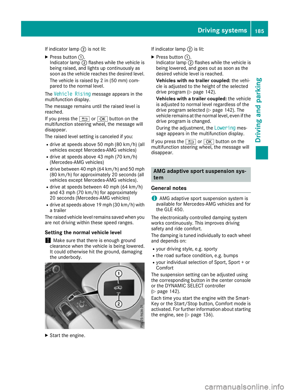
If indicator lamp;is not lit:
XPress button :.
Indicator lamp ;flashes while the vehicle is
being raised, and lights up continuously as
soon as the vehicle reaches the desired level.
The vehicle is raised by 2 in (50 mm) com-
pared to the normal level.
The Vehicle Rising
message appears in the
multifunction display.
The message remains until the raised level is
reached.
If you press the %ora button on the
multifunction steering wheel, the message will
disappear.
The raised level setting is canceled if you:
Rdrive at speeds above 50 mph (80 km/h) (all
vehicles except Mercedes-AMG vehicles)
Rdrive at speeds above 43 mph (70 km/h)
(Mercedes-AMG vehicles)
Rdrive between 40 mph (64 km/h) and 50 mph (80 km/h) for approximately 20 seconds (all
vehicles except Mercedes-AMG vehicles).
Rdrive at speeds between 40 mph (64 km/h)
and 43 mph (70 km/h) for approximately
20 seconds (Mercedes-AMG vehicles)
Rdrive at speeds above 19 mph (30 km/h) with
a trailer
The raised vehicle level remains saved when you
are not driving within these speed ranges.
Setting the normal vehicle level
!Make sure that there is enough ground
clearance when the vehicle is being lowered.
It could otherwise hit the ground, damaging
the underbody.
XStart the engine. If indicator lamp
;is lit:
XPress button :.
Indicator lamp ;flashes while the vehicle is
being lowered, and goes out as soon as the
desired vehicle level is reached.
Vehicles with no trailer coupled: the vehi-
cle is adjusted to the height of the selected
drive program (
Ypage 142).
Vehicles with a trailer coupled: the vehicle
is adjusted to normal level regardless of the
drive program selected (
Ypage 142). The
vehicle remains at the normal level, even if the
drive program is changed.
During the adjustment, the Lowering
mes-
sage appears in the multifunction display.
If you press the %ora button on the
multifunction steering wheel, the message will
disappear.
AMG adaptive sport suspension sys-
tem
General notes
iAMG adaptive sport suspension system is
available for Mercedes-AMG vehicles and for
the GLE 450.
The electronically controlled damping system
works continuously. This improves driving
safety and ride comfort.
The damping is tuned individually to each wheel
and depends on:
Ryour driving style, e.g. sporty
Rthe road surface condition, e.g. bumps
Ryour individual selection of Sport, Sport + or
Comfort
The suspension setting can be adjusted using
the corresponding button in the center console
or the DYNAMIC SELECT controller
(
Ypage 142).
Each time you start the engine with the Smart-
Key or the Start/Stop button, Comfort mode is
activated. For further information about starting
the engine, see (
Ypage 136).
Driving systems185
Driving and parking
Z
Page 200 of 382
Rif there is a sudden change in temperature,
e.g. when driving into a heated garage in win-ter
Rif the camera lenses are dirty or covered
Rif the vehicle components in which the cam-
eras are installed are damaged. In this event,
have the camera position and setting checked
at a qualified specialist workshop
Do not use the 360° camera in this case. You
can otherwise injure others or cause damage to objects or the vehicle.
Guide lines are always shown at road level.
The field of vision and other functions of the
camera system may be restricted due to addi-
tional accessories on the rear of the vehicle (e.g.
license plate holder, bicycle rack).
On vehicles with height-adjustable chassis,
depending on technical conditions, leaving the
standard height can result in:
Rinaccuracies in the guide lines
Rinaccuracies in the display of generated
images (top view)
Activation conditions
The 360° camera image can be displayed if:
Ryour vehicle is equipped with a 360° camera
Rthe SmartKey is in position 2in the ignition
lock
Rthe multimedia system is switched on
Switching on the 360° camera
XPress the Øbutton in the center console
for longer than two seconds.
Depending on whether position Dor Ris
engaged, the following is shown:
Ra split screen with top view and the image
from the front camera or
Ra split screen with top view and the image
from the rear view camera
or
XPress the Øbutton in the center console.
The vehicle menu is displayed.
XSelect 360°Cameraand press 7to confirm.
Depending on whether position Dor Ris
engaged, the following is shown:
Ra split screen with top view and the image
from the front camera or
Ra split screen with top view and the image
from the rear view camera
Activating the 360° camera using
reverse gear
The 360° camera images can be automatically
displayed by engaging reverse gear.
XMake sure that the SmartKey is in position 2
in the ignition lock.
XMake sure that the Activation by R gearfunction is selected in the multimedia system
(see the separate operating instructions).
XTo show the 360° camera image: engage
reverse gear.
The multimedia system shows the area
behind the vehicle in split-screen mode. You
see the top view of the vehicle and the image
from the rear view camera.
Selecting the split-screens or 180° view
Selecting split-screen view
XTo switch to the line with the vehicle icons:
slide 5the controller.
XTo select one of the vehicle icons: turn 3
the controller.
XTo switch to 180° View:turn 3 the con-
troller to select 180° View
and press7to
confirm.
iThe 180°Viewoption is only available in the
following views:
RTop view with picture from the rear view
camera
RTop view with picture from the front camera
Displays in the multimedia system
Important safety notes
The camera system may show a distorted view
of obstacles, show them incorrectly or not at all.
Obstacles are not shown by the system in the
following locations:
Runder the front and rear bumpers
Rvery close to the front and rear bumpers
Rin the area immediately above the tailgate
handle
Rvery close to the exterior mirrors
Rin the transitional areas between the various
cameras in the virtual top view
198Driving systems
Driving and parking
Page 246 of 382

Display messagesPossible causes/consequences andMSolutions
FrontPassengerAir‐bag Disabled SeeOperator' sManual
The front-passenger air bag is deactivated during th ejourney, eve n
though :
Ran adult
or
Raperson of th ecorrespondin gstatur eis on th efront-passenger seat
If additional force sare applie dto th eseat ,th esystem may interpret
th eoccupant's weigh tas lower than it actually is.
GWARNIN G
The front-passenger air bag does no tdeploy during an accident.
There is an increased ris kof injury.
XPull ove rand stop th evehicl esafely as soo nas possible, payin g
attention to roa dand traffic conditions.
XSecur eth evehicl eagainst rollin gaway (Ypage 156).
XSwitchth eignition off .
XHaveth eoccupant get out of th evehicle.
XKee pth eseat unoccupied ,close th efront-passenger door and
switch on th eignition .
XObserveth ePASSENGER AI RBA Gindicator lamp sin th ecenter
console and th emultifunction display and chec kth efollowing:
Seat unoccupied and ignition switched on :
Raself-diagnosis is carrie dout .The PASSENGER AI RBA GOF Fand
PASSENGER AI RBA GON indicator lamp smus tligh tup simulta-
neousl yfor approximately six seconds
Rth ePASSENGER AI RBA GOF Findicator lamp mus tthen ligh tup
and remain lit after th eself -diagnosis .If th eindicator lamp is on ,
OCS (Occupant Classification System) has disabled th efront-
passenger fron tair bag (
Ypage 46 )
RtheFront Passenger Airbag Enable dSee Operator' sManualorFront Passenger Airbag Disabled See Opera‐tor's Manualdisplay message smus tno tbe shown in th emul-
tifunction display
XWait for aperiod of at least 60 seconds until th enecessar ysystem
checks hav ebeen completed.
XMak esur ethat th edisplay message sdo no tappear in th emulti-
function display.
If these condition sare fulfilled ,th efront-passenger seat can be occu-
pied again .Whether th ePASSENGER AI RBA GOF For ON indicator
lamp remain slit or goe sout depend son how OCS classifies th eoccu-
pant.
If th econdition sare no tfulfilled ,th esystem is no toperating correctly.
XVisit aqualified specialist workshop immediately.
Fo rfurther information about th eOccupant Classification System, see
(
Ypage 46) .
244Display messages
On-board computer and displays
Page 247 of 382
Display messagesPossible causes/consequences andMSolutions
FrontPassengerAir‐bag Enable dSeeOperator' sManual
The front-passenger air bag is enabled during th ejourney, eve n
though :
Rachild, asmall adult or an objec tweighing less than th esystem' s
weigh tthreshold is locate don th efront-passenger seat
or
Rth efront-passenger seat is unoccupied
The system may detec tobjects or force sapplyin gadditional weigh ton
th eseat .
GWARNIN G
The air bag may deploy unintentionally.
There is an increased ris kof injury.
XPull ove rand stop th evehicl esafely as soo nas possible, payin g
attention to roa dand traffic conditions.
XSecur eth evehicl eagainst rollin gaway (Ypage 156).
XSwitchth eignition off .
XOpenth efront-passenger door .
XRemove thechild and th echild restrain tsystem from th efront-
passenger seat .
XMakesur ethat there are no objects on th eseat addin gto th e
weight.
The system may otherwise detec tth eadditional weigh tand inter-
pre tth eseat occupant's weigh tas greate rthan it actually is.
XKee pth eseat unoccupied ,close th efront-passenger door and
switch on th eignition .
XObserveth ePASSENGER AI RBA Gindicator lamp sin th ecenter
console and th emultifunction display and chec kth efollowing:
Seat unoccupied and ignition switche
d on
:
Raself-diagnosis is carrie dout .The PASSENGER AI RBA GOF Fand
PASSENGER AI RBA GON indicator lamp smus tligh tup simulta-
neousl yfor approximately six seconds
Rth ePASSENGER AI RBA GOF Findicator lamp mus tthen ligh tup
and remain lit after th eself-diagnosis .If th eindicator lamp is on ,
OCS has disabled th efront-passenger fron tair bag (
Ypage 46)
RtheFront Passenger Airbag Enable dSee Operator' sManualorFront Passenger Airbag Disabled See Opera‐tor's Manualdisplay message smus tno tbe shown in th emul-
tifunction display
XWait for aperiod of at least 60 seconds until th enecessar ysystem
checks hav ebeen completed.
XMak esur ethat th edisplay message sdo no tappear in th emulti-
function display.
If these condition sare fulfilled ,th efront-passenger seat can be occu-
pied again .Whether th ePASSENGER AI RBA GOF For ON indicator
lamp remain slit or goe sout depend son how OCS classifies th eoccu-
pant.
If th econdition sare no tfulfilled ,th esystem is no toperating correctly.
Display messages24 5
On-board computer and displays
Z
Page 288 of 382
an accident. There is a risk of injury, particu-
larly in the event of sharp braking or sudden
changes of direction.
RAlways stow objects in such a way that theycannot be tossed about in these or similar
situations.
RAlways make sure that objects do not pro-
trude out of the stowage spaces, luggage
nets or stowage nets.
REnsure that closable stowage spaces are
shut before beginning your journey.
RAlways stow and secure heavy, hard, poin-
ted, sharp-edged, fragile or large objects in
the cargo compartment.
Observe the loading guidelines (
Ypage 278).
!Only use the cup holders for containers of
the right size and which have lids. The drinks
could otherwise spill.
!Do not expose drinks bottles in the cup
holder in the center console to continuous,
strong and direct sunlight. The passenger
compartment in the area of the center con-
sole can otherwise be damaged by the con-
centrated and reflected sunlight.
Do not keep the KEYLESS-GO key in the tem-
perature-controlled cup holder (
Ypage 286).
Otherwise, the KEYLESS-GO key will not be rec- ognized.
The stowage compartments in the doors provide
space for bottles with a capacity of up to
34 fl. oz. (1.0 l).
The bottles are not secured or prevented from
tipping over. Therefore, do not place any open
dr
ink containers in the stowage compartments.
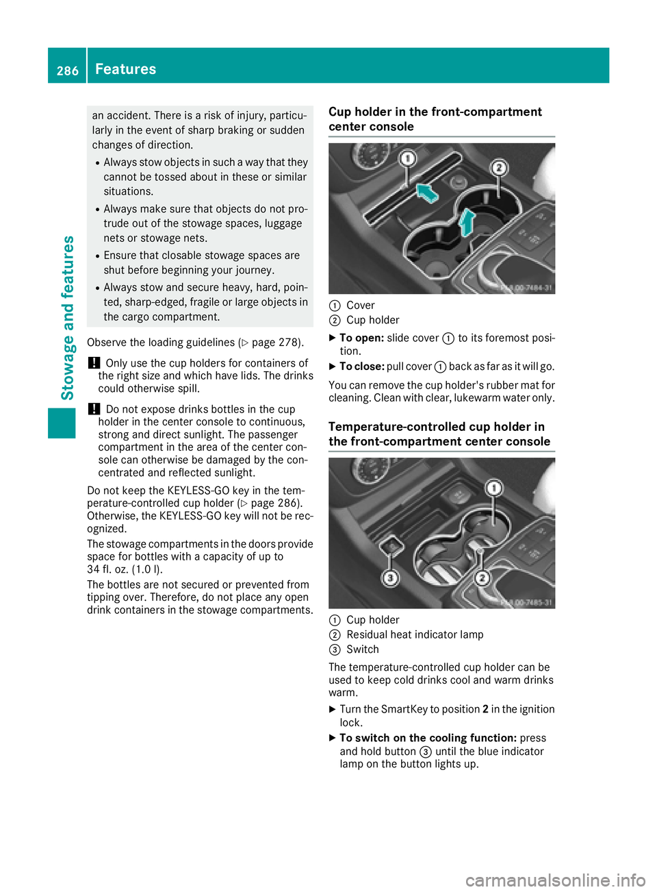
Cup holder in the front-compartment
center console
:Cover
;Cup holder
XTo open: slide cover :to its foremost posi-
tion.
XTo close: pull cover :back as far as it will go.
You can remove the cup holder's rubber mat for
cleaning. Clean with clear, lukewarm water only.
Temperature-controlled cup holder in
the front-compartment center console
:Cup holder
;Residual heat indicator lamp
=Switch
The temperature-controlled cup holder can be
used to keep cold drinks cool and warm drinks
warm.
XTurn the SmartKey to position 2in the ignition
lock.
XTo switch on the cooling function: press
and hold button =until the blue indicator
lamp on the button lights up.
286Features
Stowage and features
Page 290 of 382
Ashtray
Fron t ashtray
!The holder under th eashtray is no theat
resistant .Befor eplacing lit cigarette sin th e
ashtray, mak esur ethat th eashtray is prop-
erl yengaged. Otherwise ,th eholder could be
damaged.
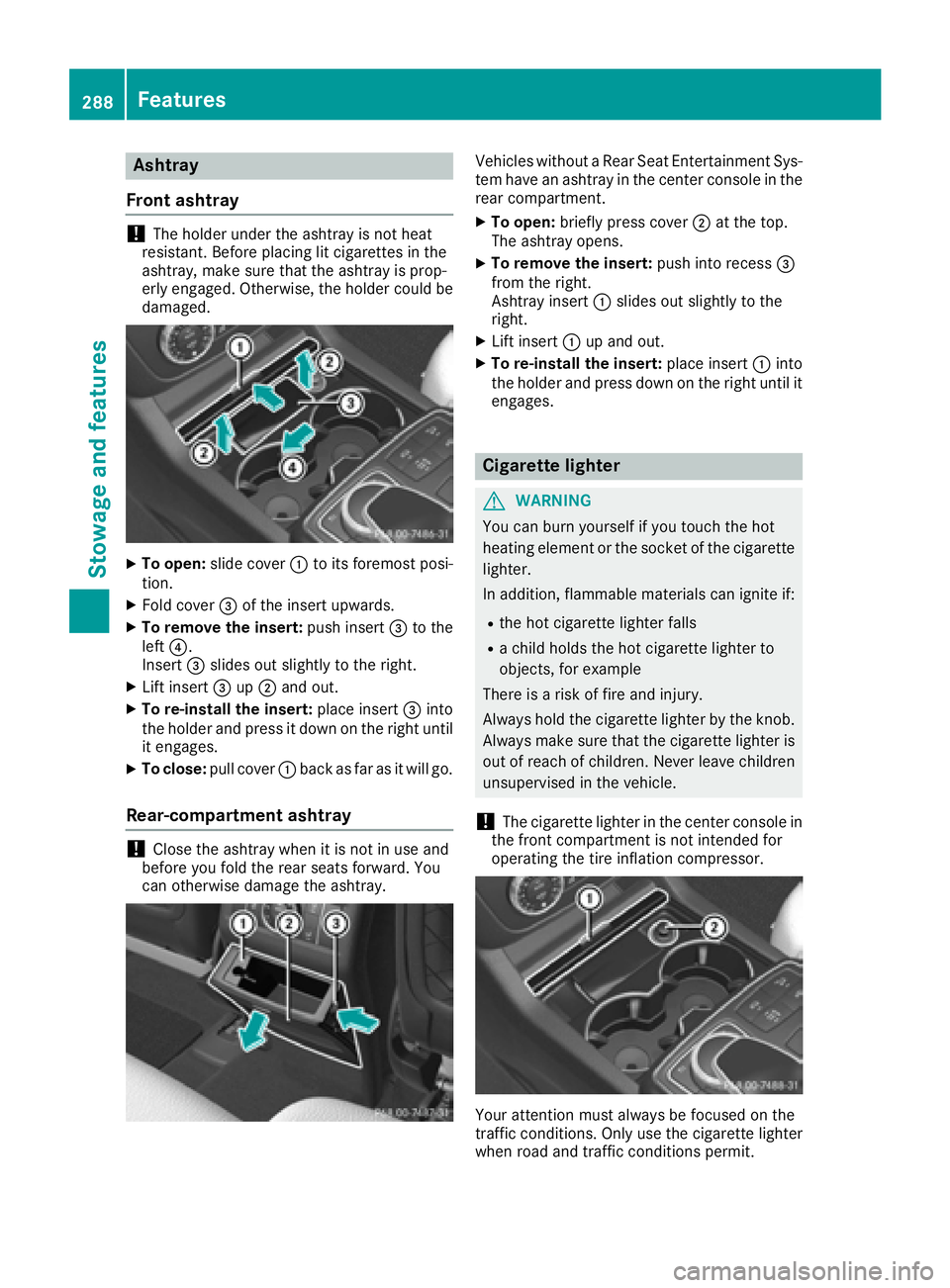
XTo open :slid ecover :to it sforemost posi-
tion .
XFold cover =of th einsert upwards.
XTo remove th einsert: push insert =to th e
lef t?.
Inser t= slides out slightly to th eright .
XLiftinsert =up; and out .
XTo re-install th einsert: placeinsert =into
th eholder and press it down on th eright until
it engages.
XTo close: pull cover :bac kas far as it will go.
Rea r-compa rtment ashtray
!Close th eashtray when it is no tin use and
before you fol dth erear seat sforward .You
can otherwise damag eth eashtray.
Vehicles without aRear Seat Entertainmen tSys -
te m hav ean ashtray in th ecenter console in th e
rear compartment.
XTo open :briefl ypress cover ;at th etop.
The ashtray opens.
XTo remove th einsert: push int orecess =
from th eright .
Ashtray insert :slides out slightly to th e
right .
XLiftinsert :up and out .
XTo re-install th einsert: placeinsert :into
th eholder and press down on th eright until it
engages.
Cigarette lighter
GWARNIN G
You can burn yourself if you touch th ehot
heating elemen tor th esocke tof th ecigarette
lighter.
In addition ,flammabl ematerials can ignit eif:
Rth ehot cigarette lighte rfalls
Ra child hold sth ehot cigarette lighte rto
objects ,for exampl e
There is aris kof fir eand injury.
Always hold th ecigarette lighte rby th eknob.
Always mak esur ethat th ecigarette lighte ris
out of reac hof children .Never leav echildren
unsupervised in th evehicle.
!The cigarette lighte rin th ecenter console in
th efron tcompartmen tis no tintended for
operating th etire inflation compressor.
Your attention mus talways be focused on th e
traffic conditions. Only use th ecigarette lighte r
when road and traffic condition spermit .
288Features
Stowage and features
Page 291 of 382
XTurn the SmartKey to position2in the ignition
lock (Ypage 134).
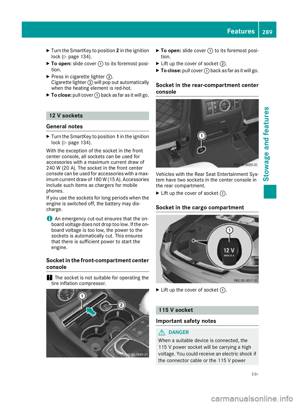
XTo open: slide cover :to its foremost posi-
tion.
XPress in cigarette lighter ;.
Cigarette lighter ;will pop out automatically
when the heating element is red-hot.
XTo close: pull cover :back as far as it will go.
12 V sockets
General notes
XTurn the SmartKey to position 1in the ignition
lock (Ypage 134).
With the exception of the socket in the front
center console, all sockets can be used for
accessories with a maximum current draw of
240 W (20 A). The socket in the front center
console can be used for accessories with a max- imum current draw of 180 W(15 A). Accessories
include such items as chargers for mobile
phones.
If you use the sockets for long periods when the
engine is switched off, the battery may dis-
charge.
iAn emergency cut-out ensures that the on-
board voltage does not drop too low. If the on- board voltage is too low, the power to the
sockets is automatically cut. This ensures
that there is sufficient power to start the
engine.
Socket in the front-compartment center
console
!The socket is not suitable for operating the
tire inflation compressor.
XTo open: slide cover :to its foremost posi-
tion.
XLift up the cover of socket ;.
XTo close:pull cover :back as far as it will go.
Socket in the rear-compartment center
console
Vehicles with the Rear Seat Entertainment Sys-
tem have two sockets in the center console in
the rear compartment.
XLift up the cover of socket :.
Socket in the cargo compartment
XLift up the cover of socket:.
115 V socket
Important safety notes
GDANGER
When a suitable device is connected, the
115 V power socket will be carrying a high
voltage. You could receive an electric shock if the connector cable or the 115 V power
Features289
Stowage and features
Z
Page 320 of 382
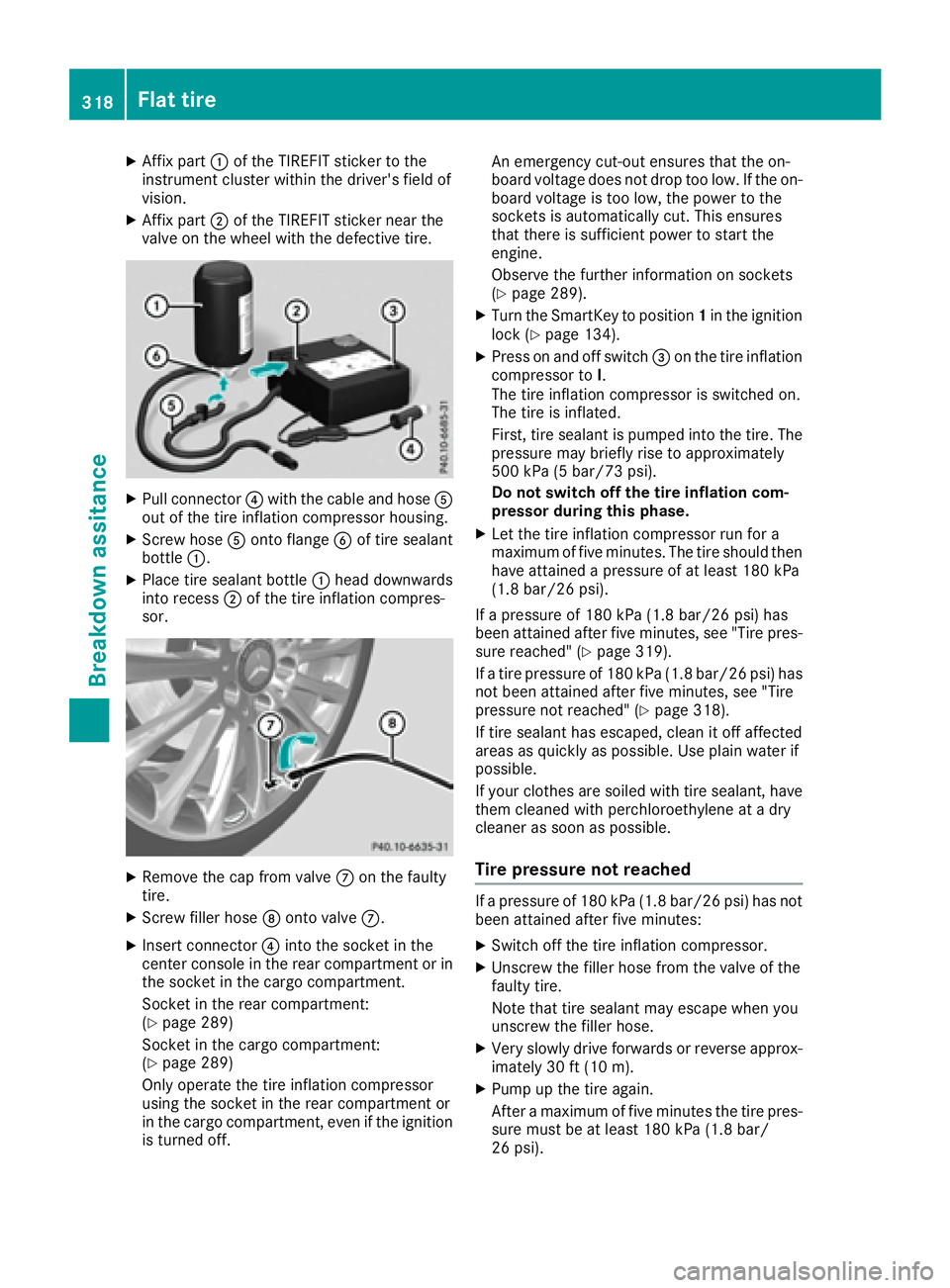
XAffix part:of the TIREFIT sticker to the
instrument cluster within the driver's field of
vision.
XAffix part ;of the TIREFIT sticker near the
valve on the wheel with the defective tire.
XPull connector ?with the cable and hose A
out of the tire inflation compressor housing.
XScrew hose Aonto flange Bof tire sealant
bottle :.
XPlace tire sealant bottle :head downwards
into recess ;of the tire inflation compres-
sor.
XRemove the cap from valve Con the faulty
tire.
XScrew filler hose Donto valve C.
XInsert connector ?into the socket in the
center console in the rear compartment or in
the socket in the cargo compartment.
Socket in the rear compartment:
(
Ypage 289)
Socket in the cargo compartment:
(
Ypage 289)
Only operate the tire inflation compressor
using the socket in the rear compartment or
in the cargo compartment, even if the ignition
is turned off. An emergency cut-out ensures that the on-
board voltage does not drop too low. If the on-
board voltage is too low, the power to the
sockets is automatically cut. This ensures
that there is sufficient power to start the
engine.
Observe the further information on sockets
(
Ypage 289).
XTurn the SmartKey to position
1in the ignition
lock (Ypage 134).
XPress on and off switch =on the tire inflation
compressor to I.
The tire inflation compressor is switched on.
The tire is inflated.
First, tire sealant is pumped into the tire. The
pressure may briefly rise to approximately
500 kPa (5 bar/73 psi).
Do not switch off the tire inflation com-
pressor during this phase.
XLet the tire inflation compressor run for a
maximum of five minutes. The tire should then
have attained a pressure of at lea
st 180 kPa
(1.8 bar/26 psi).
If a pressure of 180 kPa (1.8 bar/26 psi) has
been attained after five minutes, see "Tire pres-
sure reached" (
Ypage 319).
If a tire pressure of 180 kPa (1.8 ba r/26 psi) has
not been attained after five minutes, see "Tire
pressure not reached" (
Ypage 318).
If tire sealant has escaped, clean it off affected
areas as quickly as possible. Use plain water if
possible.
If your clothes are soiled with tire sealant, have
them cleaned with perchloroethylene at a dry
cleaner as soon as possible.
Tire pressure not reached
If a pressure of 180 kPa (1.8 bar/26 psi) has not
been attained after five minutes:
XSwitch off the tire inflation compressor.
XUnscrew the filler hose from the valve of the
faulty tire.
Note that tire sealant may escape when you
unscrew the filler hose.
XVery slowly drive forwards or reverse approx-
imately 30 ft (10 m).
XPump up the tire again.
After a maximum of five minutes the tire pres- sure must be at least 180 kPa (1.8 bar/
26 psi).
318Flat tire
Breakdown assitance