2016 MERCEDES-BENZ GLE-CLASS COUPE lights
[x] Cancel search: lightsPage 288 of 382
an accident. There is a risk of injury, particu-
larly in the event of sharp braking or sudden
changes of direction.
RAlways stow objects in such a way that theycannot be tossed about in these or similar
situations.
RAlways make sure that objects do not pro-
trude out of the stowage spaces, luggage
nets or stowage nets.
REnsure that closable stowage spaces are
shut before beginning your journey.
RAlways stow and secure heavy, hard, poin-
ted, sharp-edged, fragile or large objects in
the cargo compartment.
Observe the loading guidelines (
Ypage 278).
!Only use the cup holders for containers of
the right size and which have lids. The drinks
could otherwise spill.
!Do not expose drinks bottles in the cup
holder in the center console to continuous,
strong and direct sunlight. The passenger
compartment in the area of the center con-
sole can otherwise be damaged by the con-
centrated and reflected sunlight.
Do not keep the KEYLESS-GO key in the tem-
perature-controlled cup holder (
Ypage 286).
Otherwise, the KEYLESS-GO key will not be rec- ognized.
The stowage compartments in the doors provide
space for bottles with a capacity of up to
34 fl. oz. (1.0 l).
The bottles are not secured or prevented from
tipping over. Therefore, do not place any open
dr
ink containers in the stowage compartments.
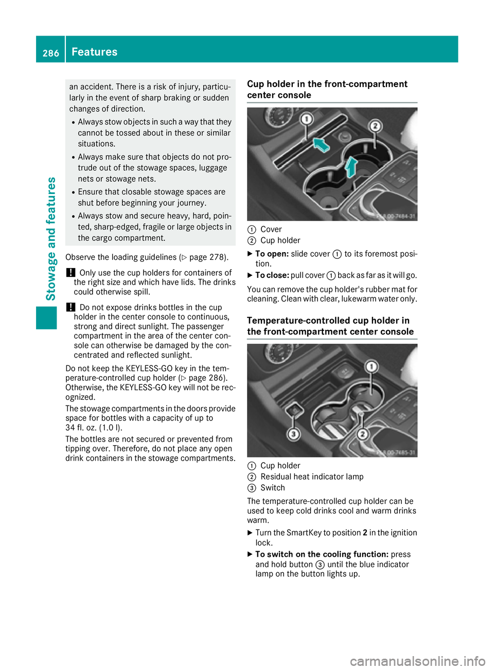
Cup holder in the front-compartment
center console
:Cover
;Cup holder
XTo open: slide cover :to its foremost posi-
tion.
XTo close: pull cover :back as far as it will go.
You can remove the cup holder's rubber mat for
cleaning. Clean with clear, lukewarm water only.
Temperature-controlled cup holder in
the front-compartment center console
:Cup holder
;Residual heat indicator lamp
=Switch
The temperature-controlled cup holder can be
used to keep cold drinks cool and warm drinks
warm.
XTurn the SmartKey to position 2in the ignition
lock.
XTo switch on the cooling function: press
and hold button =until the blue indicator
lamp on the button lights up.
286Features
Stowage and features
Page 289 of 382
XTo switch on the heating function:press
and hold button =until the red indicator
lamp on the button lights up.
XTo switch off the function: press and hold
button =until the indicator lamp on the but-
ton goes out.
When the heating function is used, the metal
insert of the cup holder is heated. Once a certain
temperature is reached, residual heat indicator
lamp ;lights up. This means that the metal
insert of the cup holder is hot. For this reason,
you must not reach into the cup holder metal
insert.
Do not use hard or sharp objects to clean the
cup holder. Use only a soft cloth to clean it.
Cup holder in the rear seat armrest
!Do not sit on or support your body weight on
the rear seat armrest when it is folded down,
as you could otherwise damage it.
XFold down the rear seat armrest.
Cup holder :is located in the rear seat arm-
rest.
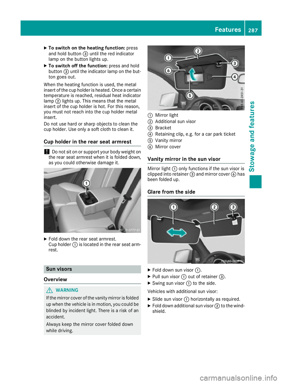
Sun visors
Overview
GWARNING
If the mirror cover of the vanity mirror is folded
up when the vehicle is in motion, you could be
blinded by incident light. There is a risk of an
accident.
Always keep the mirror cover folded down
while driving.
:Mirror light
;Additional sun visor
=Bracket
?Retaining clip, e.g. for a car park ticket
AVanity mirror
BMirror cover
Vanity mirror in the sun visor
Mirror light :only functions if the sun visor is
clipped into retainer =and mirror cover Bhas
been folded up.
Glare from the side
XFold down sun visor :.
XPull sun visor:out of retainer =.
XSwing sun visor :to the side.
Vehicles with additional sun visor:
XSlide sun visor :horizontally as required.
XFold down additional sun visor ;to the wind-
shield.
Features287
Stowag ean d features
Z
Page 292 of 382

socket is pulled out of the trim or is damaged
or wet. There is a risk of fatal injury.
RUse only connector cables that are dry and
free of damage.
RWhen the ignition is off, make sure that the
115 V power socket is dry.
RHave the 115 V power socket checked or
replaced immediately at a qualified speci-
alized workshop if it is damaged or has been
pulled out of the trim.
RNever plug the connector cable into a 115 V
power socket that is damaged or has been
pulled out of the trim.
GDANGER
If you reach into the power socket or plug
inappropriate devices into the power socket,
you could receive an electric shock. There is a
risk of fatal injury.
Only connect appropriate devices to the
power socket.
!Note that work and repairs on the 115 V
power socket should only be carried out by
qualified specialist personnel.
General notes
The 115 Vpower socket provides an alternating
voltage of 115 V so that small electronic devices
can be connected. These devices, such as
games consoles, chargers and laptops, must not consume more than a maximum of 150 watts
altogether.
Requirements for operation of these devices:
Rthe electronic device that you connect has a
suitable connector and conforms to stand-
ards specific to the country you are in.
Rthe plug of the electronic device is plugged
correctly into 115 V power socket.
Rthe maximum wattage of the device to be
connected must not exceed 150 watts.
Rthe on-board power supply is within a permis-
sible voltage range.
Rthe 12 V sockets in the rear compartment and
the cargo compartment are operational.
Using the 115 V power socket
XTo switch on: switch the ignition on.
XOpen flap=.
XInsert the plug of the electronic device into
115 V power socket :.
Indicator lamp ;lights up.
XTo switch off: disconnect the plug from
115 V power socket :.
Ensure that you do not pull on the cord.
290Features
Stowage and features
Page 301 of 382
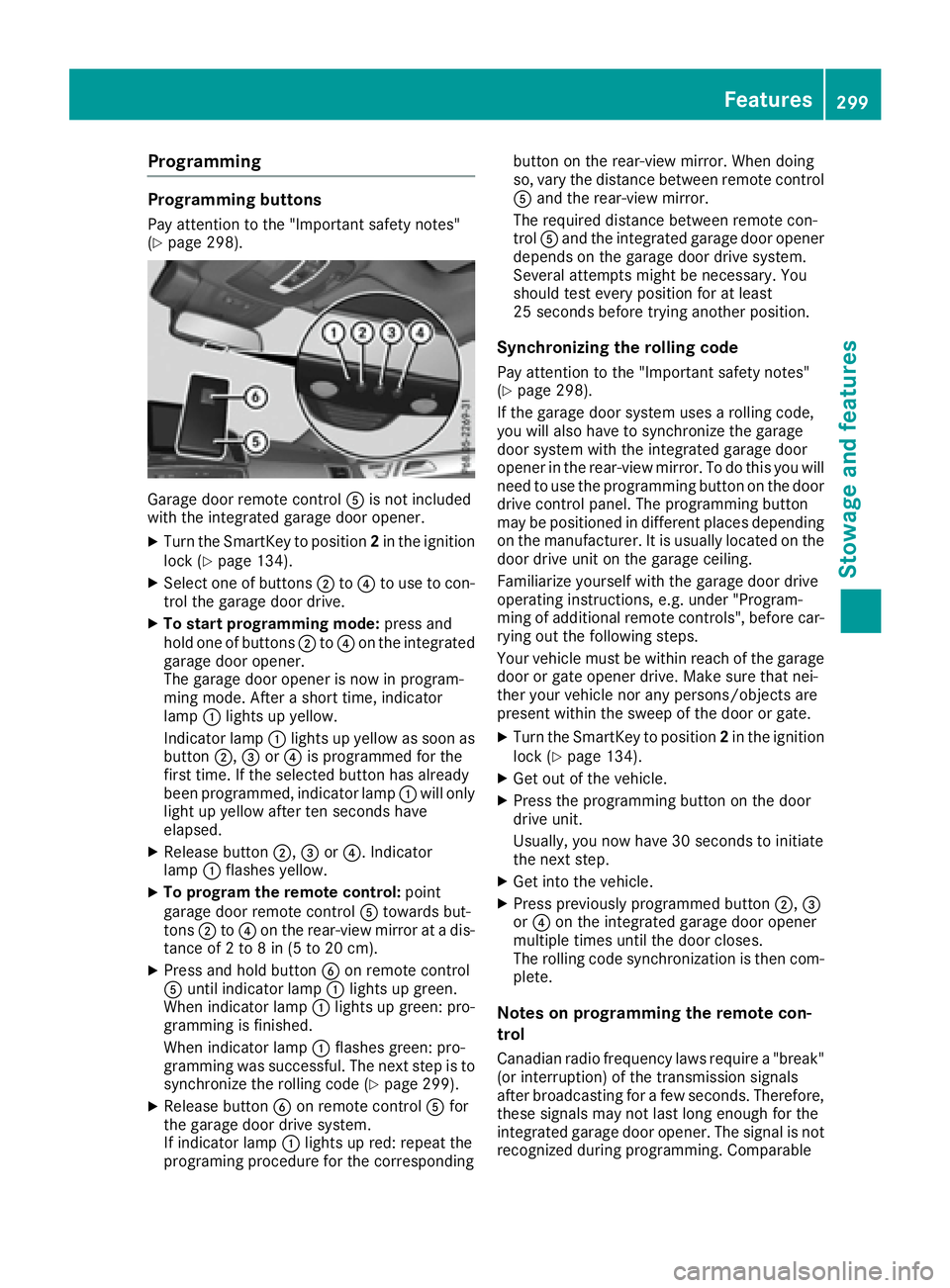
Programming
Programming buttons
Pay attention to the "Important safety notes"
(Ypage 298).
Garage door remote controlAis not included
with the integrated garage door opener.
XTurn the SmartKey to position 2in the ignition
lock (Ypage 134).
XSelect one of buttons ;to? to use to con-
trol the garage door drive.
XTo start programming mode: press and
hold one of buttons ;to? on the integrated
garage door opener.
The garage door opener is now in program-
ming mode. After a short time, indicator
lamp :lights up yellow.
Indicator lamp :lights up yellow as soon as
button ;,=or? is programmed for the
first time. If the selected button has already
been programmed, indicator lamp :will only
light up yellow after ten seconds have
elapsed.
XRelease button ;,=or?. Indicator
lamp :flashes yellow.
XTo program the remote control: point
garage door remote control Atowards but-
tons ;to? on the rear-view mirror at a dis-
tance of 2 to 8 in (5 to 20 cm).
XPress and hold button Bon remote control
A until indicator lamp :lights up green.
When indicator lamp :lights up green: pro-
gramming is finished.
When indicator lamp :flashes green: pro-
gramming was successful. The next step is to synchronize the rolling code (
Ypage 299).
XRelease button Bon remote control Afor
the garage door drive system.
If indicator lamp :lights up red: repeat the
programing procedure for the corresponding button on the rear-view mirror. When doing
so, vary the distance between remote control
A
and the rear-view mirror.
The required distance between remote con-
trol Aand the integrated garage door opener
depends on the garage door drive system.
Several attempts might be necessary. You
should test every position for at least
25 seconds before trying another position.
Synchronizing the rolling code
Pay attention to the "Important safety notes"
(Ypage 298).
If the garage door system uses a rolling code,
you will also have to synchronize the garage
door system with the integrated garage door
opener in the rear-view mirror. To do this you will
need to use the programming button on the door
drive control panel. The programming button
may be positioned in different places depending
on the manufact
urer. It is usually located on the
door drive unit on the garage ceiling.
Familiarize yourself with the garage door drive
operating instructions, e.g. under "Program-
ming of additional remote controls", before car-
rying out the following steps.
Your vehicle must be within reach of the garage
door or gate opener drive. Make sure that nei-
ther your vehicle nor any persons/objects are
present within the sweep of the door or gate.
XTurn the SmartKey to position 2in the ignition
lock (Ypage 134).
XGet out of the vehicle.
XPress the programming button on the door
drive unit.
Usually, you now have 30 seconds to initiate
the next step.
XGet into the vehicle.
XPress previously programmed button ;,=
or ? on the integrated garage door opener
multiple times until the door closes.
The rolling code synchronization is then com- plete.
Notes on programming the remote con-
trol
Canadian radio frequency laws require a "break"
(or interruption) of the transmission signals
after broadcasting for a few seconds. Therefore,
these signals may not last long enough for the
integrated garage door opener. The signal is not
recognized during programming. Comparable
Features299
Stowage and features
Z
Page 302 of 382
with Canadian law, some U.S. garage door open-
ers also feature a "break".
Proceed as follows:
Rif you live in Canada
Rif you have difficulties programming the
garage door opener (regardless of where you
live) when using the programming steps
XPress and hold one of buttons;to? on the
integrated garage door opener.
After a short time, indicator lamp :lights up
yellow.
XRelease the button.
Indicator lamp :flashes yellow.
XPress button Bof garage door remote con-
trol Afor two seconds, then release it for two
seconds.
XPress button Bagain for two seconds.
XRepeat this sequence on button Bof remote
control Auntil indicator lamp :lights up
green.
When indicator lamp :lights up green: pro-
gramming is finished.
When indicator lamp :flashes green: pro-
gramming was successful. The next step is to
synchronize the rolling code.
XRelease button Bof remote control Aof the
garage door drive.
If indicator lamp :lights up red: repeat the
programming process for the corresponding
button on the rear-view mirror. When doing
so, vary the distance between remote control
A and the rear-view mirror.
The required distance between remote con-
trol Aand the integrated garage door opener
depends on the garage door drive system.
Several attempts might be necessary. You
should test every position for at least
25 seconds before trying another position.
Problems when programming
If you are experiencing problems programing
th e integrated garage door opener on the rear-
view mirror, take note of the following instruc-
tions:
RCheck the transmitter frequency used by
garage door drive remote control Aand
whether it is supported. The transmitter fre-
quency can usually be found on the back of
the garage door drive remote control.
The integrated garage door opener is com-
patible with devices that have units which operate in the frequency range of 280 to
433 MHz.
RReplace the batteries in garage door remote
control
A. This increases the likelihood that
garage door remote control Awill transmit a
strong and precise signal to the integrated
garage door opener.
RWhen programming, hold remote control A
at varying distances and angles from the but-
ton which you are programming. Try various
angles at a distance between 2and 12 inches
(5to 30 cm) or at the same angle but at varying
distances.
RIf another remote control is available for the
same garage door drive, repeat the same pro-
gramming steps with this remote control.
Before performing these steps, make sure
that new batteries have been installed in
garage door drive remote control A.
RNote that some remote controls only transmit
for a limited amount of time (the indicator
lamp on the remote control goes out). Press
buttonBon remote control Aagain before
transmission ends.
RAlign the antenna cable of the garage door
open er unit. This can improve signal recep-
tion/transmission.
Opening/closing the garage door
After it has been programmed, the integrated
garage door opener performs the function of the
garage door system remote control. Please also
read the operating instructions for the garage
door system.
XTurn the SmartKey to position 2in the ignition
lock (Ypage 134).
XPress button ;,=or? which you have
programmed to operate the garage door.
Garage door system with a fixed code: indi-
cator lamp :lights up green.
Garage door system with a rolling code: indi-
cator lamp :flashes green.
The transmitter will transmit a signal as long
as the button is pressed. The transmission is
halted after a maximum of ten seconds and
indicator lamp :lights up yellow.
XPress button ;,=or? again if necessary.
300Features
Stowage and features
Page 303 of 382
Clearing the memory
Make sure that you clear the memory of the
integrated garage door opener before selling the
vehicle.
XTurn the SmartKey to position2in the ignition
lock (Ypage 134).
XPress and hold buttons ;and ?.
The indicator lamp initially lights up yellow
and then green.
XRelease buttons ;and ?.
The memory of the integrated garage door
opener in the rear-view mirror is cleared.
Floormats
GWARNING
Objects in the driver's footwell can restrict the pedal travel or obstruct a depressed pedal.
The operating and road safety of the vehicle is
jeopardized. There is a risk of an accident.
Make sure that all objects in the vehicle are
stowed correctly, and that they cannot enter
the driver's footwell. Install the floormats
securely and as specified in order to ensure
sufficient clearance for the pedals. Do not use
loose floormats and do not place floormats on
top of one another.
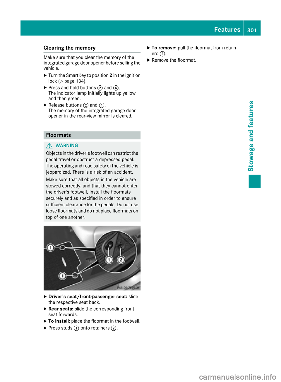
XDriver's seat/front-passenger seat: slide
the respective seat back.
XRear seats: slide the corresponding front
seat forwards.
XTo install: place the floormat in the footwell.
XPress studs :onto retainers ;.
XTo remove:pull the floormat from retain-
ers ;.
XRemove the floormat.
Features301
Stowage and features
Z
Page 311 of 382
Power washers
GWARNING
The water jet from a circular jet nozzle (dirt
blasters) can cause invisible exterior damage
to the tires or chassis components. Compo-
nents damaged in this way may fail unexpect-
edly. There is a risk of an accident.
Do not use power washers with circular jet
nozzles to clean the vehicle. Have damaged
tires or chassis components replaced imme-
diately.
!Always maintain a distance of at least
11.8 in (30 cm) between the vehicle and the
power washer nozzle. Information about the
correct distance is available from the equip-
ment manufacturer.
Move the power washer nozzle around when
cleaning your vehicle.
Do not aim directly at any of the following:
Rtires
Rdoor gaps, roof gaps, joints, etc.
Relectrical components
Rbattery
Rconnectors
Rlights
Rseals
Rtrim
Rventilation slots
Damaged seals or electrical components can
lead to leaks or failures.
Cleaning the paintwork
!Do not affix:
Rstickers
Rfilms
Rmagnetic plates or similar items
to painted surfaces. You could otherwise
damage the paintwork.
Scratches, corrosive deposits, areas affected by
corrosion and damage caused by inadequate
care cannot always be completely repaired. In
such cases, visit a qualified specialist workshop.
XRemove dirt immediately, where possible,
while avoiding rubbing too hard.
XSoak insect remains with insect remover and
rinse off the treated areas afterwards.
XSoak bird droppings with water and rinse off
the treated areas afterwards.
XRemove coolant, brake fluid, tree resin, oils,
fuels and greases by rubbing gently with a
cloth soaked in petroleum ether or lighter
fluid.
XUse tar remover to remove tar stains.
XUse silicone remover to remove wax.
If water no longer forms "beads" on the paint
surface, use the paint care products recommen-
ded and approved by Mercedes-Benz. This is the
case approximately every three to five months,
depending on the climate conditions and the
care product used.
If dirt has penetrated the paint surface or if the
paint has become dull, the paint cleaner recom-
mended and approved by Mercedes-Benz
should be used.
Do not use these care products in the sun or on
the hood while the hood is hot.
XUse a suitable touch-up stick, e.g. MB Touch-
Up Stick, to repair slight damage to the paint-
work quickly and provisionally.
Matte finish care
!Never polish the vehicle or the light alloy
wheels. Polishing causes the finish to shine.
!The following may cause the paint to
become shiny and thus reduce the matte
effect:
Rstrong rubbing of the paintwork with
unsuitable materials
Rfrequent use of automatic car washes
Rwashing the vehicle in direct sunlight
!Never use paint cleaner, buffing or polishing
products, or gloss preserver, e.g. wax. These
products are only suitable for high-gloss sur-
faces. Their use on vehicles with matte finish
leads to considerable surface damage (shiny,
mottled areas).
Always have paintwork repairs carried out at a
qualified specialist workshop.
!Do not use wash programs with a hot wax
treatment under any circumstances.
Care309
Maintenance and care
Z
Page 341 of 382

halt by braking carefully. Avoid abrupt steering
movements.
The tire pressure monitor has a yellow warning
lamp in the instrument cluster for indicating
pressure loss or a malfunction. Whether the
warning lamp flashes or lights up indicates
whether a tire pressure is too low or the tire
pressure monitor is malfunctioning:
Rif the warning lamp is lit continuously, the tire
pressure on one or more tires is significantly
too low. The tire pressure monitor is not mal-functioning.
Rif the warning lamp flashes for around a
minute and then remains lit constantly, the
tire pressure monitor is malfunctioning.
In addition to the warning lamp, a message
appears in the multifunction display. Observe
the information on display messages
(
Ypage 259).
It may take up to ten minutes for a malfunction of the tire pressure monitor to be indicated. A
malfunction will be indicated by the tire pres-
sure warning lamp flashing for approximately
one minute and then remaining lit. When the
malfunction has been rectified, the tire pressure
warning lamp goes out after a few minutes of
driving.
The tire pressure values indicated by the on-
board computer may differ from those meas-
ured at a gas station with a pressure gauge. The
tire pressures shown by the on-board computer
refer to those measured at sea level. At high
altitudes, the tire pressure values indicated by a
pressure gauge are higher than those shown by the on-board computer. In this case, do not
reduce the tire pressures.
The operation of the tire pressure monitor can
be affected by interference from radio transmit-
ting equipment (e.g. radio headphones, two-way
radios) that may be being operated in or near the vehicle.
Checking the tire pressure electroni-
cally
XMake sure that the SmartKey is in position 2
in the ignition lock (Ypage 134).
XPress the =or; button on the steering
wheel to select the Serv.menu.
XPress the9or: button to select
Tire Pressure.
XPress the abutton.
The current tire pressure of each tire is shown
in the multifunction display.
If the vehicle has been parked for longer than
20 minutes, the Tire pressure will be
displayed after driving a few minutesmessage appears.
After a teach-in process, the tire pressure mon-
itor automatically detects new wheels or new
sensors. As long as a clear allocation of the tire
pressure value to the individual wheels is not
possible, theTire
PressureMonitorActivedisplay message is shown instead of the tire
pressure display. The tire pressures are already
being monitored.
iIf an emergency spare wheel is mounted,
the system may continue to show the tire
pressure of the wheel that has been removed
for a few minutes. If this occurs, note that the
value displayed for the position where the
spare wheel is mounted is not the same as the
current tire pressure of the emergency spare
wheel.
Tire pressure monitor warning mes-
sages
If the tire pressure monitor detects a pressure
loss in one or more tires, a warning message is
shown in the multifunction display. The yellow
tire pressure warning lamp then lights up.
RIf the Please Correct Tire Pressuremessage appears in the multifunction display,
the tire pressure in at least one tire is too low.
The tire pressure must be corrected when the
opportunity arises.
RIf the Check Tiresmessage appears in the
multifunction display, the tire pressure in at
least one tire has dropped significantly. The
tires must be checked.
RIf the WarningTireMalfunctionmessage
appears in the multifunction display, the tire
pressure in at least one tire has dropped sud-
denly. The tires must be checked.
If the wheel positions on the vehicle are rotated, the tire pressures may be displayed for the
wrong positions for a short time. This is rectified
after a few minutes of driving, and the tire pres-
sures are displayed for the correct positions.
Tire pressure339
Wheels and tires
Z