2016 MERCEDES-BENZ E-SEDAN steering wheel
[x] Cancel search: steering wheelPage 257 of 350
If a mobile phone network and GPS reception
are available, the system transfers data to the
Mercedes-Benz Customer Assistance Center,
for example:
Rcurrent location of the vehicle
Rvehicle identification number
The COMAND/Audio 20 display indicates
that a call is active. During the call, you can
change to the navigation menu by pressing
the NAVI button in COMAND/Audio 20, for
example.
Voice output is not available in this case.
A voice connection is established between
the Mercedes-Benz Customer Assistance
Center and the vehicle occupants.
From the remote malfunction diagnosis, the
Mercedes-Benz Customer Assistance Center
can ascertain the nature of the problem. In
the Digital Operator's Manual, you will find
information on remote malfunction diagno-
sis.
The Mercedes-Benz Customer Assistance
Center either sends a qualified Mercedes-
Benz technician or makes arrangements for
your vehicle to be transported to the nearest
authorized Mercedes-Benz Center.
You may be charged for services such as
repair work and/or towing.
You can find more information in the separate
mbrace manual.
The system has not been able to initiate a
Roadside Assistance call, if:
Rthe indicator lamp for Roadside Assistance
call button Fis flashing continuously.
Rno voice connection to the Mercedes-Benz
Customer Assistance Center was estab-
lished.
This can occur if the relevant mobile phone
network is not available, for example.
The Call Failed
message appears in the
multifunction display.
XTo end a call: press the~button on the
multifunction steering wheel.
or
XPress the corresponding COMAND/Audio
20 button for ending a phone call.
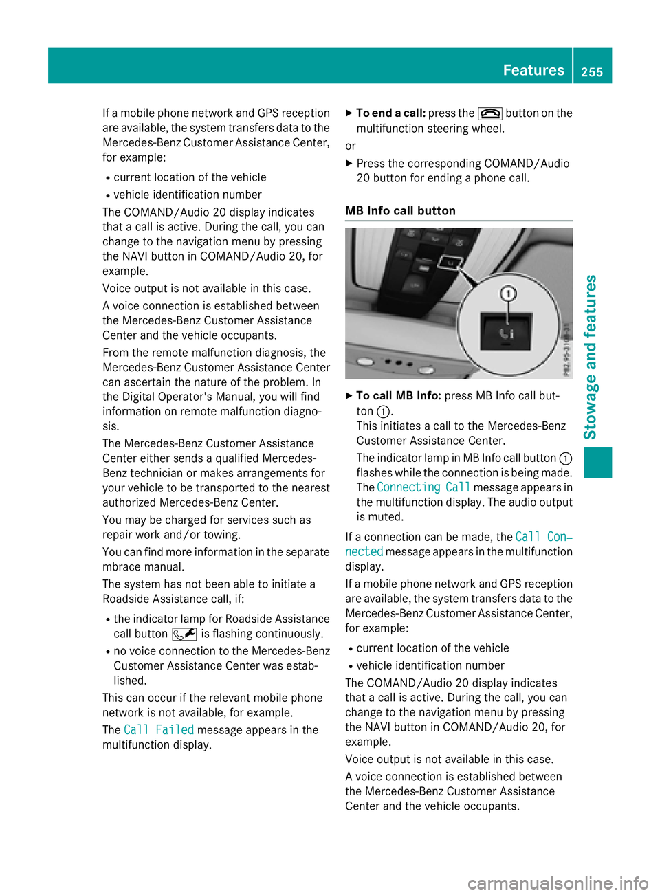
MB Info call button
XTo call MB Info: press MB Info call but-
ton :.
This initiates a call to the Mercedes-Benz
Customer Assistance Center.
The indicator lamp in MB Info call button :
flashes while the connection is being made.
The Connecting
Callmessage appears in
the multifunction display. The audio output
is muted.
If a connection can be made, the Call Con‐
nectedmessage appears in the multifunction
display.
If a mobile phone network and GPS reception
are available, the system transfers data to the
Mercedes-Benz Customer Assistance Center,
for example:
Rcurrent location of the vehicle
Rvehicle identification number
The COMAND/Audio 20 display indicates
that a call is active. During the call, you can
change to the navigation menu by pressing
the NAVI button in COMAND/Audio 20, for
example.
Voice output is not available in this case.
A voice connection is established between
the Mercedes-Benz Customer Assistance
Center and the vehicle occupants.
Features255
Stowage and features
Z
Page 258 of 350
You receive information about operating your
vehicle, about the nearest authorized
Mercedes-Benz Center and about other prod-
ucts and services from Mercedes-Benz.
You can find further information on the
mbrace system under "Owners Online" at
http://www.mbusa.com.
The system has not been able to initiate an
MB Info call, if:
Rthe indicator lamp in MB Info call button
ïis flashing continuously.
Rno voice connection to the Mercedes-Benz
Customer Assistance Center was estab-
lished.
This can occur if the relevant mobile phone
network is not available, for example.
The Call Failed
message appears in the
multifunction display.
XTo end a call: press the~button on the
multifunction steering wheel.
or
XPress the corresponding COMAND/Audio
20 button for ending a phone call.
Call priority
When service calls are active, e.g. Roadside
Assistance or MB Info calls, an emergency
call can still be initiated. In this case, an emer-
gency call will take priority and override all
other active calls.
The indicator lamp of the respective button
flashes until the call is ended.
An emergency call can only be terminated by the Mercedes-Benz Customer Assistance
Center.
All other calls can be ended by pressing:
Rthe ~ button on the multifunction steer-
ing wheel
Rthe corresponding button in COMAND/
Audio 20 to end the voice call
When a call is initiated, the audio system is
muted. The mobile phone is no longer connected to
COMAND/Audio 20.
However, if you want to use your mobile
phone, do so only when the vehicle is station-
ary and in a safe location.
Garage door opener
General notes
The HomeLink®garage door opener integra-
ted in the rear-view mirror allows you to oper-
ate up to three different door and gate sys-
tems.
Use the integrated garage door opener only
on garage doors that:
Rhave safety stop and reverse features and
Rmeet current U.S. federal safety standards
Once programed, the integrated garage door
opener in the rear-view mirror will assume the
function of the garage door system's remote
control. Please also read the operating
instructions for the garage door system.
When programming a garage door opener,
park the vehicle outside the garage. Do not
run the engine while programming.
Certain garage door drives are incompatible
with the integrated garage door opener. If you
have difficulty programing the integrated
garage door opener, contact an authorized
Mercedes-Benz Center.
Alternatively, you can call the following tele-
phone assistance services:
RUSA: Mercedes-Benz Customer Assistance
Center at 1-800-FOR-MERCedes
RCanada: Customer Service at
1-800-387-0100
RHomeLink®hotline 1-800-355-3515 (free
of charge)
More information on HomeLink
®and/or
compatible products is also available online
at http://www.homelink.com.
Notes on the declaration of conformity
(
Ypage 31).
256Features
Stowage and features
Page 270 of 350
wiping noises caused by residue on the wind-
shield.
Information in the Digital Operator's
Manual
In the Digital Operator's Manual you will find
information on the following topics:
RWashing by hand
RPower washers
RCleaning the paintwork
RMatte finish care
RCleaning the wheels
RCleaning the windows
RCleaning wiper blades
RCleaning the exterior lighting
RCleaning the mirror turn signals
RCleaning the sensors
RCleaning the rear view camera
RCleaning the 360° camera
RCleaning the exhaust pipes
Interior care
In the Digital Operator's Manual you will find
information on the following topics:
RCleaning the display
RCleaning the plastic trim
RCleaning the steering wheel and gear or
selector lever
RCleaning genuine wood and trim strips
RCleaning the seat covers
RCleaning the seat belts
RCleaning the headliner and carpets
268Care
Maintenance and care
Page 274 of 350
MOExtended tires (tires with run-flat
properties)
General notes
With MOExtended tires (tires with run flat
characteristics), you can continue to drive
your vehicle even if there is a total loss of
pressure in one or more tires. The affected
tire must not show any clearly visible damage.
You can recognize MOExtended tires by the
MOExtended marking which appears on the
sidewall of the tire. You will find this marking next to the tire size designation, the load-
bearing capacity and the speed index
(
Ypage 303).
MOExtended tires may only be used in con-
junction with an active tire pressure monitor.
If a pressure loss warning message
appears in the multifunction display:
Robserve the instructions in the display mes-
sages (
Ypage 200).
Rcheck the tire for damage.
Rif driving on, observe the following notes.
The driving distance possible in run-flat mode
is approximately 50 miles (80 km) when the
vehicle is partially laden and approximately
18 miles (30 km) when the vehicle is fully
laden.
In addition to the vehicle load, the driving dis-
tance possible depends upon:
Rvehicle speed
Rroad condition
Routside temperature
The driving distance possible in run-flat mode
may be reduced by extreme driving condi-
tions/maneuvers, or it can be increased
through a moderate style of driving.
The driving distance possible in run-flat mode
is counted from the moment the tire pressure
loss warning appears in the multifunction dis-
play.
You must not exceed a maximum speed of
50 mph (80 km/h). When replacing one or all tires, please
observe the following specifications for your
vehicle's tires:
Rsize
Rthe type and
Rthe "MOExtended" mark
If a tire has gone flat and cannot be replaced
with a MOExtended tire, a standard tire may
be used as a temporary measure. Make sure
that you use the proper size a
nd type (sum-
mer or winter tire).
Vehicles equipped with MOExtended tires are
not equipped with a TIREFIT kit at the factory.
It is therefore recommended that you addi-
tionally equip your vehicle with a TIREFIT kit if you mount tires that do not feature run-flat
properties, e.g. winter tires. A TIREFIT kit may
be obtained from a qualified specialist work-
shop.
Important safety notes
GWARNING
When driving in emergency mode, the driving
characteristics deteriorate, e.g. when corner-
ing, accelerating quickly and when braking.
There is a risk of an accident.
Do not exceed the stated maximum speed.
Avoid abrupt steering and driving maneuvers,
and driving over obstacles (curbs, potholes,
off-road). This applies in particular to a laden
vehicle.
Stop driving in emergency mode if:
Ryou hear banging noises.
Rthe vehicle starts to shake.
Ryou see smoke and smell rubber.
RESP®is intervening constantly.
Rthere are tears in the sidewalls of the tire.
After driving in emergency mode, have the
wheel rims checked at a qualified specialist
workshop with regard to their further use. The
defective tire must be replaced in every case.
272Flat tire
Roadside Assistance
Page 285 of 350
XTake cover:off the opening.
XScrew in the towing eye clockwise as far as
it will go and tighten it.
Removing the towing eye
XUnscrew and remove the towing eye.
XAttach cover :to the bumper and press
until it engages.
XPlace the towing eye in the vehicle tool kit.
Towing a vehicle with both axles on
the ground
It is important that you observe the safety
instructions when towing away your vehicle
(
Ypage 281).
The automatic transmission automatically
shifts to position Pwhen you open the driver's
or front-passenger door or when you remove
the SmartKey from the ignition lock. In order
to ensure that the automatic transmission
stays in position Nwhen towing the vehicle,
you must observe the following points:
XMake sure that the vehicle is stationary and
the SmartKey in the ignition lock is in posi- tion 0.
XTurn the SmartKey to position 2in the igni-
tion lock.
On vehicles with KEYLESS-GO, use the
SmartKey instead of the Start/Stop button
(
Ypage 139).
XDepress and hold the brake pedal.
XShift the automatic transmission to posi-
tion N.
XRelease the brake pedal.
XRelease the parking brake.
XSwitch on the hazard warning lamps, see
the Digital Operator's Manual.
XLeave the SmartKey in position 2in the
ignition lock.
iWhen towing with the hazard warning
lamps switched on, use the combination
switch as usual to signal a change of direc- tion. In this case, only the indicator lamps
for the direction of travel flash. After reset-
ting the combination switch, the hazard
warning lamp starts flashing again.
Towing the vehicle with the rear axle
raised
!
Vehicles with 4MATIC must not be towed
with either the front or the rear axle raised,
as doing so will damage the transmission.
!Vehicles with automatic transmission
must not be towed with the rear axle raised.
The vehicle/trailer combination may oth-
erwise swerve or even roll over.
!The ignition must be switched off if you
are towing the vehicle with the rear axle
raised. Intervention by ESP
®could other-
wise damage the brake system.
Transporting the vehicle
!
You may only secure the vehicle by the
wheels, not by parts of the vehicle such as
axle or steering components. Otherwise,
the vehicle could be damaged.
The towing eye can be used to pull the vehicle
onto a trailer or transporter for transporting
purposes.
XTurn the SmartKey to position 2in the igni-
tion lock.
XShift the automatic transmission to posi-
tion N.
As soon as the vehicle has been loaded:
XPrevent the vehicle from rolling away by
applying the parking brake.
XShift the automatic transmission to posi-
tion P.
XTurn the SmartKey to position 0in the igni-
tion lock and remove the SmartKey from
the ignition lock.
XSecure the vehicle.
Towing and tow-starting283
Roadside Assistance
Z
Page 297 of 350
For information on the message display, refer
to the "Checking the tire pressure electroni-
cally" section (
Ypage 296).
Important safety notes
GWARNING
Each tire, including the spare (if provided),
should be checked at least once every two
weeks when cold and inflated to the pressure recommended by the vehicle manufacturer
on the Tire and Loading Information placard
on the driver's door B-pillar or the tire pres-
sure label on the inside of the fuel filler flap. If
your vehicle has tires of a different size than
the size indicated on the Tire and Loading
Information placard or, if available, the tire
pressure label, you should determine the
proper tire pressure for those tires.
As an added safety feature, your vehicle has
been equipped with a tire pressure monitoring
system (TPMS) that illuminates a low tire pres-
sure telltale when one or more of your tires
are significantly underinflated. Accordingly,
when the low tire pressure telltale lights up,
you should stop and check your tires as soon
as possible, and inflate them to the proper
pressure. Driving on a significantly underin-
flated tire causes the tire to overheat and can
lead to tire failure.
Underinflation also reduces fuel efficiency
and tire tread life, and may affect the vehicle's
handling and stopping ability. Please note thatthe TPMS is not a substitute for proper tire
maintenance, and it is the driver's responsi-
bility to maintain correct tire pressure, even if
underinflation has not reached the level to
trigg er i
llumination of the TPMS low tire pres-
sure telltale.
Your vehicle has also been equipped with a
TPMS malfunction indicator to indicate when
the system is not operating properly. The
TPMS malfunction indicator is combined with
the low tire pressure telltale. When the sys-
tem detects a malfunction, the warning lamp
will flash for approximately a minute and then remain continuously illuminated. This
sequence will be repeated every time the vehi-
cle is started as long as the malfunction
exists. When the malfunction indicator is illu-
minated, the system may not be able to detect
or signal low tire pressure as intended.
TPMS malfunctions may occur for a variety of
reasons, including the installation of incom-
patible replacement or alternate tires or
wheels on the vehicle that prevent the TPMS
from functioning properly. Always check the
TPMS malfunction telltale after replacing one
or more tires or wheels on your vehicle to
ensure that the replacement or alternate Tires
and wheels allow the TPMS to continue to
function properly.
It is the driver's responsibility to set the tire
pressure to that recommended for cold tires
which is suitable for the operating situation
(
Ypage 291). Note that the correct tire pres-
sure for the current operating situation must
first be taught-in to the tire pressure monitor.
If there is a substantial loss of pressure, the
warning threshold for the warning message is
aligned to the reference values taught-in.
Restart the tire pressure monitor after adjust-
ing the pressure of the cold tires
(
Ypage 297). The current pressures are
saved as new reference values. As a result, a
warning message will appear if the tire pres-
sure drops significantly.
The tire pressure monitor does not warn you
of an incorrectly set ti
re pressure. Observe
the notes on the recommended tire pressure (
Ypage 291).
The tire pressure monitor is not able to warn
you of a sudden loss of pressure, e.g. if the
tire is penetrated by a foreign object. In the
event of a sudden loss of pressure, bring the
vehicle to a halt by braking carefully. Avoid
abrupt steering maneuvers.
Tire pressure295
Wheels and tires
Z
Page 300 of 350
Loading the vehicle
Instruction labels for tires and loads
GWARNING
Overloaded tires can overheat, causing a
blowout. Overloaded tires can also impair the steering and driving characteristics and lead
to brake failure. There is a risk of accident.
Observe the load rating of the tires. The load
rating must be at least half of the GAWR of
your vehicle. Never overload the tires by
exceeding the maximum load.
Two instruction labels on your vehicle show
the maximum possible load.
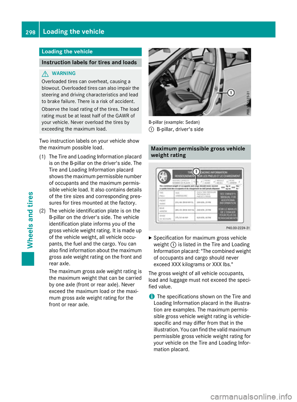
(1) The Tire and Loading Information placard is on the B-pillar on the driver's side. The
Tire and Loading Information placard
shows the maximum permissible number
of occupants and the maximum permis-
sible vehicle load. It also contains details
of the tire sizes and corresponding pres-
sures for tires mounted at the factory.
(2) The vehicle identification plate is on the B-pillar on the driver's side. The vehicle
identification plate informs you of the
gross vehicle weight rating. It is made up
of the vehicle weight, all vehicle occu-
pants, the fuel and the cargo. You can
also find information about the maximum
gross axle weight rating on the front and
rear axle.
The maximum gross axle weight rating is
the maximum weight that can be carried
by one axle (front or rear axle). Never
exceed the maximum load or the maxi-
mum gross axle weight rating for the
front or rear axle.
B-pillar (example: Sedan)
:
B-pillar, driver's side
Maximum permissible gross vehicle
weight rating
XSpecification for maximum gross vehicle
weight :is listed in the Tire and Loading
Information placard: "The combined weight of occupants and cargo should never
exceed XXX kilograms or XXX lbs."
The gross weight of all vehicle occupants,
load and luggage must not exceed the speci-
fied value.
iThe specifications shown on the Tire and
Loading Information placard in the illustra-
tion are examples. The maximum permis-
sible gross vehicle weight rating is vehicle- specific and may differ from that in the
illustration. You can find the valid maximum
permissible gross vehicle weight rating for
your vehicle on the Tire and Loading Infor-
mation placard.
298Loading the vehicle
Wheels and tires