2016 MERCEDES-BENZ E-SEDAN service
[x] Cancel search: servicePage 236 of 350
The access data for the mobile phone net-
work provider is selected once for the mobile
phone connected and is loaded again each
time the mobile phone is connected.
You must set the access data of the mobile
phone network provider who provides the
SIM card and the associated data package
(access settings) for the connected mobile
phone. The access data remains the same
when you are in a different country (roaming).
The access data of another network isnot
selected.
Setting access data
Set the access data in accordance with your
data package. You can contact your mobile
phone network provider to obtain the precise
access data.
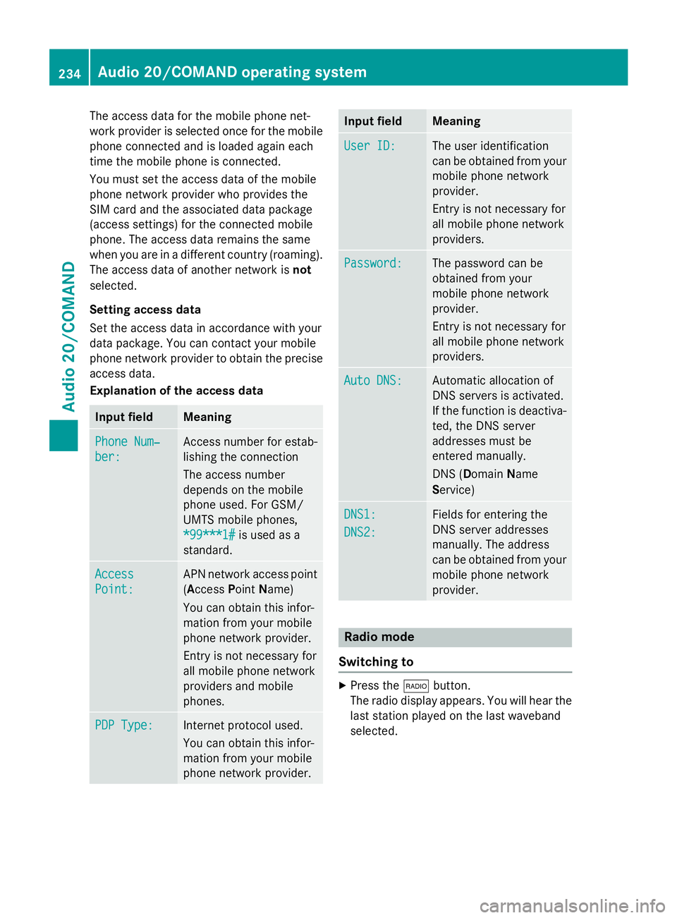
Explanation of the access data
Input fieldMeaning
Phone Num‐
ber:
Access number for estab-
lishing the connection
The access number
depends on the mobile
phone used. For GSM/
UMTS mobile phones,
*99***1#
is used as a
standard.
Access
Point:
APN network access point
(Access PointName)
You can obtain this infor-
mation from your mobile
phone network provider.
Entry is not necessary for
all mobile phone network
providers and mobile
phones.
PDP Type:Internet protocol used.
You can obtain this infor-
mation from your mobile
phone network provider.
Input fieldMeaning
User ID:The user identification
can be obtained from your
mobile phone network
provider.
Entry is not necessary for
all mobile phone network
providers.
Password:The password can be
obtained from your
mobile phone network
provider.
Entry is not necessary for
all mobile phone network
providers.
Auto DNS:Automatic allocation of
DNS servers is activated.
If the function is deactiva-
ted, the DNS server
addresses must be
entered manually.
DNS ( Domain Name
Service)
DNS1:
DNS2:
Fields for entering the
DNS server addresses
manually. The address
can be obtained from your
mobile phone network
provider.
Radio mode
Switching to
XPress the $button.
The radio display appears. You will hear the
last station played on the last waveband
selected.
234Audio 20/COMAND operating system
Audio 20/COMAND
Page 254 of 350
Information in the Digital Operator's
Manual
Inthe Digital Operator's Manual you willfind
information on the following topics:
RVanit y mirror inthe sun visor
RGlare from the side
mbrace
Information in the Digital Operator's
Manual
In the Digital Operator's Manual you willfind
information on the following topics:
RDownloading destinations inCOMAND
RSe arch & Send
RVehicle remote opening
RVehicle remote closing
RStolen vehicle recovery service
RVehicle remote malfunction diagnosis
RDownloading routes
RSp eed alert
RGeo fencing
RTriggering the vehicle alarm
iThe mbrace system isonly availab le inthe
USA.
General notes
The mbrace system is only availablein the
USA.
You must have a license agreement to acti-
vate the mbrace service. Make sure that your system isactivated and operational. To log in,
press the ïMBInfo call button. Ifany of
the steps mentioned are not carried out, the
system may not be activated.
If you have questions about the activation,
contact one of the fol lowing telephone hot-
lin es:
Mercedes-Benz Customer Assistance Center
at 1-800-FOR-M ERCedes (1-800-367-6372)
or 1-866-990-9007 Sh
ort lyafter successfully registering with the
mbrace service, a user IDand password will
be sent to you bymail. You can use th ispass-
word to log onto the mbrace area under "Own-
ers Onlin e" athttp://www.mbusa.com .
The system isavailab leif:
Rit has been activated and isoperational
Rthe corresponding mob ilephone network is
availab lefor transmitting data to the Cus-
tomer Center
Ra servic e subscr iption isavailab le
Rthe starter battery issufficiently charged
Determining the location of the vehicle on a
map isonly possible if:
RGPS reception isavailable.
Rthe vehicle posit ion canbeforwarded to
the Customer Assistance Center.
The mbrace system
To adjust the volume during a call, proceed as
follows:
XPress the WorX button on the mul-
tifunction steering wheel.
or
XUse the COMAND/A udio 20 volume con-
trol.
The system offers various servic es, e.g.:
RAutomaticand manual emergency call
RRoadside Assistance call
RMB Info call
You can find information and a description of
all availab lefeatures under "Owners Online"
at http:/ /www.mbusa.com.
System self-test
After you have switched on the ignit ion, the
system carries out a self-diagnosis.
252Features
Stowage and features
Page 255 of 350
A malfunction in the system has been detec-
ted if one of the following occurs:
RThe indicator lamp in the SOS button doesnot come on during the system self-test.
RThe indicator lamp in the FRoadside
Assistance button does not light up during
self-diagnosis of the system.
RThe indicator lamp in the ïMB Info call
button does not light up during self-diag-
nosis of the system.
RThe indicator lamp in one or more of the
following buttons continues to light up red
after the system self-diagnosis:
-SOS button
-F Roadside Assistance call button
-ïMB Info call button
RTheInoperativeor the Service Not
Activatedmessage appears in the multi-
function display after the system self-diag-
nosis.
If a malfunction is indicated as outlined
above, the system may not operate as expec-
ted. In the event of an emergency, help will
have to be summoned by other means.
Have the system checked at the nearest
authorized Mercedes-Benz Center or contact the following service hotlines:
Mercedes-Benz Customer Assistance Center
at 1-800-FOR-MERCedes (1-800-367-6372)
or 1-866-990-9007
Emergency call
Important safety notes
GWARNING
It can be dangerous to remain in the vehicle,
even if you have pressed the SOS button in an emergency if:
Ryou see smoke inside or outside of the vehi-
cle, e.g. if there is a fire after an accident
Rthe vehicle is on a dangerous section of
road
Rthe vehicle is not visible or cannot easily beseen by other road users, particularly when
dark or in poor visibility conditions
There is a risk of an accident and injury.
Leave the vehicle immediately in this or simi-
lar situations as soon as it is safe to do so.
Move to a safe location along with other vehi-
cle occupants. In such situations, secure the
vehicle in accordance with national regula-
tions, e. g. with a warning triangle.
General notes
Observe the notes on system activation
(
Ypage 252).
An emergency call is dialed automatically if an
air bag or Emergency Tensioning Device is
triggered. You cannot end an automatically
triggered emergency call yourself.
An emergency call can also be initiated man-
ually.
As soon as the emergency call has been ini-
tiated, the indicator lamp in the SOS button
flashes. The Connecting Call
message
appears in the multifunction display.
The audio output is muted.
Once the connection has been made, the
Call Connected
message appears in the
multifunction display.
Features253
Stowag ean d features
Z
Page 257 of 350
If a mobile phone network and GPS reception
are available, the system transfers data to the
Mercedes-Benz Customer Assistance Center,
for example:
Rcurrent location of the vehicle
Rvehicle identification number
The COMAND/Audio 20 display indicates
that a call is active. During the call, you can
change to the navigation menu by pressing
the NAVI button in COMAND/Audio 20, for
example.
Voice output is not available in this case.
A voice connection is established between
the Mercedes-Benz Customer Assistance
Center and the vehicle occupants.
From the remote malfunction diagnosis, the
Mercedes-Benz Customer Assistance Center
can ascertain the nature of the problem. In
the Digital Operator's Manual, you will find
information on remote malfunction diagno-
sis.
The Mercedes-Benz Customer Assistance
Center either sends a qualified Mercedes-
Benz technician or makes arrangements for
your vehicle to be transported to the nearest
authorized Mercedes-Benz Center.
You may be charged for services such as
repair work and/or towing.
You can find more information in the separate
mbrace manual.
The system has not been able to initiate a
Roadside Assistance call, if:
Rthe indicator lamp for Roadside Assistance
call button Fis flashing continuously.
Rno voice connection to the Mercedes-Benz
Customer Assistance Center was estab-
lished.
This can occur if the relevant mobile phone
network is not available, for example.
The Call Failed
message appears in the
multifunction display.
XTo end a call: press the~button on the
multifunction steering wheel.
or
XPress the corresponding COMAND/Audio
20 button for ending a phone call.
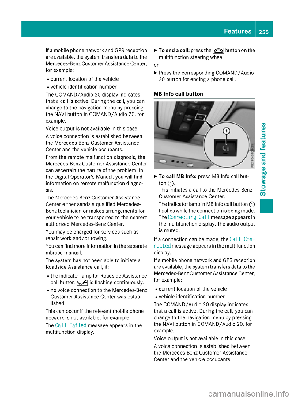
MB Info call button
XTo call MB Info: press MB Info call but-
ton :.
This initiates a call to the Mercedes-Benz
Customer Assistance Center.
The indicator lamp in MB Info call button :
flashes while the connection is being made.
The Connecting
Callmessage appears in
the multifunction display. The audio output
is muted.
If a connection can be made, the Call Con‐
nectedmessage appears in the multifunction
display.
If a mobile phone network and GPS reception
are available, the system transfers data to the
Mercedes-Benz Customer Assistance Center,
for example:
Rcurrent location of the vehicle
Rvehicle identification number
The COMAND/Audio 20 display indicates
that a call is active. During the call, you can
change to the navigation menu by pressing
the NAVI button in COMAND/Audio 20, for
example.
Voice output is not available in this case.
A voice connection is established between
the Mercedes-Benz Customer Assistance
Center and the vehicle occupants.
Features255
Stowage and features
Z
Page 258 of 350
You receive information about operating your
vehicle, about the nearest authorized
Mercedes-Benz Center and about other prod-
ucts and services from Mercedes-Benz.
You can find further information on the
mbrace system under "Owners Online" at
http://www.mbusa.com.
The system has not been able to initiate an
MB Info call, if:
Rthe indicator lamp in MB Info call button
ïis flashing continuously.
Rno voice connection to the Mercedes-Benz
Customer Assistance Center was estab-
lished.
This can occur if the relevant mobile phone
network is not available, for example.
The Call Failed
message appears in the
multifunction display.
XTo end a call: press the~button on the
multifunction steering wheel.
or
XPress the corresponding COMAND/Audio
20 button for ending a phone call.
Call priority
When service calls are active, e.g. Roadside
Assistance or MB Info calls, an emergency
call can still be initiated. In this case, an emer-
gency call will take priority and override all
other active calls.
The indicator lamp of the respective button
flashes until the call is ended.
An emergency call can only be terminated by the Mercedes-Benz Customer Assistance
Center.
All other calls can be ended by pressing:
Rthe ~ button on the multifunction steer-
ing wheel
Rthe corresponding button in COMAND/
Audio 20 to end the voice call
When a call is initiated, the audio system is
muted. The mobile phone is no longer connected to
COMAND/Audio 20.
However, if you want to use your mobile
phone, do so only when the vehicle is station-
ary and in a safe location.
Garage door opener
General notes
The HomeLink®garage door opener integra-
ted in the rear-view mirror allows you to oper-
ate up to three different door and gate sys-
tems.
Use the integrated garage door opener only
on garage doors that:
Rhave safety stop and reverse features and
Rmeet current U.S. federal safety standards
Once programed, the integrated garage door
opener in the rear-view mirror will assume the
function of the garage door system's remote
control. Please also read the operating
instructions for the garage door system.
When programming a garage door opener,
park the vehicle outside the garage. Do not
run the engine while programming.
Certain garage door drives are incompatible
with the integrated garage door opener. If you
have difficulty programing the integrated
garage door opener, contact an authorized
Mercedes-Benz Center.
Alternatively, you can call the following tele-
phone assistance services:
RUSA: Mercedes-Benz Customer Assistance
Center at 1-800-FOR-MERCedes
RCanada: Customer Service at
1-800-387-0100
RHomeLink®hotline 1-800-355-3515 (free
of charge)
More information on HomeLink
®and/or
compatible products is also available online
at http://www.homelink.com.
Notes on the declaration of conformity
(
Ypage 31).
256Features
Stowage and features
Page 264 of 350
Useful information
i
This Operator's Manual describes all
models and all standard and optional equip-
ment of your vehicle available at the time of
publication of the Operator's Manual.
Country-specific differences are possible.
Please note that your vehicle may not be
equipped with all features described. This
also applies to safety-related systems and
functions.
iRead the information on qualified special-
ist workshops (
Ypage 31).
Engine compartment
Hood
Important safety notes
GWARNING
If the hood is unlatched, it may open up when the vehicle is in motion and block your view.
There is a risk of an accident.
Never unlatch the hood while driving. Before
every trip, ensure that the hood is locked.
GWARNING
When opening and closing the hood, it may
suddenly fall into the closed position. There is a risk of injury to persons within range of
movement of the hood.
Open and close the hood only when no one is
within its range of movement.
GWARNING
Opening the hood when the engine is over-
heated or when there is a fire in the engine
compartment could expose you to hot gases
or other service products. There is a risk of
injury.
Let an overheated engine cool down before
opening the hood. If there is a fire in the
engine compartment, keep the hood closed
and contact the fire department.
GWARNING
The engine compartment contains moving
components. Certain components, such as
the radiator fan, may continue to run or start
again suddenly when the ignition is off. There is a risk of injury.
If you need to do any work inside the engine
compartment:
Rswitch off the ignition
Rnever reach into the area where there is a
risk of danger from moving components,
such as the fan rotation area
Rremove jewelry and watches
Rkeep items of clothing and hair, for exam-
ple, away from moving parts
GWARNING
The ignition system and the fuel injection sys-
tem work under high voltage. If you touch
components which are under voltage, you
could get an electric shock. There is a risk of
injury.
Never touch components of the ignition sys-
tem or fuel injection system when the ignition
is switched on.
GWARNING
Hybrid vehicles: be sure to read the "HYBRID" supplement. Otherwise, you could fail to rec-
ognize dangers.
Opening the hood
GWARNING
Certain components in the engine compart-
ment, such as the engine, radiator and parts
of the exhaust system, can become very hot.
Working in the engine compartment poses a
risk of injury.
Where possible, let the engine cool down and touch only the components described in the
following.
262Engine compartment
Maintenance and care
Page 266 of 350
Checking the oil level using the oil dip-
stick
GWARNING
Certain components in the engine compart-
ment, such as the engine, radiator and parts
of the exhaust system, can become very hot.
Working in the engine compartment poses a
risk of injury.
Where possible, let the engine cool down and touch only the components described in the
following.
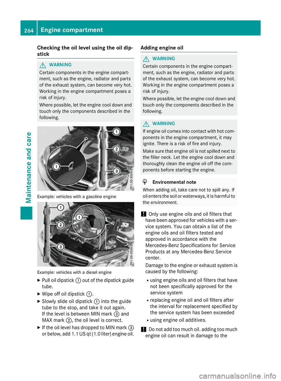
Example :vehicle swit h a gasolin eengin e
Example :vehicle swit h a diesel engin e
XPull oil dipstick :out of the dipstick guide
tube.
XWipe off oil dipstick :.
XSlowly slide oil dipstick :into the guide
tube to the stop, and take it out again.
If the level is between MIN mark =and
MAX mark ;, the oil level is correct.
XIf the oil level has dropped to MIN mark =
or below, add 1.1 US qt (1.0 liter) engine oil.
Adding engine oil
GWARNING
Certain components in the engine compart-
ment, such as the engine, radiator and parts
of the exhaust system, can become very hot.
Working in the engine compartment poses a
risk of injury.
Where possible, let the engine cool down and touch only the components described in the
following.
GWARNING
If engine oil comes into contact with hot com- ponents in the engine compartment, it may
ignite. There is a risk of fire and injury.
Make sure that engine oil is not spilled next to
the filler neck. Let the engine cool down and
thoroughly clean the engine oil off the com-
ponents before starting the engine.
HEnvironmental note
When adding oil, take care not to spill any. If
oil enters the soil or waterways, it is harmful to
the environment.
!Only use engine oils and oil filters that
have been approved for vehicles with a ser-
vice system. You can obtain a list of the
engine oils and oil filters tested and
approved in accordance with the
Mercedes-Benz Specifications for Service
Products at any Mercedes-Benz Service
center.
Damage to the engine or exhaust system is
caused by the following:
Rusing engine oils and oil filters that have
not been specifically approved for the
service system
Rreplacing engine oil and oil filters after
the interval for replacement specified by the service system has been exceeded
Rusing engine oil additives.
!Do not add too much oil. adding too much
engine oil can result in damage to the
264Engine compartment
Maintenance and care
Page 267 of 350
engine or to the catalytic converter. Have
excess engine oil siphoned off.
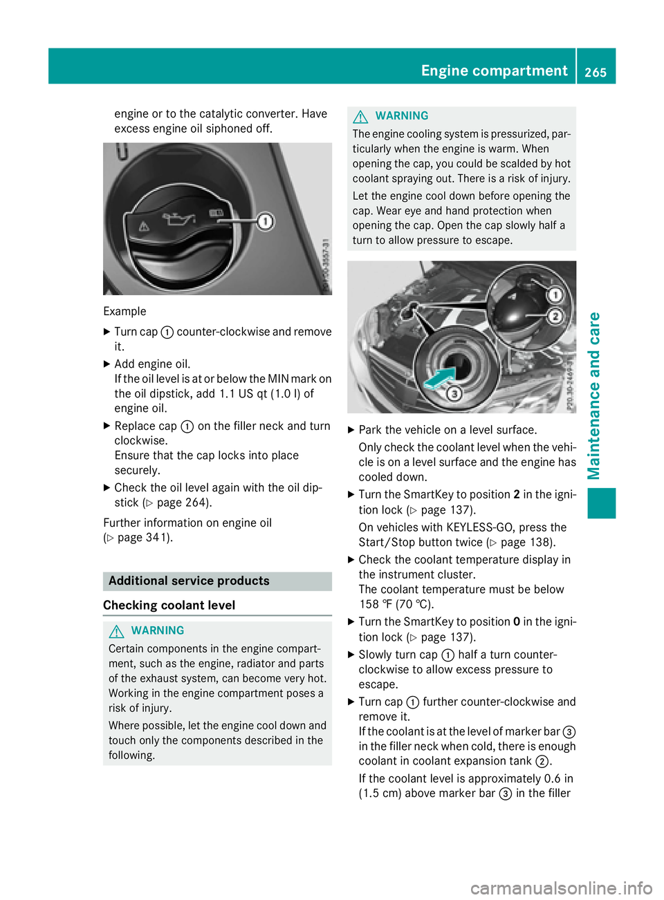
Example
XTurn cap:counter-clockwise and remove
it.
XAdd engine oil.
If the oil level is at or below the MIN mark on
the oil dipstick, add 1.1 US qt (1.0 l)of
engine oil.
XReplace cap :on the filler neck and turn
clockwise.
Ensure that the cap locks into place
securely.
XCheck the oil level again with the oil dip-
stick (
Ypage 264).
Further information on engine oil
(
Ypage 341).
Additional service products
Checking coolant level
GWARNING
Certain components in the engine compart-
ment, such as the engine, radiator and parts
of the exhaust system, can become very hot.
Working in the engine compartment poses a
risk of injury.
Where possible, let the engine cool down and touch only the components described in the
following.
GWARNING
The engine cooling system is pressurized, par-
ticularly when the engine is warm. When
opening the cap, you could be scalded by hot
coolant spraying out. There is a risk of injury.
Let the engine cool down before opening the
cap. Wear eye and hand protection when
opening the cap. Open the cap slowly half a
turn to allow pressure to escape.
XPark the vehicle on a level surface.
Only check the coolant level when the vehi-
cle is on a level surface and the engine has
cooled down.
XTurn the SmartKey to position 2in the igni-
tion lock (
Ypage 137).
On vehicles with KEYLESS-GO, press the
Start/Stop button twice (
Ypage 138).
XCheck the coolant temperature display in
the instrument cluster.
The coolant temperature must be below
158 ‡ (70 †).
XTurn the SmartKey to position 0in the igni-
tion lock (
Ypage 137).
XSlowly turn cap :half a turn counter-
clockwise to allow excess pressure to
escape.
XTurn cap :further counter-clockwise and
remove it.
If the coolant is at the level of marker bar =
in the filler neck when cold, there is enough
coolant in coolant expansion tank ;.
If the coolant level is approximately 0.6 in
(1.5 cm) above marker bar =in the filler
Engine compartment265
Maintenance and care
Z