2016 MERCEDES-BENZ E-SEDAN clock
[x] Cancel search: clockPage 248 of 350
sudden braking or a sudden change in
direction.
Always observe the maximum permitted
load of the EASY-PACK trunk box. Always
store and secure heavy objects in the trunk
outside of the EASY-PACK trunk box.
The maximum permitted load of the EASY-
PACK trunk box is 22 lbs (10 kg). With a load
of above approximately 11 lbs (5 kg), the bot- tom of the box moves downward until it rests
on the mat of the trunk floor. Thus, overload-
ing of the box is avoided.
Adjusting the height to any position
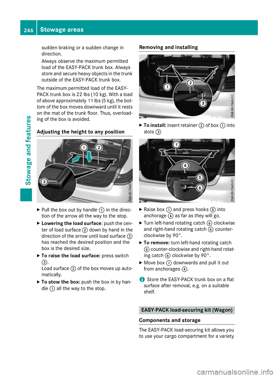
XPull the box out by handle :in the direc-
tion of the arrow all the way to the stop.
XLowering the load surface: push the cen-
ter of load surface ;down by hand in the
direction of the arrow until load surface ;
has reached the desired position and the
box is the desired size.
XTo raise the load surface: press switch
=.
Load surface ;of the box moves up auto-
matically.
XTo stow the box: push the box in by han-
dle :all the way to the stop.
Removing and installing
XTo install: insert retainer ;of box :into
slots =
XRaise box :and press hooks Ainto
anchorage ?as far as they will go.
XTurn left-hand rotating catch Bclockwise
and right-hand rotating catch Bcounter-
clockwise by 90°.
XTo remove: turn left-hand rotating catch
B counter-clockwise and right-hand rotat-
ing catch Bclockwise by 90°.
XMove box :downwards and pull it out
from anchorages ?.
iStore the EASY-PACK trunk box on a flat
surface after removal, e.g. on a suitable
shelf.
EASY-PACK load-securing kit (Wagon)
Components and storage
The EASY-PACK load-securing kit allows you
to use your cargo compartment for a variety
246Stowage areas
Stowage and features
Page 267 of 350
engine or to the catalytic converter. Have
excess engine oil siphoned off.
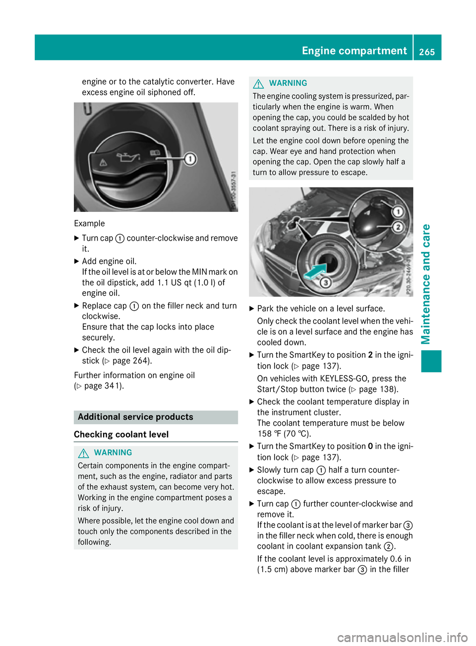
Example
XTurn cap:counter-clockwise and remove
it.
XAdd engine oil.
If the oil level is at or below the MIN mark on
the oil dipstick, add 1.1 US qt (1.0 l)of
engine oil.
XReplace cap :on the filler neck and turn
clockwise.
Ensure that the cap locks into place
securely.
XCheck the oil level again with the oil dip-
stick (
Ypage 264).
Further information on engine oil
(
Ypage 341).
Additional service products
Checking coolant level
GWARNING
Certain components in the engine compart-
ment, such as the engine, radiator and parts
of the exhaust system, can become very hot.
Working in the engine compartment poses a
risk of injury.
Where possible, let the engine cool down and touch only the components described in the
following.
GWARNING
The engine cooling system is pressurized, par-
ticularly when the engine is warm. When
opening the cap, you could be scalded by hot
coolant spraying out. There is a risk of injury.
Let the engine cool down before opening the
cap. Wear eye and hand protection when
opening the cap. Open the cap slowly half a
turn to allow pressure to escape.
XPark the vehicle on a level surface.
Only check the coolant level when the vehi-
cle is on a level surface and the engine has
cooled down.
XTurn the SmartKey to position 2in the igni-
tion lock (
Ypage 137).
On vehicles with KEYLESS-GO, press the
Start/Stop button twice (
Ypage 138).
XCheck the coolant temperature display in
the instrument cluster.
The coolant temperature must be below
158 ‡ (70 †).
XTurn the SmartKey to position 0in the igni-
tion lock (
Ypage 137).
XSlowly turn cap :half a turn counter-
clockwise to allow excess pressure to
escape.
XTurn cap :further counter-clockwise and
remove it.
If the coolant is at the level of marker bar =
in the filler neck when cold, there is enough
coolant in coolant expansion tank ;.
If the coolant level is approximately 0.6 in
(1.5 cm) above marker bar =in the filler
Engine compartment265
Maintenance and care
Z
Page 268 of 350
neck when warm, there is enough coolant
in expansion tank;.
XIf necessary, add coolant that has been tes-
ted and approved by Mercedes-Benz.
XReplace cap:and turn it clockwise as far
as it will go.
For further information on coolant, see
(
Ypage 342).
Adding washer fluid to the windshield
washer system
GWARNING
Certain components in the engine compart-
ment, such as the engine, radiator and parts
of the exhaust system, can become very hot.
Working in the engine compartment poses a
risk of injury.
Where possible, let the engine cool down and touch only the components described in the
following.
GWARNING
Windshield washer concentrate could ignite if it comes into contact with hot engine compo-
nents or the exhaust system. There is a risk of
fire and injury.
Make sure that no windshield washer con-
centrate is spilled next to the filler neck.
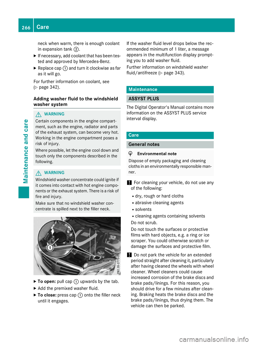
XTo open: pull cap:upwards by the tab.
XAdd the premixed washer fluid.
XTo close: press cap :onto the filler neck
until it engages. If the washer fluid level drops below the rec-
ommended minimum of 1 liter, a message
appears in the multifunction display prompt-
ing you to add washer fluid.
Further information on windshield washer
fluid/antifreeze (
Ypage 343).
Maintenance
ASSYST PLUS
The Digital Operator's Manual contains more
information on the ASSYST PLUS service
interval display.
Care
General notes
HEnvironmental note
Dispose of empty packaging and cleaning
cloths in an environmentally responsible man-
ner.
!For cleaning your vehicle, do not use any
of the following:
Rdry, rough or hard cloths
Rabrasive cleaning agents
Rsolvents
Rcleaning agents containing solvents
Do not scrub.
Do not touch the surfaces or protective
films with hard objects, e.g. a ring or ice
scraper. You could otherwise scratch or
damage the surfaces and protective film.
!Do not park the vehicle for an extended
period straight after cleaning it, particularly
after having cleaned the wheels with wheel
cleaner. Wheel cleaners could cause
increased corrosion of the brake discs and
brake pads/linings. For this reason, you
should drive for a few minutes after clean-
ing. Braking heats the brake discs and the
brake pads/linings, thus drying them. The
vehicle can then be parked.
266Care
Maintenance and care
Page 280 of 350
cialist workshop if you wish to leave your
vehicle parked for a long period of time.
iRemove the SmartKey if you park the
vehicle and do not require any electrical
consumers. The vehicle will then use very
little energy, thus conserving battery
power.
iIf the power supply has been interrupted,
e.g. if you reconnect the battery, you will
have to:
Rset the clock. Information on setting the
clock can be found in the Digital Opera-
tor's Manual.
On vehicles with COMAND and a naviga-
tion system, the clock is set automati-
cally.
Rreset the function for folding the exterior mirrors in/out automatically, by folding
the mirrors out once (
Ypage 117).
Charging the battery
GWARNING
During charging and jump-starting, explosive
gases can escape from the battery. There is a risk of an explosion.
Particularly avoid fire, open flames, creating
sparks and smoking. Ensure there is sufficient
ventilation while charging and jump-starting.
Do not lean over a battery.
GWARNING
Battery acid is caustic. There is a risk of injury.
Avoid contact with skin, eyes or clothing. Do
not inhale any battery gases. Do not lean over
the battery. Keep children away from batter-
ies. Wash away battery acid immediately with
plenty of clean water and seek medical atten-
tion.
GWARNING
A discharged battery can freeze at tempera-
tures below freezing point. When jump-start-
ing the vehicle or charging the battery, gases
can escape from the battery. There is a risk of an explosion.
Allow the frozen battery to thaw out before
charging it or jump-starting.
!Only use battery chargers with a maxi-
mum charging voltage of 14.8 V.
!Onlycharge the battery using the jump-
starting connection point.
The jump-starting connection point is in the
engine compartment (
Ypage 279).
XOpen the hood.
XConnect the battery charger to the positive
terminal and ground point in the same
order as when connecting the donor bat-
tery in the jump-starting procedure
(
Ypage 279).
If the indicator/warning lamps do not light up
at low temperatures, it is very likely that the
discharged battery has frozen. In this case,
you may neither charge the battery nor jump-
start the vehicle. The service life of a thawed- out battery may be shorter. The starting char-
acteristics may be impaired, especially at low
temperatures. Have the thawed-out battery
checked at a qualified specialist workshop.
Never charge a battery still installed in the
vehicle unless a battery charger unit
approved by Mercedes-Benz is being used . A
battery charger unit specially adapted for
Mercedes-Benz vehicles and tested and
approved by Mercedes-Benz is available as anaccessory. It permits the charging of the bat-
tery in its installed position. Contact an
authorized Mercedes-Benz Center for further
informa
tion and availability. Read the battery
charger's operating instructions before
charging the battery.
278Battery (vehicle)
Roadside Assistance
Page 285 of 350
XTake cover:off the opening.
XScrew in the towing eye clockwise as far as
it will go and tighten it.
Removing the towing eye
XUnscrew and remove the towing eye.
XAttach cover :to the bumper and press
until it engages.
XPlace the towing eye in the vehicle tool kit.
Towing a vehicle with both axles on
the ground
It is important that you observe the safety
instructions when towing away your vehicle
(
Ypage 281).
The automatic transmission automatically
shifts to position Pwhen you open the driver's
or front-passenger door or when you remove
the SmartKey from the ignition lock. In order
to ensure that the automatic transmission
stays in position Nwhen towing the vehicle,
you must observe the following points:
XMake sure that the vehicle is stationary and
the SmartKey in the ignition lock is in posi- tion 0.
XTurn the SmartKey to position 2in the igni-
tion lock.
On vehicles with KEYLESS-GO, use the
SmartKey instead of the Start/Stop button
(
Ypage 139).
XDepress and hold the brake pedal.
XShift the automatic transmission to posi-
tion N.
XRelease the brake pedal.
XRelease the parking brake.
XSwitch on the hazard warning lamps, see
the Digital Operator's Manual.
XLeave the SmartKey in position 2in the
ignition lock.
iWhen towing with the hazard warning
lamps switched on, use the combination
switch as usual to signal a change of direc- tion. In this case, only the indicator lamps
for the direction of travel flash. After reset-
ting the combination switch, the hazard
warning lamp starts flashing again.
Towing the vehicle with the rear axle
raised
!
Vehicles with 4MATIC must not be towed
with either the front or the rear axle raised,
as doing so will damage the transmission.
!Vehicles with automatic transmission
must not be towed with the rear axle raised.
The vehicle/trailer combination may oth-
erwise swerve or even roll over.
!The ignition must be switched off if you
are towing the vehicle with the rear axle
raised. Intervention by ESP
®could other-
wise damage the brake system.
Transporting the vehicle
!
You may only secure the vehicle by the
wheels, not by parts of the vehicle such as
axle or steering components. Otherwise,
the vehicle could be damaged.
The towing eye can be used to pull the vehicle
onto a trailer or transporter for transporting
purposes.
XTurn the SmartKey to position 2in the igni-
tion lock.
XShift the automatic transmission to posi-
tion N.
As soon as the vehicle has been loaded:
XPrevent the vehicle from rolling away by
applying the parking brake.
XShift the automatic transmission to posi-
tion P.
XTurn the SmartKey to position 0in the igni-
tion lock and remove the SmartKey from
the ignition lock.
XSecure the vehicle.
Towing and tow-starting283
Roadside Assistance
Z
Page 313 of 350

!The jack is designed exclusively for jack-
ing up the vehicle at the jacking points.
Otherwise, your vehicle could be damaged.
Observe the following when raising the vehi-
cle:
RTo raise the vehicle, only use the vehicle-
specific jack that has been tested and
approved by Mercedes-Benz. If used incor-
rectly, the jack could tip over with the vehi- cle raised.
RThe jack is designed only to raise and hold
the vehicle for a short time while a wheel
is being changed. It is not suited for per-
forming maintenance work under the vehi-
cle.
RAvoid changing the wheel on uphill and
downhill slopes.
RBefore raising the vehicle, secure it from
rolling away by applying the parking brake
and inserting wheel chocks. Never disen-
gage the parking brake while the vehicle is
raised.
RThe jack must be placed on a firm, flat andnon-slip surface. On a loose surface, a
large, flat, load-bearing underlay must be
used. On a slippery surface, a non-slip
underlay must be used, e.g. rubber mats.
RDo not use wooden blocks or similar
objects as a jack underlay. Otherwise, the
jack will not be able to achieve its load-
bearing capacity due to the restricted
height.
RMake sure that the distance between the
underside of the tires and the ground does
not exceed 1.2 in (3 cm).
RNever place your hands and feet under the
raised vehicle.
RDo not lie under the vehicle.
RDo not start the engine when the vehicle is
raised.
RDo not open or close a door or the trunk lid/
tailgate when the vehicle is raised.
RMake sure that no persons are present in
the vehicle when the vehicle is raised. AMG vehicles with Performance Studio
equipment:
the wheel bolts are covered by a
hub cap. Before you can unscrew the wheel
bolts, you must remove the hub cap.
XTo remove: turn the center cover of hub
cap :counter-clockwise and remove.
XTo install: before installing, ensure that
hub cap :is in the open position. To do
this, turn the center cover counter-clock-
wise.
XPosition hub cap :and turn the center
cover clockwise until hub cap :engages
physically and audibly.
XMake sure that hub cap :is installed
securely.
XUsing lug wrench ;, loosen the bolts on
the wheel you wish to change by about one
full turn. Do not unscrew the bolts com-
pletely.
Changing a wheel311
Wheels and tires
Z
Page 314 of 350

Jacking points (example: Sedan)
The jacking points are located just behind thefront wheel housings and just in front of the
rear wheel housings (arrows).
AMG vehicles and vehicles with AMG
equipment: to protect the vehicle body, the
vehicle has covers next to the jacking points
on the outer sills.
Cover, front (example: vehicles with AMG Sports
package)
XAMG vehicles and vehicles with AMG
equipment: fold cover=upwards.
XPosition jack Aat jacking point ?.
XMake sure the foot of the jack is directly
beneath the jacking point.
XTurn crankBclockwise until jack Asits
completely on jacking point ?. The base of
the jack must lie evenly on the ground.
XTurn crank Buntil the tire is raised a max-
imum of 1.2 in (3 cm) from the ground.
Removing a wheel
!AMG vehicles: during removal and repo-
sitioning of the wheel, the wheel rim can
strike the ceramic-brake disc and damage
it. Therefore, you should proceed carefully
and get a second person assist to you.
Alternatively, you can use a second align-
ment bolt.
!Do not place wheel bolts in sand or on a
dirty surface. The bolt and wheel hub
threads could otherwise be damaged when
you screw them in.
312Changing a wheel
Wheels and tires
Page 316 of 350
XTurn the crank of the jack counter-clock-
wise until the vehicle is once again standing
firmly on the ground.
XPlace the jack to one side.
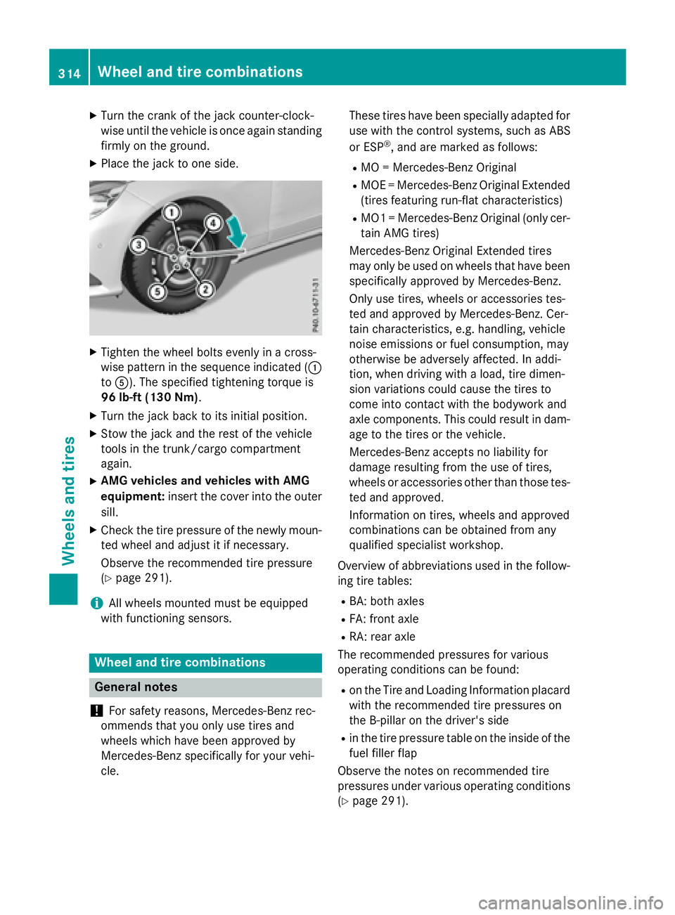
XTighten the wheel bolts evenly in a cross-
wise pattern in the sequence indicated (:
to A). The specified tightening torque is
96 lb-ft (130 Nm).
XTurn the jack back to its initial position.
XStow the jack and the rest of the vehicle
tools in the trunk/cargo compartment
again.
XAMG vehicles and vehicles with AMG
equipment: insert the cover into the outer
sill.
XCheck the tire pressure of the newly moun-
ted wheel and adjust it if necessary.
Observe the recommended tire pressure
(
Ypage 291).
iAll wheels mounted must be equipped
with functioning sensors.
Wheel and tire combinations
General notes
!
For safety reasons, Mercedes-Benz rec-
ommends that you only use tires and
wheels which have been approved by
Mercedes-Benz specifically for your vehi-
cle. These tires have been specially adapted for
use with the control systems, such as ABS
or ESP
®, and are marked as follows:
RMO = Mercedes-Benz Original
RMOE = Mercedes-Benz Original Extended
(tires featuring run-flat characteristics)
RMO1 = Mercedes-Benz Original (only cer-
tain AMG tires)
Mercedes-Benz Original Extended tires
may only be used on wheels that have been
specifically approved by Mercedes-Benz.
Only use tires, wheels or accessories tes-
ted and approved by Mercedes-Benz. Cer-
tain characteristics, e.g. handling, vehicle
noise emissions or fuel consumption, may
otherwise be adversely affected. In addi-
tion, when driving with a load, tire dimen-
sion variations could cause the tires to
come into contact with the bodywork and
axle components. This could result in dam-
age to the tires or the vehicle.
Mercedes-Benz accepts no liability for
damage resulting from the use of tires,
wheels or accessories other than those tes-
ted and approved.
Information on tires, wheels and approved
combinations can be obtained from any
qualified specialist workshop.
Overview of abbreviations used in the follow-
ing tire tables:
RBA: both axles
RFA: front axle
RRA: rear axle
The recommended pressures for various
operating conditions can be found:
Ron the Tire and Loading Information placard with the recommended tire pressures on
the B-pillar on the driver's side
Rin the tire pressure table on the inside of the
fuel filler flap
Observe the notes on recommended tire
pressures under various operating conditions
(
Ypage 291).
314Wheel and tire combinations
Wheels and tires