2016 MERCEDES-BENZ E-CLASS SALOON suspension
[x] Cancel search: suspensionPage 127 of 557

#
4 Ã Automatic driving lights (prefer red
light switch position) #
5 L Dipped beam/main beam #
6 R Switches there ar fog light on or off
When dipped beam is activated, the indicator
lamp forth est anding lights is deactivated and
re placed bythe dipped beam indicator lamp.
Alw ays park your vehicle safely and in a well-lit
area, in accordance with there leva nt le galst ipu‐
lations.
* NO
TEBattery discharging byoperating
th est anding lights Operating
thest anding lights over a period of
hours puts a stra in on the batter y. #
Where possible, switch on the
ri ght X or left Wparking light. In
the case of se vere battery discharging, the
st anding lights or parking lights are automati‐
cally swit ched off tofacilitate a futu reengine
st art. The
exterior lighting (e xcept standing and park‐
ing lights) swit ches off automatically when the
driver's door is opened.
Au tomatic driving lights
The standing lights, dipped beam and daytime
ru nning lights are switched on au tomatical ly
depending on the ignition status, whe ther the
engine is running and on the light conditions. &
WARNING Risk of accident when the
dipped beam is switched off in poor visi‐
bility
When the light switch is set toà ,the
dipped beam may not be switched on auto‐
matically if there is fog, snow or other causes
of poor visibility such as spr ay. #
In such cases, turn the light switch to
L . The automatic driving lights are only an aid.
Yo u
are responsible forve hicle lighting. Ac
tivating/deactivating the rear fog light
Re quirement
The light switch is in theL orà position. #
Press button R.
Please obser vethe count ry-specific la wsonthe
use of rear fog lamps.
Ad justing the headlamp range (halogen
headla mps without active suspension)
The headlamp range adjus ter allows youto
adjust the cone of light from the headlamps in
re lation totheve hicle's load condition. 124
Light and sight
Page 163 of 557

The inner segment lights up green and
the outer
segment fills up:
R 1 Moderate acceleration
R 2 Gentle decele ration and rolling
R 3 Consis tent speed
The inner segment is gr eyand the outer seg‐
ment em pties:
R 1 Sporty acceleration
R 2 Heavy braking
R 3 Fluctuations in speed Yo
u ha vedriven economically when:
R theth re e outer segments are comple tely fil‐
led simultaneousl y.
R the ECO display border lights up.
The additional range achi eved as a result of your
driving style in comparison toa driver with a
ve ry sporty driving style is shown under Bonus
from start. The range displ ayed does not indicate
a fixe dre duction in consum ption. DY
NA MIC SELECT switch Fu
nction of theDY NA MIC SELECT switch Plug-in
hybrid: obser vethe no tes on the
DY NA MIC SELECT switch in the separate operat‐
ing instructions.
Use theDY NA MIC SELECT switch tochange
between thefo llowing drive programs:
R I (Individual): individual settings
R S+ (Sport Plus): particularly sporty driving
st yle
R S (Sport): sporty driving style R
C (Comfort): comfortable and economical
driving style
R E (Economy): particularly economical driving
st yle
Depending on the drive program selected, the
fo llowing vehicle characteristics will change:
R Drive sy stem
- Engine and transmission management
- ESP ®
- Distance Pilot DISTRONIC
R Suspension
R Steering
R Availability of the ECO start/ stop function
% Time until the next vehicle star t:
R Less than four hours: the last selected
drive program is active.
R More than four hours: drive program Cis
active. 16 0
Driving and pa rking
Page 208 of 557

%
Once you ha veswitched off the engine, you
cannot restart the engine until you ha ve
deactivated the HOLD function. DY
NA MIC BODY CONT ROL DY
NA MIC BODY CONTROL has thefo llowing
ch aracteristics:
R Variable damping characteristics
R Continual adjustment of the damping forc es
The damping characteristics adapt tothe cur rent
operating and driving situation.
The da mping is tuned individually for each wheel
and is af fected bythefo llowing factors:
R The road sur face conditions R
The drive program selected
R Vehicle load
The drive program can be adjus ted using the
DY NA MIC SELECT switch. AIR
BODY CONT ROL AIR
BODY CONT ROL function
AIR BODY CONTROL is an air suspension sy stem
with variable damping for impr oved driving com‐
fo rt. The all-round le vel control sy stem ensures
th e best possible suspension and const ant
ground clea rance, even wi tha laden vehicle.
When driving at speed, theve hicle is lo wered
automatically toimpr ove driving saf ety and to re
duce fuel consum ption. The option of manually
adjusting theve hicle le vel is also available.
AIR BODY CONTROL comprises:
R Air suspension with variable spring rate
R Automatic le vel control sy stem
R Speed-dependent lo wering toreduce fuel
consum ption
R Manual le vel adjustment
R ADS PLUS (Adaptive Damping Sy stem with
const ant damping forc e adjustment)
R DYNA MIC SELECT switch and le vel button Driving and parking
205
Page 209 of 557

Av
ailable suspension settings Drive prog
ramC haracteristics
C
(Comfort) R
Comfor table suspension tuning
R Normal le vel
R When driving at speeds abo ve125 km/h theve hicle is lo weredby 15 mm
R When driving at speeds below 80 km/h, theve hicle is raised again
E
(Econo my) R
Comfor table suspension tuning
R The vehicle is lo weredby 15 mm compared tothe normal le vel
R The vehicle is not lo wered any fur ther if you are tra velling at higher speeds
S
(Sport) R
Firmer suspension tuning
R The vehicle is lo weredby 15 mm compared tothe normal le vel
R The vehicle is not lo wered any fur ther if you are tra velling at higher speeds
S+
(Sport Plus) R
Even firm er suspension tuning
R The vehicle is lo weredby 15 mm compared tothe normal le vel
R The vehicle is not lo wered any fur ther if you are tr avelling at higher speeds 206
Driving and parking
Page 219 of 557

Guide lines
1
Yellow lane marking the course the tyres will
ta ke atthe cur rent steering wheel angle
(dynamic)
2 Yellow guide line, vehicle width (driven sur‐
fa ce) depending on the cur rent steering
wheel angle (dynamic)
3 Red guide line at a dis tance of appr oximately
0.3 m from there ar area
4 Mark at a distance of appr ox.1. 0 m
% When Parking Pilot is active, the lanes are
displa yed in green. The guide lines in
the multimedia sy stem dis‐
play show the dis tances toyour vehicle. The
dis tances only apply toroad le vel. In trailer
mode, the guide lines are shown at the le vel
of the trailer hitch.
Sy stem limitations
The 360° Camera will not function or will only
partially function in thefo llowing situations:
R Ifth e doors are open.
R The side mir rors are folded in.
R Ifth e boot lid or tailgate is open.
R Ifth ere is heavy rain, snow or fog.
R Ifth e light conditions are poor, e.g. at night.
R Ifth e camera lens is obstructed, dirty or mis‐
te d up.
R Ifth eve hicle components in which the cam‐
eras are fitted are dama ged. In this event,
ha ve the camera position and setting
ch ecked at a qualified specialist workshop.
Do not use the 360° Camera under such circum‐
st ances. You could otherwise injure others or
collide with objects when parking theve hicle. On
vehicles with height-adjus table suspension or
if th eve hicle is car rying a heavy load, leaving the
st andard height can result in inaccuracies in the
guide lines and in the display of thege nerated
ima ges, depending on tech nical conditions.
The field of vision and other functions of the
came rasystem may be restricted due toaddi‐
tional accesso ries on there ar of theve hicle (e.g.
licence plate brac ket, bicycle rack ).
See the no tes on cleaning the 360° Camera
(→ page 374).
Selecting a view for the 360° Camera
The Auto reversing camera function is selected
in the multimedia sy stem. #
Enga gereve rsege ar. #
Inthe multimedia sy stem, select the desired
vie w.
Switching reve rsing camera automatic mode
on/off
The reve rsing camera is only an aid. It is not a
substitute foryo ur attention tothe sur roundings.
The responsibility for safe manoeuvring and
parking remains with you. Make sure that no 216
Driving and pa rking
Page 413 of 557

&
WARNING Risk of accident due toincor‐
re ct dimensions of wheels and tyres
If wheels and tyres of the wrong size are
used, the wheel brakes or wheel suspension
components may become damaged. #
Alw aysre place wheels and tyres with
th ose that fulfil the specifications of the
original part.
When replacing wheels, make sure tofit the
cor rect:
R Designation
R Type
When replacing tyres, make sure tofit the
cor rect:
R Designation
R Manufactu rer
R Type &
WARNING Risk of inju rythro ugh exceed‐
ing the specified tyre load-bearing capa‐
city or the permissible speed rating
Exceeding the specified tyre load-bearing
capacity or the permissible speed rating may
lead totyre dama geand tothe tyres bur st‐
ing. #
Therefore, only use tyre types and sizes
appr ovedfo ryo ur vehicle model. #
Obser vethe tyre load-bearing capacity
ra ting and speed rating requ iredfor
yo ur vehicle. *
NO
TEDama getovehicle and tyres due
to non-app rove d tyre types and sizes Fo
r saf etyre asons, on lyuse wheels, tyres
and accessories which ha vebeen appr oved
fo ryo ur vehicle byMercedes-Benz. These tyres ha
vebeen specially adap tedfor
use with the control sy stems, e.g. ABS or
ESP ®
, and are mar ked as follo ws:
R MO = Mercedes-Benz Original
R MOE = Mercedes-Benz Original Extended
(run-flat tyres only for cer tain wheels)
R MO1 = Mercedes-Benz Original (only cer‐
tain AMG tyres)
Cer tain characteristics, e.g. handling, vehicle
noise emissions or fuel consum ption, may
ot herwise be adversely af fected. In addition,
when driving wi tha load, tyre dimension var‐
iations could cause the tyres tocome into
contact wi th the body and axle components.
This could result in damage tothe tyres or
th eve hicle.
Only use tyres, wheels or accessories tested
and appr oved byMercedes-Benz. 41 0
Wheels and tyres
Page 416 of 557

may se
verely impair the driving characteris‐
tics.
The disk brakes or wheel suspension compo‐
nents may also be damaged. #
Rotate front and rear wheels on lyifthe
wheels and tyres are of the same
dimensions. Inter
changing the front and rear wheels if the
wheels or tyres ha vediffere nt dimensions can
re nder thege neral operating pe rmit in valid.
The wear pat tern s on the front and rear wheels
dif fer:
R Front wheels wear more on the shoulder of
th e tyre
R Rear wheels wear more in the cent reofthe
tyre
On vehicles with the same front and rear wheel
size, you can inter change the wheels every
5000 to10000 km, depending on thewe ar.
Ensure the direction of rotation is maintained for
th e wheels. It is imperative
toobser vethe instructions and
saf ety no tes on "Wheel change" when doing so. Note
s onstoring wheels R
Afterre moving wheels, store them in a cool,
dry and preferably dark place.
R Protect the tyres from conta ct withoil,
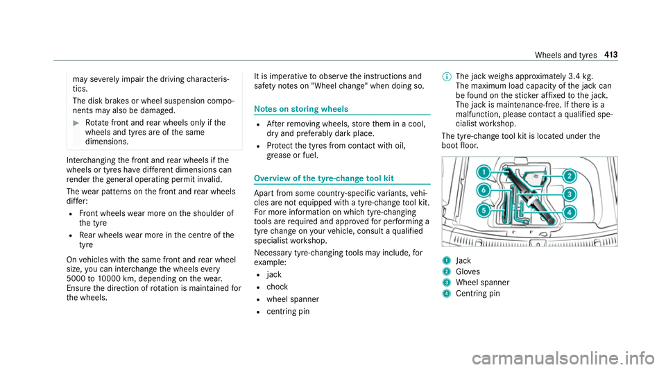
grease or fuel. Overview of
the ty re-change tool kit Apart from some countr
y-specific variants, vehi‐
cles are not equipped with a tyre-change tool kit.
Fo r more information on which tyre-changing
to ols are requ ired and appr ovedfo r per form ing a
tyre change on your vehicle, consult a qualified
specialist workshop.
Necessary tyre-changing tools may include, for
ex ample:
R jack
R chock
R wheel spanner
R centri ng pin %
The jack weighs appr oximately 3.4 kg.
The maximum load capacity of the jack can
be found on thest icke r af fixe dto the jac k.
The jack is maintenance-free. If there is a
malfunction, please conta ct aqualified spe‐
cialist workshop.
The tyre-change tool kit is located under the
boot floor. 1
Jack
2 Gloves
3 Wheel spanner
4 Centring pin Wheels and tyres
413
Page 436 of 557

The proportion of cor
rosion inhibitor/ antifreeze
concentrate in the engine cooling sy stem should
be:
R A minimum of 50% (antifreeze pr otection
down toappr oximately -37 °C).
R A maximum of 55% (antifreeze pr otection
down to-45 °C). Note
s on windscreen washer fluid Obser
vethe no tes on operating fluids
(→ page 425). &
WARNING ‑ Risk of fire and injury due to
windscreen washer concentrate
Wi ndsc reen washer concentrate is highly
fl ammable. It could ignite if it comes into
con tact wi thhot engine component parts or
th eex haust sy stem. #
Make sure that no windsc reen washer
concentrate spills out next tothefiller
opening. *
NO
TEDama getotheex terior lighting
due tounsuitable windsc reen washer
fl uid Uns
uitable windsc reen washer fluids may
damage the plastic sur face of theex terior
lighting. #
Only use windscreen washer fluids
which are also suitable for use on plas‐
tic sur faces, e.g. MB SummerFit or MB
Wi nterFit. *
NO
TEBlocked spr aynozzles caused by
mixing windscreen washer fluids #
Do not mix MB SummerFit and MB Win‐
te rFit with other windscreen washer flu‐
ids. Do not use distilled or de-ionised
water asthefill
le ve l sensor may be triggered er roneously.
Re commended windscreen washer fluid:
R Abo vefreezing point: e.g. MB SummerFit
R Below freezing point: e.g. MB WinterFit Fo
rth e cor rect mixing ratio referto the informa‐
tion on the antif reeze reser voir.
Mix thewa sher fluid with the windscreen washer
fl uid all year round. Ve
hicle data Ve
hicle dimensions The heights speci
fied may vary as a result of the:
R tyres
R load
R condition of the suspension
R optional equipment Te
ch nical da ta433