2016 MERCEDES-BENZ CLA COUPE boot
[x] Cancel search: bootPage 296 of 345
Where will I find...?
Warning triangle
Removing/replacing the warning trian-
gle X
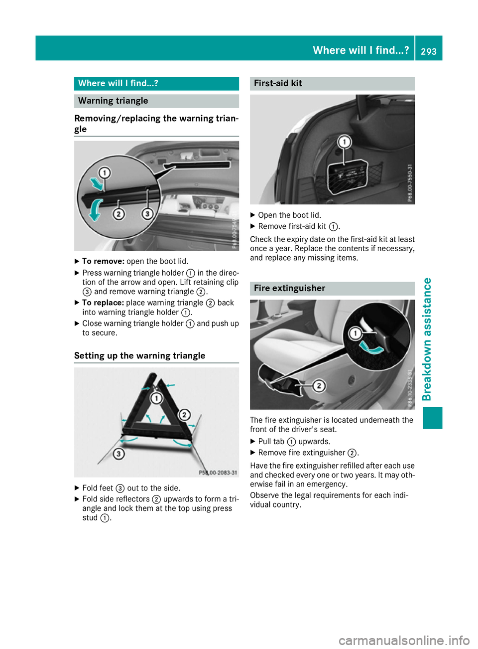
To remove: open the boot lid.
X Press warning triangle holder :in the direc-
tion of the arrow and open. Lift retaining clip
= and remove warning triangle ;.
X To replace: place warning triangle ;back
into warning triangle holder :.
X Close warning triangle holder :and push up
to secure.
Setting up the warning triangle X
Fold feet =out to the side.
X Fold side reflectors ;upwards to form a tri-
angle and lock them at the top using press
stud :. First-aid kit
X
Open the boot lid.
X Remove first-aid kit :.
Check the expiry date on the first-aid kit at least
once a year. Replace the contents if necessary,
and replace any missing items. Fire extinguisher
The fire extinguisher is located underneath the
front of the driver's seat.
X Pull tab :upwards.
X Remove fire extinguisher ;.
Have the fire extinguisher refilled after each use and checked every one or two years. It may oth-
erwise fail in an emergency.
Observe the legal requirements for each indi-
vidual country. Where will I find...?
293Breakdown assistance
Page 297 of 345

Vehicle tool kit
General notes Vehicles with a TIREFIT kit: the TIREFIT kit is
located in the stowage well under the boot floor.
Vehicles with a tyre-change tool kit: the tyre-
change tool kit is in the stowage well under the
boot floor.
Vehicles with an emergency spare wheel, see
"Removing the emergency spare wheel"
(Y page 324).
Apart from some country-specific variants, vehi-
cles are not equipped with a tyre-change tool kit. Some tools for changing a tyre are specific to
the vehicle. For more information on which tyre-
changing tools are required and approved for
performing a tyre change on your vehicle, con-
sult a qualified specialist workshop.
Necessary tyre-changing tools may include, for
example:
R jack
R wheel chock
R Wheel wrench
R Centring pin
i The jack weighs approximately 3.4 kg.
The maximum load-bearing capacity of the
jack can be found on the adhesive label on the jack.
The jack is maintenance-free. If there is a
malfunction, please contact a qualified spe-
cialist workshop.
Vehicles with a TIREFIT kit :
Tyre inflation compressor
; Tyre sealant bottle
= Towing eye X
Open the boot lid.
X Swing the boot floor upwards (Y page 272).
X Use the TIREFIT kit (Y page 296)or remove it.
Towing eye =is located under tyre inflation
compressor :.
i The tyre inflation compressor weighs
approximately 0.8 kg.
The tyre inflation compressor is maintenance-
free. If there is a malfunction, please contact a qualified specialist workshop.
Vehicles with a tyre-change tool kit X
Open the boot lid.
X Swing the boot floor upwards (Y page 272).
X Remove the tyre-change tool kit.
The tyre-change tool kit contains:
R Jack
R Wheel wrench
R One pair of gloves
R Folding wheel chock Flat tyre
Preparing the vehicle
Your vehicle may be equipped with:
R MOExtended tyres (tyres with run-flat char-
acteristics) (Y page 295)
Vehicle preparation is not necessary on vehi- cles with MOExtended tyres.
R a TIREFIT kit (Y page 294)
R an emergency spare wheel (certain countries
only) (Y page 323)
Vehicles with MOExtended tyres are not equip-
ped with a TIREFIT kit at the factory. It is there-
fore recommended that you additionally equip
your vehicle with a TIREFIT kit if you fit tyres that do not feature run-flat characteristics, e.g. win-
ter tyres. A TIREFIT kit can be obtained from a
qualified specialist workshop.
Information on changing and fitting a wheel
(Y page 318).
X Stop the vehicle as far away as possible from
traffic on solid, non-slippery and level ground.
X Switch on the hazard warning lamps.
X Secure the vehicle against rolling away
(Y page 155). 294
Flat tyreBreakdown assistance
Page 300 of 345

X
Do not remove any foreign objects that have
penetrated the tyre, e.g. screws or nails.
X Remove the tyre sealant bottle, the accom-
panying TIREFIT sticker and the tyre inflation
compressor from the stowage space under
the boot floor (Y page 294).
X Affix part :of the TIREFIT sticker to the
instrument cluster within the driver's field of
vision.
X Affix part ;of the TIREFIT sticker near the
valve on the wheel with the defective tyre. X
Remove filler hose Band connector =from
the bottom section of tyre inflation compres- sor housing ;.
X Slide the yellow filler hose connector into the
mounting on yellow cap Aof tyre sealant
bottle :until the connector engages.
X With sealing rings in front, slide yellow cap A
of tyre sealant bottle :into the holder of tyre
inflation compressor ;.
Yellow cap Amust engage in both hooks. X
Remove cap from valve Con faulty tyre.
X Screw filler hose Donto valve C.
X Insert connector =into a 12 V socket in your
vehicle. Observe the notes on sockets (Y
page 276).
X Turn the key to position 1in the ignition lock
(Y page 133).
X Press on and off switch ?on the tyre inflation
compressor to ON.
The tyre inflation compressor is switched on.
The tyre is inflated.
First, tyre sealant is pumped into the tyre. The pressure may briefly rise to approximately
500 kPa (5 bar/73 psi).
Do not switch off the tyre inflation com-
pressor during this phase.
X Let the tyre inflation compressor run for a
maximum of ten minutes. The tyre should
then have attained a pressure of at least
200 kPa (2.0 bar/29 psi).
If a pressure of 200 kPa (2.0 bar/29 psi) has
been attained after ten minutes, see "Tyre pres- sure reached" (Y page 298).
If a tyre pressure of 200 kPa (2.0 bar/29 psi) has not been attained after ten minutes, see "Tyre
pressure not reached" (Y page 297).
If tyre sealant leaks out, make sure you clean the
affected area as quickly as possible. It is pref-
erable to use clear water.
If you get tyre sealant on your clothing, have it
cleaned as soon as possible with perchloroethy- lene.
Tyre pressure not reached If a tyre pressure of 200 kPa (2.0 bar/29 psi) has
not been attained after ten minutes:
X Switch off the tyre inflation compressor.
X Unscrew the filler hose from the valve of the
faulty tyre.
Please note that tyre sealant may leak out
when unscrewing the filler hose.
X Very slowly drive forwards or reverse approx-
imately 10 m.
X Pump up the tyre again.
After a maximum of ten minutes, the tyre
pressure must be at least 200 kPa (2.0 ba r/
29 psi). G
WA
RNING
If the required tyre pressure is not reached
after the specified time, the tyre is too badly
damaged. The tyre sealant cannot repair the
tyre in this instance. Damaged tyres and a tyre Flat tyre
297Breakdown assistance
Z
Page 323 of 345
Raising the vehicle
G
WARNING
If you do not position the jack correctly at the appropriate jacking point of the vehicle, the
jack could tip over with the vehicle raised.
There is a risk of injury.
Only position the jack at the appropriate jack-
ing point of the vehicle. The base of the jack
must be positioned vertically, directly under
the jacking point of the vehicle.
Observe the following when raising the vehi- cle:
R only use the vehicle-specific jack that has
been tested and approved by Mercedes-Benz
to raise the vehicle. If the jack is used incor-
rectly, it could tip over while the vehicle is
raised.
R the jack is designed only to raise the vehicle
for a short time while a wheel is being
changed. It is not permissible to use it to per- form maintenance work under the vehicle.
R avoid changing the wheel on uphill and down-
hill slopes.
R before raising the vehicle, safeguard it from
rolling away by applying the parking brake and
positioning wheel chocks. Do not release theparking brake while the vehicle is raised.
R the jack must be placed on a firm, flat and
non-slip surface. On a loose surface, a large,
flat load-bearing underlay must be used. On a
slippery surface, a non-slip underlay must be
used, e.g. use a rubber mat on tiles.
R do not use wooden blocks or similar objects
as a jack underlay. Otherwise, the jack will not
be able to achieve its load-bearing capacity
due to the restricted height.
R make sure that the distance between the
underside of the tyres and the ground does
not exceed 3 cm.
R never place your hands or feet under the
raised vehicle.
R do not lie under the raised vehicle.
R do not start the engine when the vehicle is
raised.
R do not open or close a door or the boot lid
when the vehicle is raised.
R make sure that no persons are present in the
vehicle when raising the vehicle. Vehicles with steel wheels:
the hub cap cov-
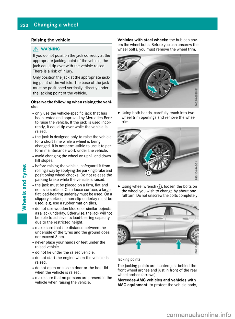
ers the wheel bolts. Before you can unscrew the wheel bolts, you must remove the wheel trim. X
Using both hands, carefully reach into two
wheel trim openings and remove the wheel
trim. X
Using wheel wrench :, loosen the bolts on
the wheel you wish to change by about one
full turn. Do not unscrew the bolts completely. Jacking points
The jacking points are located just behind the
front wheel arches and just in front of the rear
wheel arches (arrows).
Mercedes-AMG vehicles and vehicles with
AMG equipment: to protect the vehicle body,320
Changing a wheelWheels and tyres
Page 327 of 345

R
Only use a spare wheel/emergency spare
wheel briefly if the dimensions are different
to those of the wheel being replaced.
R Do not switch off ESP ®
.
R Have the spare wheel/emergency spare
wheel in question replaced at the nearest
qualified specialist workshop. Make sure
that the wheel/tyre dimensions and tyre
type are correct.
When using an emergency spare wheel or spare wheel of a different size, you must not exceed
the vehicle's maximum design speed of
80 km/h.
You should regularly check the pressure of all
your tyres, including the emergency spare
wheel, particularly prior to long trips, and cor-
rect the pressure as necessary (Y page 313).
The value on the wheel is valid.
Snow chains must not be fitted to emergency
spare wheels. General notes
You can ask for information regarding permitted
emergency spare wheels at a Mercedes-Benz
Service Centre.
An emergency spare wheel may also be fitted
against the direction of rotation. Observe the
time restriction on use as well as the speed lim- itation specified on the emergency spare wheel.
Replace the tyres after six years at the latest,
regardless of wear. This also applies to the
emergency spare wheel.
If you are driving with the emergency spare
wheel fitted, the tyre pressure loss warning sys- tem or the tyre pressure monitor cannot func-
tion reliably. Restart the tyre pressure loss warn-
ing system or tyre pressure monitor only once
the defective wheel has been replaced with a
new wheel.
Vehicles with tyre pressure monitor: after an
emergency spare wheel has been fitted, the sys- tem may still display the tyre pressure of the
removed wheel for a few minutes. The value dis-
played for the position where the emergency
spare wheel is fitted is not the same as the cur- rent tyre pressure of the emergency spare
wheel. Removing the emergency spare wheel
Vehicles with the "Minispare" emergency spare
wheel:
The "Minispare" emergency spare wheel is
secured in emergency spare wheel bag :in the
boot.
X Open the boot lid.
X Release securing straps ;on emergency
spare wheel bag :.
X Remove emergency spare wheel bag :with
the "Minispare" emergency spare wheel.
X Open emergency spare wheel bag :and
remove the "Minispare" emergency spare
wheel.
Observe the instructions and safety notes in the
"Changing a wheel" section (Y page 319).324
Emergency spare wheelWheels and tyres
Page 328 of 345
Information on technical data
i The technical data were determined in
accordance with EU Directives. All data apply
to the vehicle's standard equipment. The data may therefore differ for vehicles with optional
equipment. You can obtain further informa-
tion from a Mercedes-Benz Service Centre. Vehicle electronics
Tampering with the engine electron-
ics
! Only have work carried out on the engine
electronics and its associated parts, such as
control units, sensors, actuating components
and connector leads, at a qualified specialist
workshop. Vehicle components may other-
wise wear more quickly and the vehicle's
operating permit may be invalidated. Retrofitting two-way radios and
mobile phones (RF transmitters) G
WARNING
If RF transmitters are tampered with or not
properly retrofitted, the electromagnetic radi- ation they emit can interfere with the vehicle
electronics. This may jeopardise the opera-
tional safety of the vehicle. There is a risk of an
accident.
You should have all work on electrical and
electronic components carried out at a quali-
fied specialist workshop. G
WARNING
If you operate RF transmitters incorrectly in
the vehicle, the electromagnetic radiation
could interfere with the vehicle electronics,
e.g.:
R if the RF transmitter is not connected to an
exterior aerial
R the exterior aerial has been fitted incor-
rectly or is not a low-reflection type
This could jeopardise the operating safety of
the vehicle. There is a risk of an accident. Have the low-reflection exterior aerial fitted at
a qualified specialist workshop. When oper-
ating RF transmitters in the vehicle, always
connect them to the low-reflection exterior
aerial.
! The operating permit may be invalidated if
the instructions for installation and use of RF
transmitters are not observed.
In particular, the following conditions must be complied with:
R only approved wavebands may be used.
R observe the maximum permissible output
in these wavebands.
R only approved aerial positions may be
used.
Excessive levels of electromagnetic radiation
may cause damage to your health and to the
health of others. The use of an exterior aerial
takes into consideration the scientific discus-
sion surrounding the possible health risk posed
by electromagnetic fields.
Observe the notes on operating mobile phones
(Y page 277).
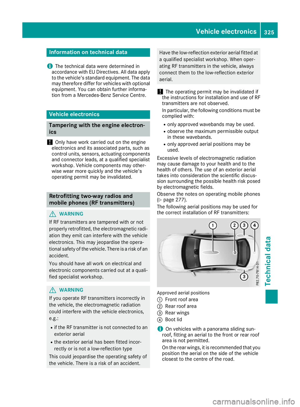
The following aerial positions may be used for
the correct installation of RF transmitters: Approved aerial positions
:
Front roof area
; Rear roof area
= Rear wings
? Boot lid
i On vehicles with a panorama sliding sun-
roof, fitting an aerial to the front or rear roof
area is not permitted.
On the rear wings, it is recommended that you
position the aerial on the side of the vehicle
closest to the centre of the road. Vehicle electronics
325Technical data Z
Page 336 of 345
For the correct mixing ratio, refer to the infor-
mation on the antifreeze reservoir.
i Add washer fluid concentrate, e.g. MB Sum-
merFit or MB WinterFit, to the washer fluid all
year round. Vehicle data
General notes
Please note that for the specified vehicle data:
R the heights specified may vary as a result of:
- tyres
- load
- condition of the suspension
- optional equipment
R optional equipment reduces the maximum
payload
R vehicle-specific weight information can be
found on the vehicle identification plate
(Y page 326)
R for certain countries only: you can find vehi-
cle-specific vehicle data in the COC docu-
ments (CERTIFICATE OF CONFORMITY).
These documents are delivered with your
vehicle Dimensions and weights Missing values were not available at the time of
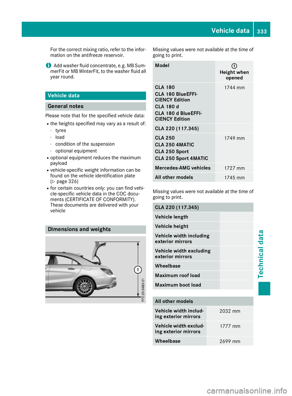
going to print. Model
: :
Height when opened CLA 180
CLA 180 BlueEFFI-
CIENCY Edition
CLA 180 d
CLA 180 d BlueEFFI-
CIENCY Edition
1744 mm
CLA 220 (117.345)
CLA 250
CLA 250 4MATIC
CLA 250 Sport
CLA 250 Sport 4MATIC
1749 mm
Mercedes-AMG vehicles
1727 mm
All other models
1745 mm
Missing values were not available at the time of
going to print. CLA 220 (117.345)
Vehicle length
Vehicle height
Vehicle width including
exterior mirrors
Vehicle width excluding
exterior mirrors
Wheelbase
Maximum roof load
Maximum boot load
All other models
Vehicle width includ-
ing exterior mirrors
2032 mm
Vehicle width exclud-
ing exterior mirrors 1777 mm
Wheelbase
2699 mmVehicle data
333Technical data Z
Page 337 of 345
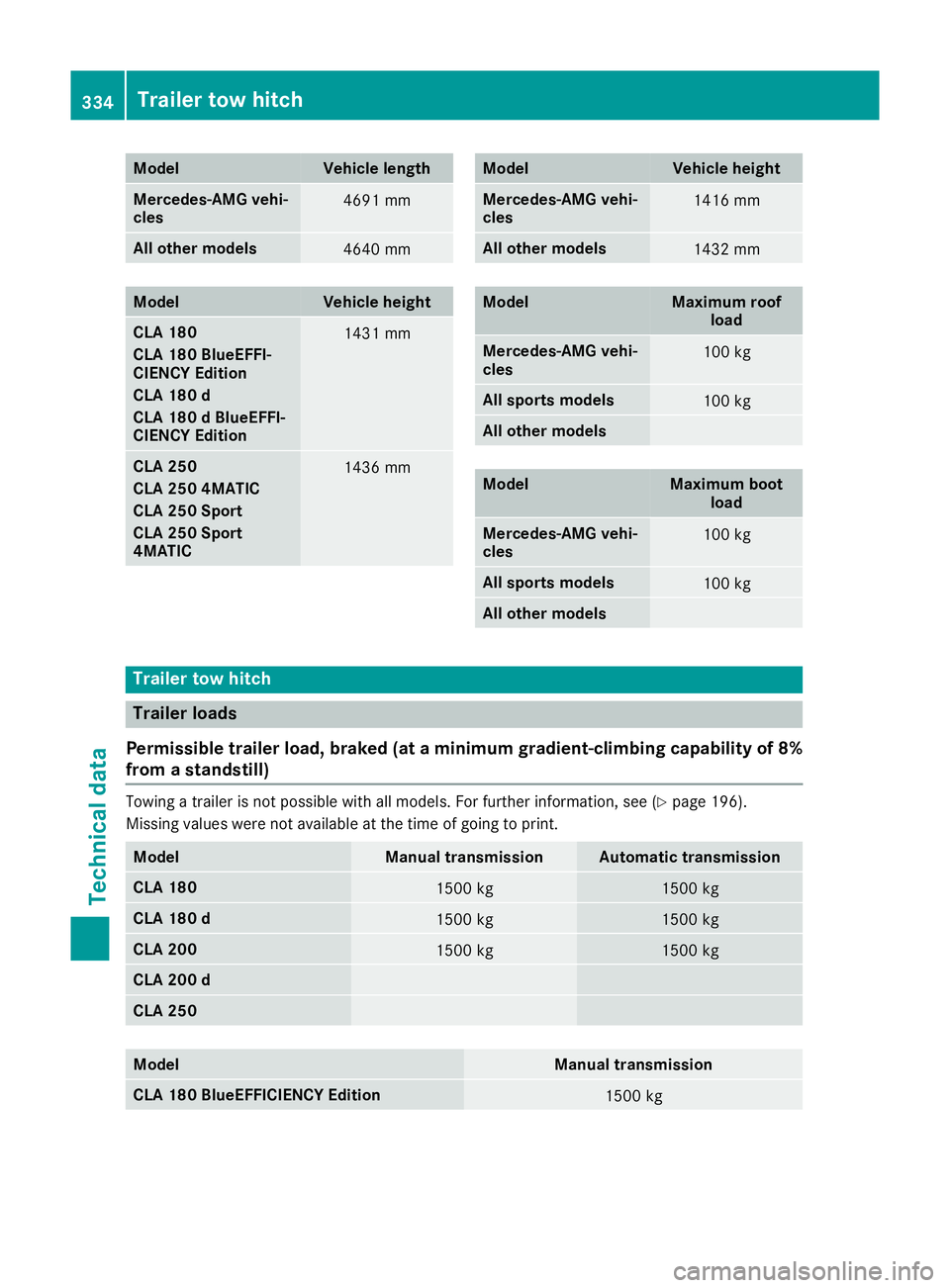
Model Vehicle length
Mercedes-AMG vehi-
cles
4691 mm
All other models
4640 mm
Model Vehicle height
CLA 180
CLA 180 BlueEFFI-
CIENCY Edition
CLA 180 d
CLA 180 d BlueEFFI-
CIENCY Edition
1431 mm
CLA 250
CLA 250 4MATIC
CLA 250 Sport
CLA 250 Sport
4MATIC
1436 mm Model Vehicle height
Mercedes-AMG vehi-
cles
1416 mm
All other models
1432 mm
Model Maximum roof
load Mercedes-AMG vehi-
cles
100 kg
All sports models
100 kg
All other models
Model Maximum boot
load Mercedes-AMG vehi-
cles
100 kg
All sports models
100 kg
All other models
Trailer tow hitch
Trailer loads
Permissible trailer load, braked (at a minimum gradient-climbing capability of 8%
from a standstill) Towing a trailer is not possible with all models. For further information, see (Y
page 196).
Missing values were not available at the time of going to print. Model Manual transmission Automatic transmission
CLA 180
1500 kg 1500 kg
CLA 180 d
1500 kg 1500 kg
CLA 200
1500 kg 1500 kg
CLA 200 d
CLA 250
Model Manual transmission
CLA 180 BlueEFFICIENCY Edition
1500 kg334
Trailer tow hitchTechnical data