2016 MERCEDES-BENZ CLA COUPE clock
[x] Cancel search: clockPage 126 of 345
i
Regardless of the air distribution setting,
airflow is always directed through the side air
vents. The side air vents can only be closed if the adjusters are turned clockwise until they
engage.
Setting the air distribution X Turn the key to position 2in the ignition lock
(Y page 133).
X Press the ÉorË button repeatedly
until the desired symbol appears in the dis-
play. Setting the airflow
Air-conditioning system X
Turn the key to position 2in the ignition lock
(Y page 133).
X To increase or reduce: turn controlAanti-
clockwise or clockwise (Y page 118).
THERMOTRONIC automatic climate
control X
Turn the key to position 2in the ignition lock
(Y page 133).
X To increase or reduce: press theKor
I button. Switching the ZONE function on/off
This function is only available with
THERMOTRONIC automatic climate control.
X To activate: press theábutton.
The indicator lamp in the ábutton lights
up.
The temperature setting for the driver's side
is not adopted for the front-passenger side.
X To deactivate: press theábutton.
The indicator lamp in the ábutton goes
out.
The temperature setting for the driver's side
is adopted for the front-passenger side. Demisting the windscreen
General notes You can use this function to defrost the wind-
screen or to demist the inside of the windscreen
and the side windows.
i You should only select the "Windscreen
demisting" function until the windscreen is
clear again.
Switching the "Windscreen demisting"
function on or off X
Turn the key to position 2in the ignition lock
(Y page 133).
X To activate: press the¬button.
The indicator lamp in the ¬button lights
up.
The climate control system switches to the
following functions:
R high airflow
R high temperature
R air distribution to the windscreen and front
side windows
R air-recirculation mode off
i The "Windscreen demisting" function auto-
matically sets the blower output to the opti-
mum demisting effect. As a result, the airflow may increase or decrease automatically after
the ¬ button is pressed.
i You can adjust the blower output manually
while the "Windscreen demisting" function is
in operation:
R Air-conditioning system: turn airflow con-
trol Aanti-clockwise or clockwise
(Y page 118).
R THERMOTRONIC automatic climate con-
trol: press the óorô button.
X To deactivate: press the¬button.
The indicator lamp in the ¬button goes
out. The previous settings are reactivated.
Air-recirculation mode remains deactivated.
or
X THERMOTRONIC automatic climate control:
press the Ãbutton.
The indicator lamp in the ¬button goes
out. Airflow and air distribution are set to
automatic mode. Operating the climate control system
123Climate control
Page 127 of 345

or
X Air-conditioning system: turn temperature
control :anti-clockwise or clockwise
(Y page 118).
THERMOTRONIC automatic climate control:
turn temperature control :orE anti-clock-
wise or clockwise (Y page 119).Demisting the windows
Windows misted up on the inside Air-conditioning system
X Activate the ¿"Cooling with air dehumid-
ification" function.
X If the windows continue to mist up, activate
the ¬ "Windscreen demisting" function.
i You should only select this setting until the
windscreen is clear again.
THERMOTRONIC automatic climate con-
trol
X Activate the ¿"Cooling with air dehumid-
ification" function.
X Activate automatic mode Ã.
X If the windows continue to mist up, activate
the ¬ "Windscreen demisting" function.
i You should only select this setting until the
windscreen is clear again. Windows misted up on the outside X
Activate the windscreen wipers.
X Set the air distribution to PorO.
i You should only select this setting until the
windscreen is clear again. Rear window heating
General notes The rear window heating has a high current
draw. You should therefore switch it off as soon
as the window is clear. The rear window heating otherwise switches off automatically after sev-
eral minutes.
If the battery voltage is too low, the rear window
heating may switch off.
Activating/deactivating X
Turn the key to position 2in the ignition lock
(Y page 133).
X Press the ¤button.
The indicator lamp in the ¤button lights
up or goes out.
Problems with the rear window heating Problem
Possible causes/consequences and
M MSolutions The rear window heating
has switched off prema-
turely or cannot be
switched on. The battery has not been sufficiently charged.
X Switch off any consumers that are not required, e.g. reading lamps,
interior lighting or the seat heating.
When the battery is sufficiently charged, the rear window heating
can be switched on again. Activating/deactivating air-recircula-
tion mode
General notes You can deactivate the flow of fresh air tempo-
rarily if unpleasant odours are entering the vehi-
cle from outside. The air already inside the vehi- cle will then be recirculated. If you activate air-recirculation mode, the win-
dows can mist up more quickly, particularly at
low temperatures. Use air-recirculation mode
only briefly to prevent the windows from misting
up.
The operation of air-recirculation mode is the
same for all control panels. 124
Operating the climate control systemClimate control
Page 134 of 345
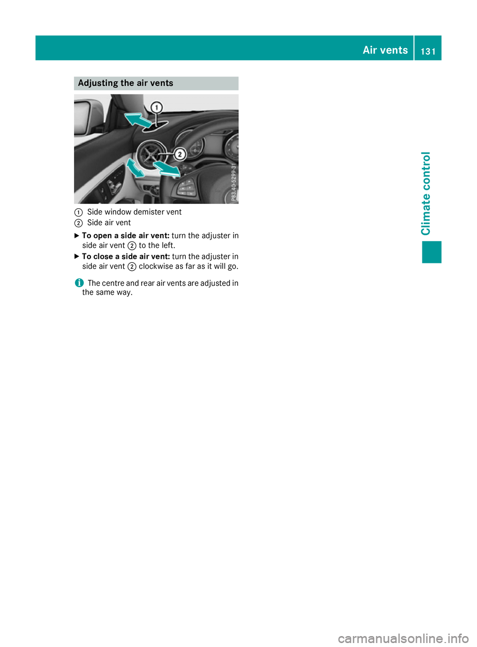
Adjusting the air vents
:
Side window demister vent
; Side air vent
X To open a side air vent: turn the adjuster in
side air vent ;to the left.
X To close a side air vent: turn the adjuster in
side air vent ;clockwise as far as it will go.
i The centre and rear air vents are adjusted in
the same way. Air vents
131Climate cont rol Z
Page 157 of 345
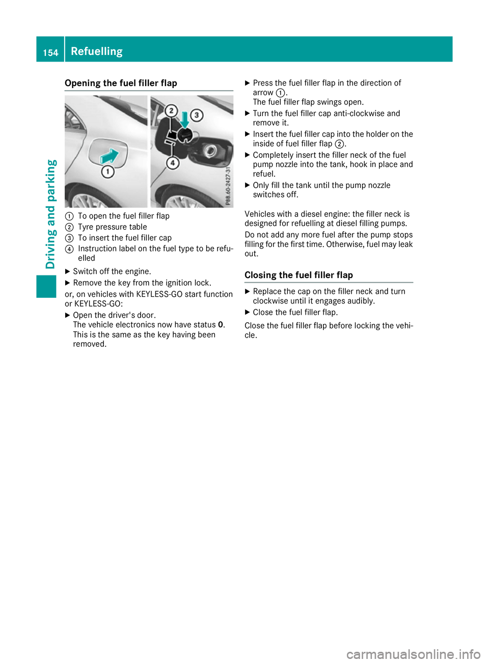
Opening the fuel filler flap
:
To open the fuel filler flap
; Tyre pressure table
= To insert the fuel filler cap
? Instruction label on the fuel type to be refu-
elled
X Switch off the engine.
X Remove the key from the ignition lock.
or, on vehicles with KEYLESS-GO start function
or KEYLESS‑GO: X Open the driver's door.
The vehicle electronics now have status 0.
This is the same as the key having been
removed. X
Press the fuel filler flap in the direction of
arrow :.
The fuel filler flap swings open.
X Turn the fuel filler cap anti-clockwise and
remove it.
X Insert the fuel filler cap into the holder on the
inside of fuel filler flap ;.
X Completely insert the filler neck of the fuel
pump nozzle into the tank, hook in place and refuel.
X Only fill the tank until the pump nozzle
switches off.
Vehicles with a diesel engine: the filler neck is
designed for refuelling at diesel filling pumps.
Do not add any more fuel after the pump stops
filling for the first time. Otherwise, fuel may leak out.
Closing the fuel filler flap X
Replace the cap on the filler neck and turn
clockwise until it engages audibly.
X Close the fuel filler flap.
Close the fuel filler flap before locking the vehi-
cle. 154
RefuellingDriving and parking
Page 200 of 345
Folding out the ball coupling
Folding out the ball coupling G
WARNING
If the ball coupling is not correctly engaged,
the trailer can detach. There is a risk of an
accident.
Always engage the ball coupling as described. G
WARNING
If you release the ball coupling or it does not
engage correctly when folding in, it will swing out. Within pivoting range of the ball coupling,
there is an increased risk of an accident and
injury.
Only release the ball coupling if the pivoting
range is unobstructed. Always make sure that the ball coupling engages when folding in.
Before you can tow a trailer with your vehicle,
you must fold out the ball coupling.
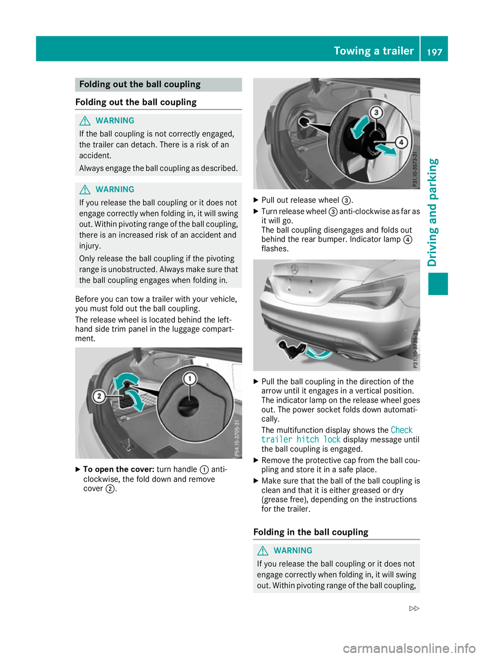
The release wheel is located behind the left-
hand side trim panel in the luggage compart-
ment. X
To open the cover: turn handle:anti-
clockwise, the fold down and remove
cover ;. X
Pull out release wheel =.
X Turn release wheel =anti-clockwise as far as
it will go.
The ball coupling disengages and folds out
behind the rear bumper. Indicator lamp ?
flashes. X
Pull the ball coupling in the direction of the
arrow until it engages in a vertical position.
The indicator lamp on the release wheel goes
out. The power socket folds down automati-
cally.
The multifunction display shows the Check Check
trailer hitch lock
trailer hitch lock display message until
the ball coupling is engaged.
X Remove the protective cap from the ball cou-
pling and store it in a safe place.
X Make sure that the ball of the ball coupling is
clean and that it is either greased or dry
(grease free), depending on the instructions
for the trailer.
Folding in the ball coupling G
WARNING
If you release the ball coupling or it does not
engage correctly when folding in, it will swing out. Within pivoting range of the ball coupling, Towing a trailer
197Driving and parking
Z
Page 201 of 345
there is an increased risk of an accident and
injury.
Only release the ball coupling if the pivoting
range is unobstructed. Always make sure that the ball coupling engages when folding in.
i Fold the ball coupling in if you are not using
the trailer tow hitch.
X Make sure that the vehicle is stationary and
the trailer cables are disconnected.
X Place the protective cap on the ball coupling.
i The release wheel is located behind the left-
hand side trim panel in the luggage compart- ment.
X To open the cover: turn handle:anti-
clockwise, then fold down and remove
cover ;.
X Pull out release wheel =.
X Turn release wheel =anti-clockwise as far as
it will go.
The ball coupling disengages and folds out
behind the rear bumper. Indicator lamp ?
flashes.
X Press the ball coupling until it engages audibly
behind the bumper.
The indicator lamp on the release knob and
the message in the multifunction display go
out. Coupling up a trailer
X Make sure that the transmission is in position
P.
X Apply the electric parking brake.
X Position the trailer horizontally behind the
vehicle.
X Couple up the trailer.
X Establish the electric connection between the
vehicle and the trailer.
X Check that the trailer lighting system is work-
ing.
A connected trailer is only recognised when
the electrical connection is established cor-
rectly and when the lighting system is working
properly. The function of other systems, such
as ESP ®
or PARKTRONIC also depends on
this. Uncoupling a trailer
G
WARNING
If you uncouple a trailer with an engaged over- run brake, you could trap your hand between
the vehicle and the trailer drawbar. This poses a risk of injury.
Do not uncouple a trailer with an engaged
overrun brake.
! Do not disconnect a trailer with an engaged
overrun brake. Otherwise, your vehicle could
be damaged by the rebounding of the overrun brake.
! Remove the installed adapter cable before
folding in the ball coupling. Otherwise, dam-
age may occur to the rear bumper and the
adapter cable.
X Make sure that the transmission is in position
P.
X Apply the electric parking brake.
X Secure the trailer against rolling away.
X Remove the trailer cable and decouple the
trailer. Trailer power supply
! You can connect accessories to the perma-
nent power supply up to a maximum of 240 W.
You cannot charge a trailer battery using the
power supply.
When it leaves the factory, your vehicle's trailer
socket is equipped with a permanent power
supply and a power supply that is switched on
via the ignition lock.
The permanent power supply is supplied via
trailer socket pin 9.
The power supply that is switched on via the
ignition lock is supplied via trailer socket pin 10.
The trailer's permanent power supply is
switched off in the event of low vehicle supply
voltage and after six hours at the latest.
You can find more information about fitting the
trailer electrics at a qualified specialist work-
shop.
X To switch the connected power supply on
or off: turn the key to position 2or0respec-
tively (Y page 133). 198
Towing a trailerDriving an
d parking
Page 202 of 345
Failure check for LEDs
If LED lamps are fitted in the trailer, a malfunc-
tion message may appear in the multifunction
display even if there is no fault. The reason for
the error message may be that the current has
fallen below the minimum of 50 mA.
To ensure reliable operation of the failure indi-
cator, each LED chain in the trailer lighting must
be guaranteed a minimum current of 50 mA. Trailer with 7-pin connector
General notes Trailer with 7-pin connector:
you can connect
to the 13-pin socket on the ball coupling using
an adapter or, if necessary, an adapter cable.
Both can be obtained at a qualified specialist
workshop.
Fitting the adapter !
Make sure that there is sufficient cable play
so that the cable cannot become detached
when cornering.
! Remove the installed adapter cable before
folding in the ball coupling. Otherwise, dam-
age may occur to the rear bumper and the
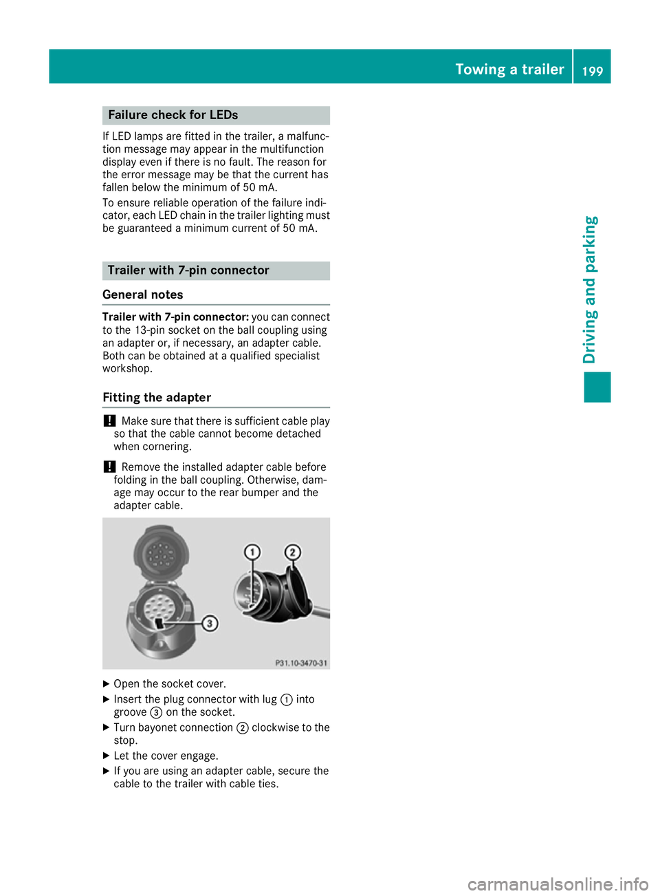
adapter cable. X
Open the socket cover.
X Insert the plug connector with lug :into
groove =on the socket.
X Turn bayonet connection ;clockwise to the
stop.
X Let the cover engage.
X If you are using an adapter cable, secure the
cable to the trailer with cable ties. Towing a trailer
199Driving and parking Z
Page 203 of 345
Important safety notes
G
WARNING
Operating the integrated information systems and communications equipment in the vehicle
while driving will distract you from traffic con-
ditions. You could then lose control of the
vehicle. There is a risk of an accident.
Only operate these devices if road traffic con-
ditions permit. If you are unsure about the
surrounding conditions, pull over to a safe
location and make entries only while the vehi-
cle is stationary.
You must observe the legal requirements for the country in which you are currently driving whenoperating the on-board computer. G
WARNING
If the instrument cluster has failed or mal-
functioned, you may not recognise function
restrictions relevant to safety. The operating
safety of your vehicle may be impaired. There is a risk of an accident.
Drive on carefully. Have the vehicle checked
at a qualified specialist workshop immedi-
ately.
The on-board computer only shows messages or warnings from certain systems in the multifunc-tion display. You should therefore make sure
your vehicle is operating safely at all times.
If the operating safety of your vehicle is
impaired, park the vehicle safely as soon as pos- sible. Contact a qualified specialist workshop.
For an overview, see the instrument panel illus-
tration (Y page 32). Displays and operation
Instrument cluster lighting
The light sensor in the instrument cluster auto-
matically controls the brightness of the multi-
function display. In daylight, the displays in the
instrument cluster are not illuminated.
The lighting in the instrument cluster, in the dis- plays and the controls in the vehicle interior can
be adjusted using the brightness control knob. The brightness control knob is located on the
bottom left of the instrument cluster
(Y
page 32).
X Turn the brightness control knob clockwise or
anti-clockwise.
If the light switch is set to the Ã,Tor
L position, the brightness is dependent
upon the brightness of the ambient light. Speedometer with segments
The speedometer is divided into segments on
vehicles with Distance Pilot DISTRONIC.
The segments in the speedometer indicate
which speed range is available. R Variable speed limiter is activated
(Y page 165):
The segments light up from the start of the
scale to the selected speed limitation.
R Distance Pilot DISTRONIC is activated
(Y page 167):
One or two segments in the stored speed
range light up.
R Distance Pilot DISTRONIC detects a vehicle in
front moving more slowly than the stored
speed:
The segments between the speed of the vehi- cle in front and the stored speed light up. Rev counter
! Do not drive in the overrevving range. Doing
so will damage the engine.
The red band in the rev counter indicates the
engine's overrevving range.
The engine is limited within a range to protect
the engine when the red band is reached. Outside temperature display
You should pay special attention to road condi-
tions when temperatures are around freezing
point.
Bear in mind that the outside temperature dis-
play indicates the measured air temperature
and not the road surface temperature.
The outside temperature display is in the multi-
function display (Y page 202).200
Displays and operationOn-board computer and displays