2016 MERCEDES-BENZ AMG GT S phone
[x] Cancel search: phonePage 222 of 290

Vehicle remote closing
The vehicle remote-closing feature can be used
when you have forgotten to lock the vehicle and
you are no longer nearby.
The vehicle can then be locked by the Mercedes-
Benz Customer Assistance Center.
The vehicle can be immediately remotely locked
within four days of the ignition being turned off.
After this time, remote closing may be delayed
by 15 to 60 minutes. After 30 days the vehicle
can no longer be locked remotely.
The vehicle remote closing feature is available if
the relevant mobile phone network is available
and a data connection is possible.
XContact the following service hotlines:
Mercedes-Benz Customer Assistance Center
at 1-800-FOR-MERCedes (1-800-367-6372)
or 1-866-990-9007
You will be asked for your password.
The next time you are inside the vehicle and you
switch on the ignition, the Doors Locked
Remotelymessage appears in the multifunction
display.
Alternatively, the vehicle can be locked via:
Rthe Internet, under the "Owners Online" sec-
tion
Rthe telephone application (e .g. for iPhone®,
Android)
To do this, you will need your identification num-
ber and password.
Stolen vehicle recovery service
If your vehicle has been stolen:
XNotify the police.
The police will issue a numbered incident
report.
XThis number will be forwarded to the
Mercedes-Benz Customer Assistance Center
together with your PIN.
The Mercedes-Benz Customer Assistance
Center then tries to locate the system. The
Mercedes-Benz Customer Assistance Center
contacts you and the local law enforcement
agency if the vehicle is located.
However, only the law enforcement agency is
informed of the location of the vehicle.
If the anti-theft alarm system is activated for
longer than 30 seconds, the Mercedes-Benz
Customer Assistance Center is automatically
notified.
Vehicle Health Check
With the Vehicle Health Check, the Customer
Assistance Center can provide improved sup-
port for problems with your vehicle. During an
existing call, vehicle data is transferred to the
Customer Assistance Center.
The customer service representative can use
the received data to decide what kind of assis-
tance is required. You are then, for example,
guided to the nearest authorized Mercedes-
Benz Center or a recovery vehicle is called.
If vehicle data needs to be transferred during an
MB Info call or a Roadside Assistance call, this is
initiated by the Customer Assistance Center.
The Roadside Assistance Connected
mes-
sage appears in the display. If the Vehicle Health
Check can be started, the Request
forVehi‐cle Diagnostics Received Start vehi‐cle diagnostics?message appears in the
display.
XPress the Yesbutton to confirm the message.
XWhen the Vehicle Diagnostics PleaseStart Ignitionmessage appears: turn the
SmartKey to position 2in the ignition lock
(
Ypage 103).
XIf the Please follow the instructionsreceivedbyphoneandmoveyourvehi‐cle to a safe position.message
appears: please follow the instructions
received by phone and move your vehicle to a
safe position.
The message in the display disappears.
The vehicle operating state check begins.
During this procedure, you will see the Vehi‐
cle Diagnostics Activemessage.
If you select Cancel
, the Vehicle Health
Check is canceled completely.
When the check is complete, the Sending
vehicle diagnostics data. (Voice con‐nection may be interrupted duringdatatransfer)message appears. The vehicle
data can now be sent.
XPress the OKbutton to confirm the message.
The voice connection with the Customer
Assistance Center is terminated.
The Vehicle Diagnostics: Transfer‐
ring Data...message appears.
The vehicle data is sent to the Customer
Assistance Center.
Depending on what the customer service rep-
resentative agreed with you, the voice connec-
220Features
Stowage and features
Page 223 of 290

tion is re-established after the transfer is com-
plete. If necessary, you will be contacted at a
later time by another means, e.g. by e-mail or
phone.
Another function of the Vehicle Health Check is
the transfer of service data to the Customer
Assistance Center. If a service is due, the display
shows a message to this effect together with
information about any special offers at your
workshop.
This information can also be called up under
"Owners Online" at http://www.mbusa.com.
Information on the data stored in the vehicle
(
Ypage 26).
Information on Roadside Assistance
(
Ypage 23).
Downloading routes
Downloading routes allows you to transfer and
save predefined routes in the navigation sys-
tem.
A route can be prepared and sent by either a
customer service representative or under "Own-
ers Online" at http://www.mbusa.com.
Each route can include up to four way points.
Once a route has been received by the naviga-
tion system, you will see the External
desti‐nation ICON_POI_Category Name_1 hasbeen saved to "Previous destina‐tions". Would you like to start navi‐gation?message on the multimedia system
display.
The route is saved.
XTo start route guidance: selectYes.
An overview of the route is shown in the dis-
play.
If you select No
, the saved route can be called
up later in the navigation menu.
XSelect Start.
Starting route guidance.
Downloaded and saved routes can be called up
again.
You can find further information in the separate
multimedia system operating instructions.
Speed alert
You can define the upper speed limit, which
must not be exceeded by the vehicle.
If this selected speed is exceeded by the vehicle,
a message will be sent to the Customer Assis- tance Center. The Customer Assistance Center
then forwards this information to you.
You can select the way in which you receive this
information beforehand. Possible options
include text message, e-mail or an automated
call.
The data you receive contains the following
information:
Rthe location where the speed limit was excee-
ded
Rthe time at which the speed limit was excee-
ded
Rthe selected speed limit which was exceeded
Geo fencing
Geo fencing allows you to select areas which the
vehicle should not enter or leave. You will be
informed if the vehicle crosses the boundaries
of the selected areas. You can select the way in
which you receive this information beforehand.
Possible options include text message, e-mail or an automated call.
The area can be determined as either a circle or
a polygon with a maximum of ten corners. You
can specify up to ten areas simultaneously. Dif-
ferent settings are possible for each area.
These settings can be called up under "Owners
Online" at http://www.mbusa.com.
Alternatively, you can trigger an MB Info call and
inform the customer service representative that
you wish to activate geo fencing.
Currently inactive areas can be activated by text
message.
Triggering the vehicle alarm
With this function, you can trigger the vehicle's
panic alarm via text message. An alarm sounds
and the exterior lighting flashes. Depending on
the setting, the panic alarm lasts five or ten sec-onds. Afterwards, the alarm switches off.
Features221
Stowag ean d features
Z
Page 225 of 290

Problems with the rear spoiler
ProblemPossible causes/consequences andMSolutions
The rear spoiler stops
before reaching the end
position when retracting
manually.You have opened the tailgate while manually retracting the rear
spoiler.
XClose the tailgate.
The rear spoiler extends or, if you press and hold the ¬button,
continues retracting.
The rear spoiler stops
before reaching the end
position when retract-
ing/extending manually.You have switched off the ignition.
XSwitch the ignition back on.
XPress the ¬button.
The rear spoiler extends/retracts.
The rear spoiler cannot
be retracted again after
manually extending it.You have opened the tailgate while manually extending the rear
spoiler.
XClose the tailgate.
The rear spoiler does not
extend or retract auto-
matically.The rear spoiler's movement is blocked, e.g. by an object jammed
between the body and the rear spoiler.
XRemove the object.
Garage door opener
General notes
The HomeLink®garage door opener integrated
in the rear-view mirror allows you to operate up
to three different door and gate systems.
Use the integrated garage door opener only on
garage doors that:
Rhave safety stop and reverse features and
Rmeet current U.S. federal safety standards
Once programed, the integrated garage door
opener in the rear-view mirror will assume the
function of the garage door system's remote
control. Please also read the operating instruc-
tions for the garage door system.
When programming a garage door opener, park
the vehicle outside the garage. Do not run the
engine while programming.
Certain garage door drives are incompatible
with the integrated garage door opener. If you
have difficulty programing the integrated garage door opener, contact an authorized Mercedes-
Benz Center. Alternatively, you can call the following tele-
phone assistance services:
RUSA:
Mercedes-Benz Customer Assistance
Center at 1-800-FOR-MERCedes
RCanada: Customer Service at
1-800-387-0100
RHomeLink®hotline 1-800-355-3515 (free of
charge)
More information on HomeLink
®and/or com-
patible products is also available online at
http://www.homelink.com.
Notes on the declaration of conformity
(
Ypage 24).
USA: FCC ID: CB2HMIHL4
Canada: IC: 279B-HMIHL4
Important safety notes
GWARNING
When you operate or program the garage door
with the integrated garage door opener, per-
sons in the range of movement of the garage
door can become trapped or struck by the
garage door. There is a risk of injury.
When using the integrated garage door
opener, always make sure that nobody is
Features223
Stowage and features
Z
Page 232 of 290
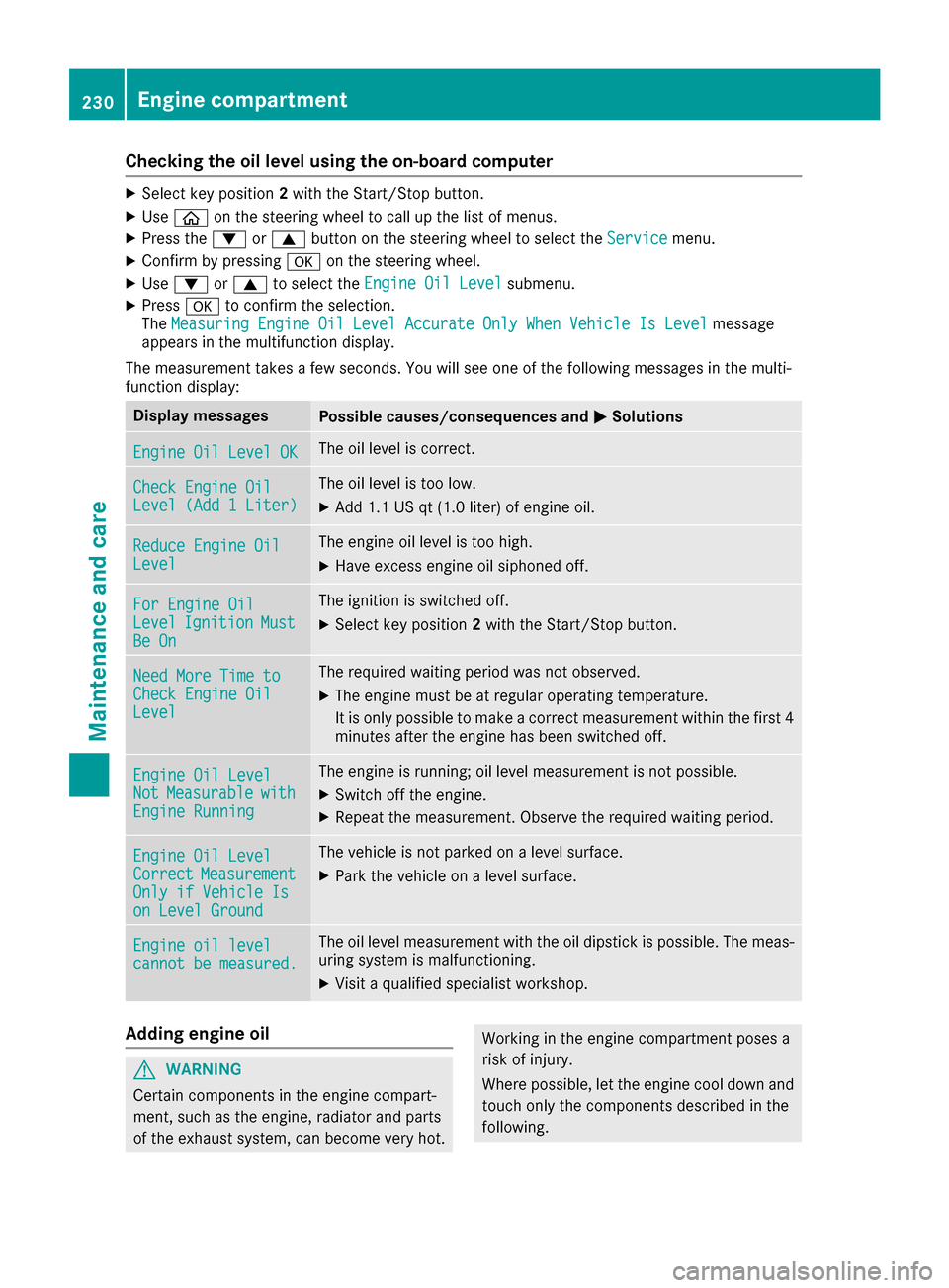
Checking the oil level using the on-board computer
XSelect key position2with the Start/Stop button.
XUse ò on the steering wheel to call up the list of menus.
XPress the :or9 button on the steering wheel to select the Servicemenu.
XConfirm by pressingaon the steering wheel.
XUse: or9 to select the Engine Oil Levelsubmenu.
XPressato confirm the selection.
The Measuring Engine Oil Level Accurate Only When Vehicle Is Levelmessage
appears in the multifunction display.
The measurement takes a few seconds. You will see one of the following messages in the multi-
function display:
Display messagesPossible causes/consequences and MSolutions
Engine Oil Level OKThe oil level is correct.
Check Engine OilLevel (Add 1 Liter)
The oil level is too low.
XAdd 1.1 US qt (1.0 liter) of engine oil.
Reduce Engine OilLevel
The engine oil level is too high.
XHave excess engine oil siphoned off.
For Engine OilLevelIgnitionMustBe On
The ignition is switched off.
XSelect key position2with the Start/Stop button.
Need More Time toCheck Engine OilLevel
The required waiting period was not observed.
XThe engine must be at regular operating temperature.
It is only possible to make a correct measurement within the first 4
minutes after the engine has been switched off.
Engine Oil LevelNotMeasurablewithEngine Running
The engine is running; oil level measurement is not possible.
XSwitch off the engine.
XRepeat the measurement. Observe the required waiting period.
Engine Oil LevelCorrectMeasurementOnly if Vehicle Ison Level Ground
The vehicle is not parked on a level surface.
XPark the vehicle on a level surface.
Engine oil levelcannot be measured.
The oil level measurement with the oil dipstick is possible. The meas-
uring system is malfunctioning.
XVisit a qualified specialist workshop.
Adding engine oil
GWARNING
Certain components in the engine compart-
ment, such as the engine, radiator and parts
of the exhaust system, can become very hot.
Working in the engine compartment poses a
risk of injury.
Where possible, let the engine cool down and touch only the components described in the
following.
230Engine compartment
Maintenance and care
Page 233 of 290
GWARNING
If engine oil comes into contact with hot com- ponents in the engine compartment, it may
ignite. There is a risk of fire and injury.
Make sure that engine oil is not spilled next to
the filler neck. Let the engine cool down and
thoroughly clean the engine oil off the com-
ponents before starting the engine.
HEnvironmental note
When adding oil, take care not to spill any. If
oil enters the soil or waterways, it is harmful to
the environment.
!Only use engine oils and oil filters that have
been approved for vehicles with a service sys-
tem. You can obtain a list of the engine oils
and oil filters tested and approved in accord- ance with the Mercedes-Benz Specifications
for Service Products at any Mercedes-Benz
Service center.
Damage to the engine or exhaust system is
caused by the following:
Rusing engine oils and oil filters that have notbeen specifically approved for the service
system
Rreplacing engine oil and oil filters after the
interval for replacement specified by the
service system has been exceeded
Rusing engine oil additives.
!Do not add too much oil. If the oil level is
above the "max" mark on the dipstick, too
much oil has been added. This can lead to
damage to the engine or the catalytic con-
verter. Have excess oil siphoned off.
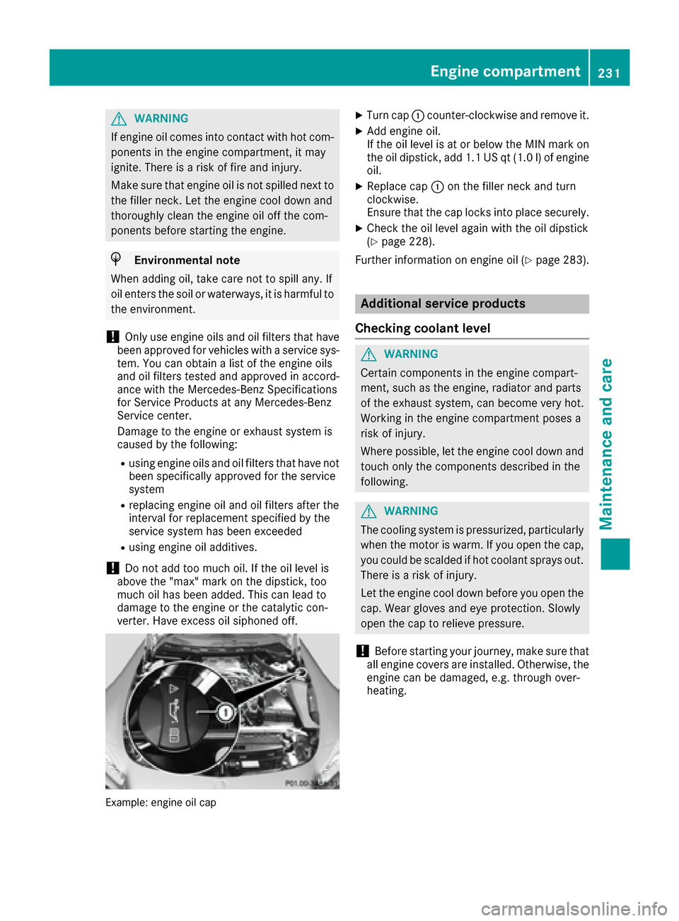
Example: engine oil cap
XTurn cap :counter-clockwise and remove it.
XAdd engine oil.
If the oil level is at or below the MIN mark on
the oil dipstick, add 1.1 US qt (1.0 l) of engine
oil.
XReplace cap :on the filler neck and turn
clockwise.
Ensure that the cap locks into place securely.
XCheck the oil level again with the oil dipstick
(Ypage 228).
Further information on engine oil (
Ypage 283).
Additional service products
Checking coolant level
GWARNING
Certain components in the engine compart-
ment, such as the engine, radiator and parts
of the exhaust system, can become very hot.
Working in the engine compartment poses a
risk of injury.
Where possible, let the engine cool down and touch only the components described in the
following.
GWARNING
The cooling system is pressurized, particularly
when the motor is warm. If you open the cap,
you could be scalded if hot coolant sprays out.
There is a risk of injury.
Let the engine cool down before you open the
cap. Wear gloves and eye protection. Slowly
open the cap to relieve pressure.
!Before starting your journey, make sure that
all engine covers are installed. Otherwise, the
engine can be damaged, e.g. through over-
heating.
Engine compartment231
Maintenance and care
Z
Page 263 of 290

bility to maintain correct tire pressure, even ifunderinflation has not reached the level to
trigger illumination of the TPMS low tire pres-
sure telltale.
Your vehicle has also been equipped with a
TPMS malfunction indicator to indicate when
the system is not operating properly. The
TPMS malfunction indicator is combined with
the low tire pressure telltale. When the sys-
tem detects a malfunction, the warning lamp
will flash for approximately a minute and thenremain continuously illuminated. This
sequence will be repeated every time the vehi-
cle is started as long as the malfunction
exists. When the malfunction indicator is illu-
minated, the system may not be able to detect
or signal low tire pressure as intended.
TPMS malfunctions may occur for a variety of
reasons, including the installation of incom-
patible replacement or alternate tires or
wheels on the vehicle that prevent the TPMS
from functioning properly. Always check the
TPMS malfunction telltale after replacing one
or more tires or wheels on your vehicle to
ensure that the replacement or alternate Tires
and wheels allow the TPMS to continue to
function properly.
It is the driver's responsibility to set the tire
pressure to that recommended for cold tires
which is suitable for the operating situation
(
Ypage 257). Note that the correct tire pressure
for the current operating situation must first be
taught-in to the tire pressure monitor. If there is
a substantial loss of pressure, the warning
threshold for the warning message is aligned to
the reference values taught-in. Restart the tire
pressure monitor after adjusting the pressure of
the cold tires (
Ypage 262). The current pres-
sures are saved as new reference values. As a
result, a warning message will appear if the tire
pressure drops significantly.
The tire pressure monitor does not warn you of
an incorrectly set tire pressure. Observe the
notes on the recommended tire pressure
(
Ypage 257).
The tire pressure monitor is n
ot able to warn you
of a sudden loss of pressure, e.g. if the tire is
penetrated by a foreign object. In the event of a
sudden loss of pressure, bring the vehicle to a halt by braking carefully. Avoid abrupt steering
movements.
The tire pressure monitor has a yellow warning
lamp in the instrument cluster for indicating
pressure loss or a malfunction. Whether the
warning lamp flashes or lights up indicates
whether a tire pressure is too low or the tire
pressure monitor is malfunctioning:
Rif the warning lamp is lit continuously, the tire
pressure on one or more tires is significantly
too low. The tire pressure monitor is not mal- functioning.
Rif the warning lamp flashes for around a
minute and then remains lit constantly, the
tire pressure monitor is malfunctioning.
In addition to the warning lamp, a message
appears in the multifunction display. Observe
the information on display messages
(
Ypage 183).
It may take up to ten minutes for a malfunction
of the tire pressure monitor to be indicated. A
malfunction will be indicated by the tire pres-
sure warning lamp flashing for approximately
one minute and then remaining lit. When the
malfunction has been rectified, the tire pressure
warning lamp goes out after a few minutes of
driving.
The tire pressure values indicated by the on-
board computer may differ from those meas-
ured at a gas station with a pressure gauge. The
tire pressures shown by the on-board computer
refer to those measured at sea level. At high
altitudes, the tire pressure values indicated by a pressure gauge are higher than those shown by
the on-board computer. In this case, do not
reduce the tire pressures.
The operation of the tire pressure monitor can
be affected by interference from radio transmit-
ting equipment (e.g. radio headphones, two-way
radios) that may be being operated in or near the
vehicle.
Checking the tire pressure electroni-
cally
XSwitch on the ignition (Ypage 103).
XUse ò on the steering wheel to call up the
list of menus.
XPress 9or: on the steering wheel to
select the Servicemenu.
XPress theabutton.
Tire pressure261
Wheels and tires
Z
Page 281 of 290

Information regarding technical data
i
The dat astate dher especifically refers to a
vehicl ewit hstandard equipment. Consult an
authorize dMercedes-Ben zCente rfor th e
dat afor all vehicl evariants and trim levels.
Vehicle electronics
Tampering with the engine electron-
ics
!
Only hav ewor kcarried out on th eengin e
electronics and it sassociated parts, suc has
control units, sensors, actuating component s
and connecto rleads ,at aqualified specialist
workshop. Vehicl ecomponent smay other -
wise wear mor equickly and th evehicle's
operating permit may be invalidated.
Retrofitting two-way radios and
mobile phones (RF transmitters)
GWARNIN G
The electromagneti cradiation from modifie d
or incorrectl yretrofitte dRF-transmitters can
interfere wit hth evehicl eelectronics .This can
compromise th eoperational safet yof th e
vehicle. Ther eis aris kof an accident.
You should hav eall wor kto electrical and
electronic equipmen tcarried out at aqualified
specialist workshop.
GWARNIN G
The electromagneti cradiation from incor-
rectl yoperate dRF transmitters can interfere
wit hth evehicl eelectronics ,for example:
Rif th eRF transmitte ris no tconnecte dwit h
an exterio rantenna
Rth eexterio rantenna has been installed
incorrectl yor is no t alow-reflection typ e
This can compromise th eoperational safet y
of th evehicle. Ther eis aris kof an accident.
Hav eth elow-reflection exterio rantenna
mounte dat aqualified specialist workshop.
When operating RF transmitters in th evehi-
cle ,always connec tthem wit hth elow-reflec -
tion exterio rantenna.
!The operating permit may be invalidated if
th einstruction sfor installation and use of RF
transmitters are no tobserved.
In particular, th efollowin gcondition smust be
complied with:
Ronly approve dwavebands may be used.
Rcomplianc ewit hth emaximum permissible
output in these wavebands is required.
Ronly approve dantenna position smay be
used.
Excessiv elevels of electromagneti cradiation
may caus edamag eto your healt hand th ehealt h
of others. Using an exterio rantenna takes int o
accoun tcurren tscientific discussion srelating
to th epossible healt hhazards that may result
from electromagneti cfields.
Antenn aposition s
:
Rear fender
On th erear fenders, it is recommended to posi-
tion th eantenna on th eside of th evehicl eclos-
est to th ecenter of th eroad .
Use th eTechnical Specification ISO/TS 2160 9
when retrofitting RF transmitters (Road Vehicles
- EM Cguidelines for installation of aftermarket
radi ofrequency transmitting equipment) .
Observ eth elegal requirements for accessory
parts.
If your vehicl ehas installation sfor two-way radi o
equipment, use th epower suppl yor antenna
connection sintended for use wit hth ebasic wir-
ing .Be sur eto observ eth emanufacturer' sSup -
plemen twhen installing.
Deviation swit hrespec tto frequency bands,
maximum transmission output sor antenna
position smust be approve dby Mercedes-Benz.
Vehicle electronics279
Technical data
Z
Page 282 of 290
The maximum transmission output (PEAK) at the
base of the antenna must not exceed the fol-
lowing values:
Frequency bandMaximum
transmission output
Short wave
3 - 54 MHz100 W
4 m waveband
74 - 88 MHz30 W
2 m waveband
144 - 174 MHz50 W
Trunked radio system/
Tetra
380 - 460 MHz10 W
70 cm waveband
400 - 460 MHz35 W
Mobile communications
(2G/3G/4G)10 W
The following can be used in the vehicle without
restrictions:
RRF transmitters with a maximum transmis-
sion output of up to 100 mW
RRF transmitters with transmitter frequencies
in the 380 - 410 MHz frequency band and a
maximum transmission output of up to 2 W
(trunked radio system/Tetra)
RMobile phones (2G/3G/4G)
There is no restriction for antenna positions on
the outside of the vehicle for the following fre-
quency bands:
RTrunked radio system/Tetra
R70 cm waveband
R2G/3G/4G
Identification plates
Vehicle identification plate with vehi-
cle identification number (VIN)
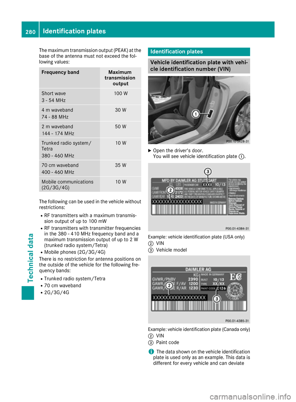
XOpen the driver's door.
You will see vehicle identification plate :.
Example: vehicle identification plate (USA only)
;
VIN
=Vehicle model
Example: vehicle identification plate (Canada only)
;
VIN
=Paint code
iThe data shown on the vehicle identification
plate is used only as an example. This data is
different for every vehicle and can deviate
280Identification plates
Technical data