2016 MERCEDES-BENZ AMG GT ROADSTER lock
[x] Cancel search: lockPage 257 of 289
R
It is important that you observe the described order of the battery terminals when connecting
and disconnecting a battery.
R When jump-starting, make sure that the battery poles with identical polarity are connected.
R It is particularly important to observe the described order when connecting and disconnecting
the jump leads.
R Never connect or disconnect the battery terminals while the engine is running. G
WARNING
A discharged battery can freeze at temperatures below freezing point. When jump-starting the
vehicle or charging the battery, gases can escape from the battery. There is a risk of an explosion.
Allow the frozen battery to thaw out before charging it or jump-starting.
If the indicator/warning lamps do not light up at low temperatures, it is very likely that the dis-
charged battery has frozen. In this case you may neither jump-start the vehicle nor charge the
battery. The service life of a battery that has been thawed may be reduced. The starting charac-
teristics may be impaired, especially at low temperatures. Have the thawed battery checked at a
qualified specialist workshop.
All vehicles:
! Avoid repeated and lengthy starting attempts. Otherwise, the catalytic converter could be
damaged by the non-combusted fuel.
Do not use a rapid charging device to start the vehicle. If your vehicle's battery is discharged, the
engine can be jump-started from another vehicle or from a second battery using jump leads.
Observe the following points:
R The battery is not accessible in all vehicles. If the other vehicle's battery is not accessible, jump-
start the vehicle using a second battery or a jump-starting device.
R You may only jump-start the vehicle when the engine and exhaust system are cold.
R All vehicles except vehicles with a lithium-ion battery: do not start the engine if the battery
is frozen. Let the battery thaw first.
R Jump-starting may only be performed using batteries with a nominal voltage of 12 V.
R Only use jump leads that have a sufficient cross-section and insulated terminal clamps.
R If the battery is fully discharged, leave the battery that is being used to jump-start connected for
a few minutes before attempting to start. This charges the empty battery a little.
R Make sure that the two vehicles do not touch.
Make sure that:
R The jump leads are not damaged.
R Non-insulated parts of the terminal clamps do not come into contact with other metal parts while
the jump leads are connected to the battery.
R the jump leads cannot come into contact with parts which can move when the engine is running,
such as the V-belt pulley or the fan.
X Secure the vehicle by applying the electric parking brake.
X Shift the transmission to position P.
X Make sure that the ignition is switched off . All indicator lamps in the instrument cluster must be
off. When using the key, turn the key to position 0in the ignition lock and remove it (Y page 103).
X Switch off all electrical consumers, e.g. rear window heating, lighting etc.
X Open the bonnet.
Vehicles with carbon engine cover: 254
Jump-startingBreakdown assistance
Page 259 of 289
Vehicles with carbon engine cover:
X Replace the jump-starting connection point cover. Make sure all mountings for the fasteners are
positioned precisely behind the corresponding recesses in the cover.
X Press the fasteners into the mountings. Turn the fasteners by Õof a turn to engage.
All vehicles:
X Have the battery checked at a qualified specialist workshop.
Jump-starting is not considered to be a normal operating condition.
i Jump-starting cables and further information regarding jump starting can be obtained at any
qualified specialist workshop. Towing away and tow-starting
Important safety notes
G
WARNING
The rear axle locks when:
R the engine is not running
R the engine stalls while the vehicle is being
towed
R there is a malfunction in the voltage supply
or the vehicle's electrical system
There is a risk of an accident.
In the event of a breakdown, you should
always have the vehicle transported. G
WARNING
If the brake system or power steering is mal-
functioning and your vehicle is then towed
away, significantly more effort may be
required to steer and brake than is normally
required. There is a risk of an accident.
In such cases use a rigid towing bar. Before
towing away, make sure steering moves
freely. G
WARNING
When towing or tow-starting another vehicle
and its weight is greater than the permissible gross weight of your vehicle, the:
R towing eye may be torn off
R car/trailer combination may swerve or
even overturn
There is a risk of an accident. When towing or tow-starting another vehicle,
its weight should not be greater than the per- missible gross weight of your vehicle.
Details on the permissible gross vehicle weight
of your vehicle can be found on the vehicle iden-
tification plate (Y page 276).
! Use the key instead of the Start/Stop but-
ton when towing the vehicle.
Start the engine and keep it running. Turn the key to position 2in the ignition. Set the trans-
mission to Nusing the E-SELECT lever. Make
sure that you then leave the key in position 2.
Check the transmission position in the instru-
ment cluster.
! Make sure that the electric parking brake is
released. If the electric parking brake is faulty,
visit a qualified specialist workshop.
! Secure the tow rope or tow bar to the towing
eye only. The vehicle may otherwise be dam-
aged.
! When Active Brake Assist, Distance Pilot
DISTRONIC or the HOLD function is activated, the vehicle brakes automatically in certain
situations.
To avoid damage to the vehicle, deactivate
these systems in the following or similar sit-
uations:
R when towing away
R in a car wash
! Observe the following points when towing
with a tow rope:
R secure the tow rope on the same side on
both vehicles.
R make sure that the tow rope is not longer
than legally permitted. Mark the tow rope in 256
Towing away and tow-startingBreakdown assistance
Page 260 of 289
the middle, e.g. with a white cloth
(30 x 30 cm). This makes other road users
aware that a vehicle is being towed.
R only secure the tow rope to the towing eye.
R observe the brake lamps of the towing vehi-
cle while driving. Always maintain a dis-
tance so that the tow rope does not sag.
R do not use steel cables or chains to tow
your vehicle. You could otherwise damage
the vehicle.
! Do not use the towing eyes for recovery pur-
poses as this could damage the vehicle. If in
doubt, recover the vehicle with a crane.
! When towing, pull away slowly and
smoothly. If the tractive power is too high, the
vehicles could be damaged.
! Shift the automatic transmission to
Nand
do not open the driver's or front passenger's
door during towing. The automatic transmis-
sion may otherwise shift to position P, which
could damage both vehicles.
! You may tow the vehicle for a maximum of
50km. A towing speed of 50 km/h must not
be exceeded.
For towing distances over 50 km, the entire
vehicle must be lifted up and transported.
! Observe the transmission fluid temperature
(AMG menu) in the on-board computer when
towing. The transmission fluid temperature
must not exceed 120 †. If this occurs, you
must stop towing immediately.
! Tow-starting the vehicle is not permitted.
The transmission may otherwise be damaged.
Also observe the following notes: R Observe the legal requirements in each indi-
vidual country when towing.
R If the engine does not start, try jump-starting
it (Y page 253). Tow-starting the vehicle is not
permitted.
R If it is not possible to jump-start the vehicle,
have it transported to the nearest qualified
specialist workshop, e.g. a Mercedes-Benz
Service Centre.
If the vehicle can no longer be driven because of an accident or breakdown, you have the follow-
ing options:
R transporting the vehicle As a rule, you should have the vehicle trans-
ported.
R towing the vehicle with a tow rope or tow bar
Only tow the vehicle in exceptional cases. The
engine must be running if you tow the vehicle with a tow rope or tow bar.
If the vehicle has suffered transmission damage, have it transported on a transporter or trailer.
Observe the display messages in the instrument
cluster.
The battery must be connected and charged.
Otherwise, you:
R will not be able to switch on the ignition with
the Start/Stop button
R cannot start the engine
R cannot release the electric parking brake
R cannot shift the automatic transmission to
position N
Deactivate the automatic locking feature before
towing the vehicle (Y page 70). You could oth-
erwise be locked out when pushing or towing
the vehicle.
Deactivate tow-away protection before the vehi-
cle is towed away (Y page 61). Fitting/removing the towing eye
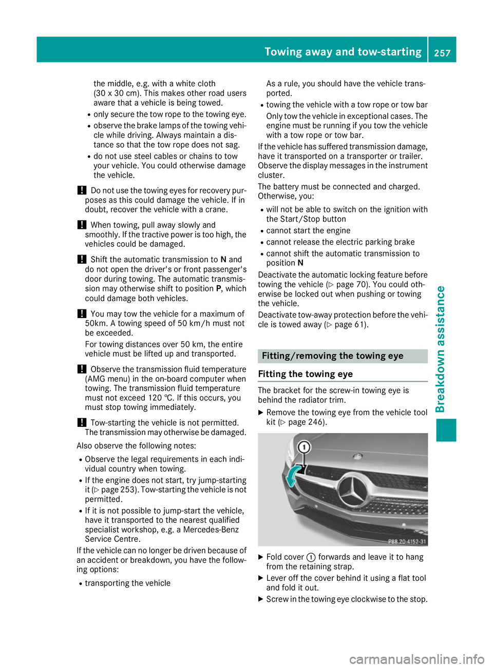
Fitting the towing eye The bracket for the screw-in towing eye is
behind the radiator trim.
X Remove the towing eye from the vehicle tool
kit (Y page 246). X
Fold cover :forwards and leave it to hang
from the retaining strap.
X Lever off the cover behind it using a flat tool
and fold it out.
X Screw in the towing eye clockwise to the stop. Towing away and tow-starting
257Breakdown assistance Z
Page 261 of 289
Removing the towing eye
X
Loosen the towing eye and unscrew it.
X Fold down the inner cover until it engages.
X Attach cover at the bottom and press it in at
the top until it engages.
X Put the towing eye back into the vehicle tool
kit. Towing the vehicle with all wheels on
the ground
It is important that you observe the safety
instructions when towing away your vehicle
(Y page 256).
The automatic transmission automatically shifts to position Pwhen you open the driver's or front-
passenger door or when you remove the key
from the ignition lock. In order to ensure that the automatic transmission stays in position N
when towing away the vehicle, you must
observe the following points:
X Insert the key into the ignition lock. You must
use the key instead of the Start/Stop button
(Y page 103).
X Start the engine and leave it running during
the entire towing procedure.
X Depress the brake pedal and keep it
depressed.
X Move the transmission to position Nwith the
E-SELECT lever.
X Check the transmission position using the
indicator in the multifunction display
(Y page 111).
X Release the brake pedal.
X Release the electric parking brake.
X Switch on the hazard warning lamps
(Y page 90).
In order to signal a change of direction when
towing the vehicle with the hazard warning
lamps switched on, use the combination switch as usual. In this case, only the turn signals for
the desired direction flash. When you reset the
combination switch, the hazard warning lamps
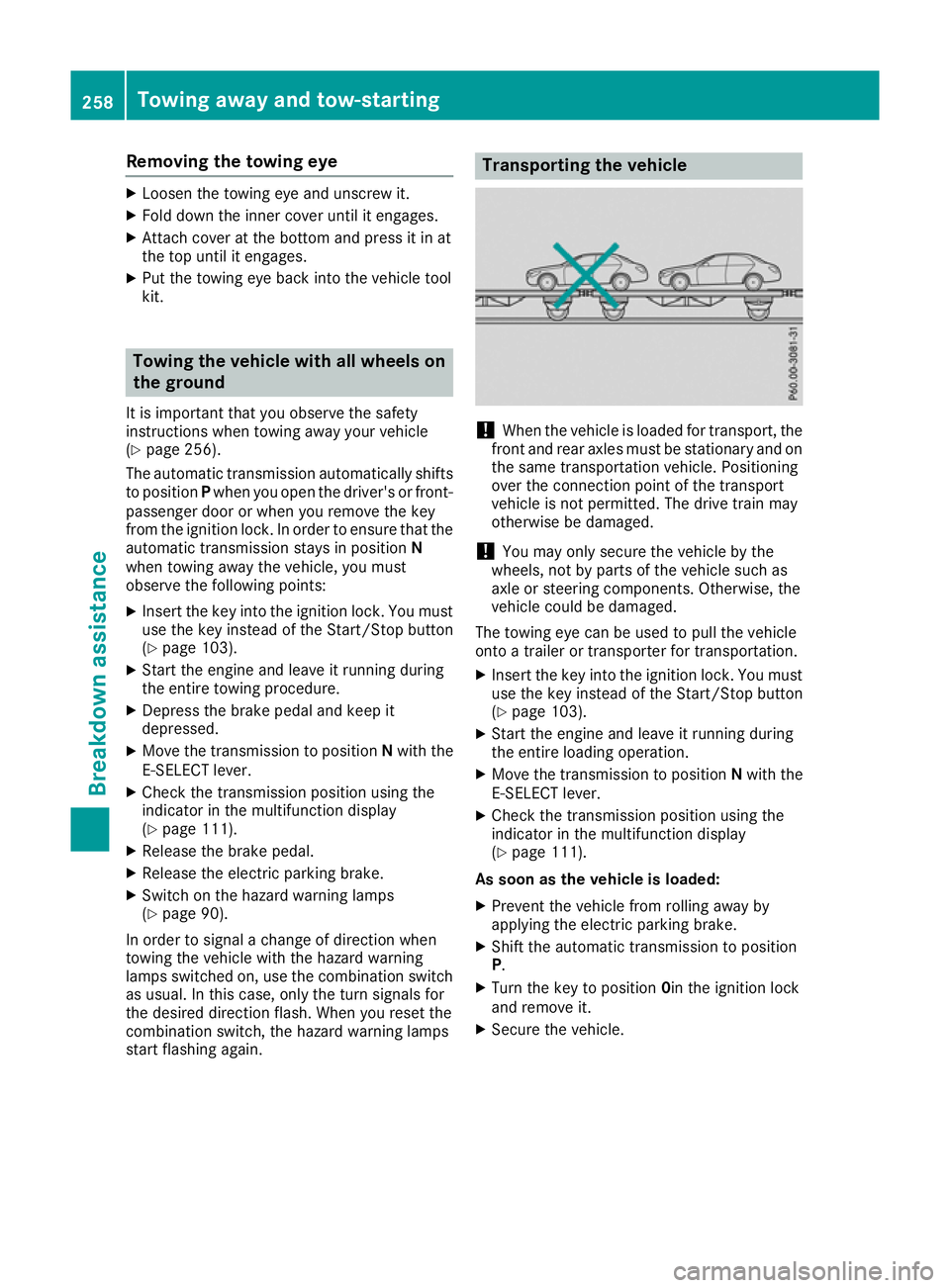
start flashing again. Transporting the vehicle
!
When the vehicle is loaded for transport, the
front and rear axles must be stationary and on the same transportation vehicle. Positioning
over the connection point of the transport
vehicle is not permitted. The drive train may
otherwise be damaged.
! You may only secure the vehicle by the
wheels, not by parts of the vehicle such as
axle or steering components. Otherwise, the
vehicle could be damaged.
The towing eye can be used to pull the vehicle
onto a trailer or transporter for transportation.
X Insert the key into the ignition lock. You must
use the key instead of the Start/Stop button
(Y page 103).
X Start the engine and leave it running during
the entire loading operation.
X Move the transmission to position Nwith the
E-SELECT lever.
X Check the transmission position using the
indicator in the multifunction display
(Y page 111).
As soon as the vehicle is loaded:
X Prevent the vehicle from rolling away by
applying the electric parking brake.
X Shift the automatic transmission to position
P.
X Turn the key to position 0in the ignition lock
and remove it.
X Secure the vehicle. 258
Towing away and tow-startingBreakdown assistance
Page 262 of 289
Tow-starting (emergency engine
starting)
! Do not tow-start vehicles with automatic
transmission. You could otherwise damage
the automatic transmission.
i You can find information on "Jump-starting"
under (Y page 253). Fuses
Important safety notes
G
WARNING
If you manipulate, bridge or replace a faulty
fuse with a fuse of a higher amperage, the
electric cables could be overloaded. This may result in a fire. There is a risk of an accident
and injury.
Always replace faulty fuses with specified new fuses of the correct amperage.
Blown fuses must be replaced with fuses of the same rating, which you can recognise by the
colour and fuse rating. The fuse ratings are listed
in the fuse allocation chart.
The fuse allocation chart is on the fuse box in the luggage compartment (Y page 260).
If the newly inserted fuse also blows, have the
cause traced and rectified at a qualified special-
ist workshop, e.g. a Mercedes-Benz Service
Centre.
! Only use fuses that have been approved for
Mercedes-Benz vehicles and which have the
correct fuse rating for the system concerned.
Otherwise, components or systems could be
damaged.
! Make sure that no moisture can enter the
fuse box when the cover is open.
! When closing the cover, make sure that it is
lying correctly on the fuse box. Moisture seep-
ing in or dirt could otherwise impair the oper- ation of the fuses.
The fuses in your vehicle disconnect faulty cir-
cuits. If a fuse blows, all the components on the circuit and their functions will fail. Before replacing a fuse
X Switch off the engine.
X Switch off all electrical consumers.
X Open the driver's door.
The on-board electronics now have status 0.
This is the same as the key having been
removed.
or, if the key is inserted in the ignition lock: X Remove the key from the ignition lock.
X Safeguard the vehicle against rolling away
(Y page 119).
All indicator lamps in the instrument cluster
must be off. Fuse box in the front-passenger foot-
well
! The floor panel must be fitted properly, oth-
erwise moisture or dirt could impair the func- tion of the fuses. X
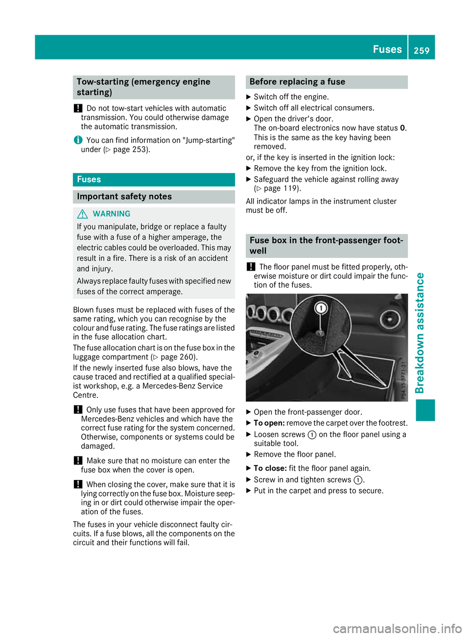
Open the front-passenger door.
X To open: remove the carpet over the footrest.
X Loosen screws :on the floor panel using a
suitable tool.
X Remove the floor panel.
X To close: fit the floor panel again.
X Screw in and tighten screws :.
X Put in the carpet and press to secure. Fuses
259Breakdown assistance Z
Page 265 of 289

Turn on ESP
®
and adapt your driving style
accordingly. When the outside temperature
falls below 10 †, use M+S tyres.
i Different driving styles may lead to higher
levels of tyre wear, meaning the tyres may
wear down to the minimum tyre tread depth
after less mileage. Regular checking of wheels and tyres
G
WARNING
Damaged tyres can cause tyre inflation pres-
sure loss. As a result, you could lose control of your vehicle. There is a risk of accident.
Check the tyres regularly for signs of damageand replace any damaged tyres immediately.
Check wheels and tyres for damage at least
once a month. Check wheels and tyres after
driving off-road or on rough roads. Damaged
wheels can cause a loss of tyre pressure. Pay
particular attention to damage such as:
R cuts in the tyres
R punctures
R tears in the tyres
R bulges on the tyres
R deformation or severe corrosion on wheels
Regularly check the tyre tread depth and the
condition of the tread across the whole width of
the tyre (Y page 262). If necessary, turn the
front wheels to full lock in order to inspect the
inner side of the tyre surface.
All wheels must have a valve cap to protect the
valve against dirt and moisture. Do not fit any-
thing onto the valve other than the standard
valve cap or other valve caps approved for your vehicle by Mercedes-Benz. Do not fit any other
valve caps or systems, e.g. tyre pressure moni-
toring systems.
Regularly check the pressure of all the tyres,
particularly prior to long trips. Adjust the tyre
pressure as necessary (Y page 264).
Observe the notes on the emergency spare
wheel (Y page 273). The service life of tyres depends on various fac-
tors, including the following:
R driving style
R tyre pressure
R mileage Notes on the tyre tread
G
WARNING
Insufficient tyre tread will reduce tyre trac-
tion. The tyre is no longer able to dissipate
water. This means that on wet road surfaces, the risk of aquaplaning increases, in particularwhere speed is not adapted to suit the driving
conditions. There is a risk of accident.
If the tyre pressure is too high or too low, tyres may exhibit different levels of wear at differ-
ent locations on the tyre tread. Thus, you
should regularly check the tread depth and
the condition of the tread across the entire
width of all tyres.
Minimum tyre tread depth for:
R summer tyres: 3 mm
R M+S tyres: 4 mm
For safety reasons, replace the tyres before
the legally prescribed limit for the minimum
tyre tread depth is reached. Selecting, fitting and replacing tyres
G
WARNING
Exceeding the stated tyre load-bearing capa-
city and the approved maximum speed could
lead to tyre damage or the tyre bursting. There is a risk of accident.
Therefore, only use tyre types and sizes
approved for your vehicle model. Observe the
tyre load rating and speed rating required for your vehicle.
Pay special attention to country-specific
requirements for tyre approval. These require-
ments can stipulate a specific tyre type for your
vehicle. Furthermore, the use of certain tyre
types in certain regions and areas of operation
can be highly beneficial. You can find further 262
OperationWheels and tyres
Page 271 of 289
may also be damaged. There is a risk of acci-
dent.
Interchange front and rear wheels only if the
wheels and tyres are of the same dimensions.
! On vehicles fitted with a tyre pressure mon-
itor, electronic components are located in the wheel.
Tyre-fitting tools should not be applied in thearea of the valve, as this could damage the
electronic components.
Only have tyres changed at a qualified spe-
cialist workshop.
Interchanging front and rear wheels of differing
dimensions can render the general operating
permit invalid.
Observe the instructions and safety notes in the "Fitting a wheel" section (Y page 268).
The wear patterns on the front and rear tyres
differ depending on the operating conditions.
Interchange the wheels before a clear wear pat-
tern has formed on the tyres. Front tyres typi-
cally wear more on the shoulders and the rear
tyres in the centre.
On vehicles that have the same size front and
rear wheels, you can interchange the wheels
every 5000 to 10,000 km depending on the
degree of tyre wear. Ensure the direction of
rotation is maintained.
Clean the contact surfaces of the wheel and the brake disc thoroughly every time a wheel is
interchanged. Check the tyre pressure and reac-
tivate the tyre pressure monitor if necessary. Direction of rotation
Tyres with a specified direction of rotation have additional benefits, e.g. if there is a risk of aqua- planing. These advantages can only be gained if
the tyres are fitted corresponding to the direc-
tion of rotation.
An arrow on the sidewall of the tyre indicates its correct direction of rotation. Storing wheels
Store wheels in a cool, dry and preferably dark
place if they are not being used. Protect the
tyres against oil, grease, petrol and diesel. Fitting a wheel
Preparing the vehicle X
Stop the vehicle on solid, non-slippery and
level ground.
X Apply the electric parking brake manually.
X Move the front wheels to the straight-ahead
position.
X Shift the transmission to position P.
X Switch off the engine.
X Pump the tyre to the specified tyre pres-
sure:
open the driver's door.
The on-board electronics now have status 0.
This is the same as the key having been
removed.
or X Remove the key from the ignition lock.
X If included in the vehicle equipment, remove
the tyre-change tool kit from the vehicle.
X Safeguard the vehicle against rolling away.
i Apart from some country-specific variants,
vehicles are not equipped with tyre-changing
tools. Some tools for changing a wheel are
specific to the vehicle. For more information
on which tools are required to perform a
wheel change on your vehicle, consult a quali- fied specialist workshop.
Necessary tyre-changing tools may include,
for example:
R jack
R wheel chock
R wheel wrench
R centring pin
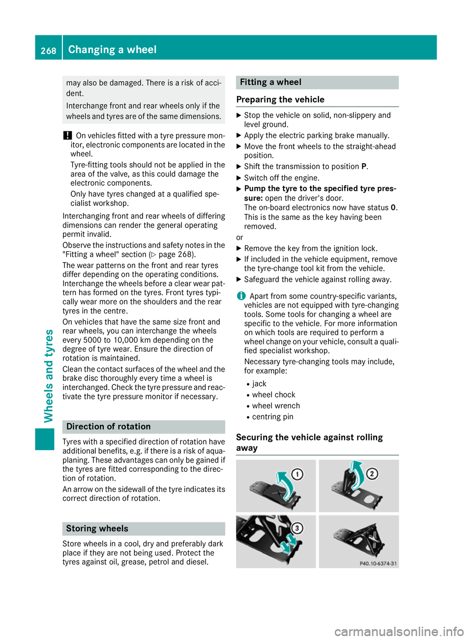
Securing the vehicle against rolling
away 268
Changing a wheelWheels and tyres
Page 272 of 289
If your vehicle is equipped with a wheel chock, it
can be found in the tyre-change tool kit
(Y page 246).
The folding wheel chock is an additional secur-
ing measure to safeguard the vehicle from roll-
ing away, for example when changing a wheel.
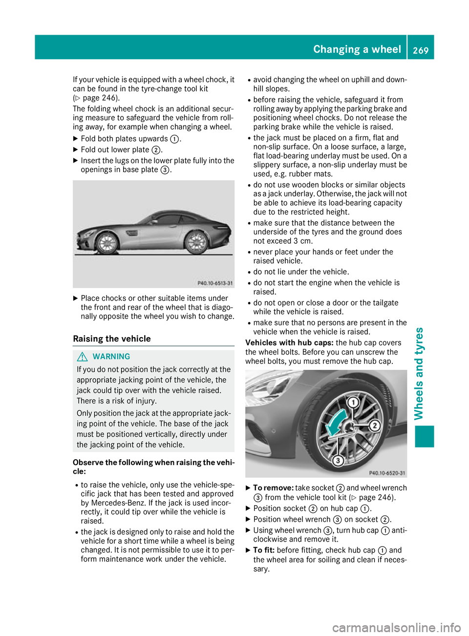
X Fold both plates upwards :.
X Fold out lower plate ;.
X Insert the lugs on the lower plate fully into the
openings in base plate =.X
Place chocks or other suitable items under
the front and rear of the wheel that is diago-
nally opposite the wheel you wish to change.
Raising the vehicle G
WARNING
If you do not position the jack correctly at the appropriate jacking point of the vehicle, the
jack could tip over with the vehicle raised.
There is a risk of injury.
Only position the jack at the appropriate jack-
ing point of the vehicle. The base of the jack
must be positioned vertically, directly under
the jacking point of the vehicle.
Observe the following when raising the vehi- cle:
R to raise the vehicle, only use the vehicle-spe-
cific jack that has been tested and approved
by Mercedes-Benz. If the jack is used incor-
rectly, it could tip over while the vehicle is
raised.
R the jack is designed only to raise and hold the
vehicle for a short time while a wheel is being
changed. It is not permissible to use it to per- form maintenance work under the vehicle. R
avoid changing the wheel on uphill and down-
hill slopes.
R before raising the vehicle, safeguard it from
rolling away by applying the parking brake and
positioning wheel chocks. Do not release theparking brake while the vehicle is raised.
R the jack must be placed on a firm, flat and
non-slip surface. On a loose surface, a large,
flat load-bearing underlay must be used. On a
slippery surface, a non-slip underlay must be
used, e.g. rubber mats.
R do not use wooden blocks or similar objects
as a jack underlay. Otherwise, the jack will not
be able to achieve its load-bearing capacity
due to the restricted height.
R make sure that the distance between the
underside of the tyres and the ground does
not exceed 3 cm.
R never place your hands or feet under the
raised vehicle.
R do not lie under the vehicle.
R do not start the engine when the vehicle is
raised.
R do not open or close a door or the tailgate
while the vehicle is raised.
R make sure that no persons are present in the
vehicle when the vehicle is raised.
Vehicles with hub caps: the hub cap covers
the wheel bolts. Before you can unscrew the
wheel bolts, you must remove the hub cap. X
To remove: take socket;and wheel wrench
= from the vehicle tool kit (Y page 246).
X Position socket ;on hub cap :.
X Position wheel wrench =on socket ;.
X Using wheel wrench =, turn hub cap:anti-
clockwise and remove it.
X To fit: before fitting, check hub cap :and
the wheel area for soiling and clean if neces-
sary. Changing a wheel
269Wheels and tyres Z