Page 418 of 524

Maintenance
44
7
Pneumatic tire: A mechanical
device made of rubber, chemicals,
fabric and steel or other materials,
that, when mounted on an automo-
tive wheel, provides the traction and
contains the gas or fluid that sustains
the load.
Production options weight: The
combined weight of installed regular
production options weighing over 5
lb.(2.3 kg) in excess of the standard
items which they replace, not previ-
ously considered in curb weight or
accessory weight, including heavy
duty brakes, ride levelers, roof rack,
heavy duty battery, and special trim.
Recommended Inflation Pressure :
Vehicle manufacturer's recommend-
ed tire inflation pressure and shown
on the tire placard.
Radial Ply Tire : A pneumatic tire in
which the ply cords that extend to the
beads are laid at 90 degrees to the
centerline of the tread.
Rim: A metal support for a tire and
upon which the tire beads are seated. Sidewall: The portion of a tire
between the tread and the bead.
Speed Rating: An alphanumeric
code assigned to a tire indicating the
maximum speed at which a tire can
operate.
Traction: The friction between the
tire and the road surface. The
amount of grip provided.
Tread: The portion of a tire that
comes into contact with the road.
Treadwear Indicators: Narrow
bands, sometimes called "wear
bars," that show across the tread of a
tire when only 2/32 inch of tread
remains.
UTQGS: Uniform Tire Quality
Grading Standards, a tire information
system that provides consumers with
ratings for a tire's traction, tempera-
ture and treadwear. Ratings are
determined by tire manufacturers
using government testing proce-
dures. The ratings are molded into
the sidewall of the tire.
Vehicle Capacity Weight
: The num-
ber of designated seating positions
multiplied by 68 kg (150 lbs.) plus the
rated cargo and luggage load.
Vehicle Maximum Load on the
Tire: Load on an individual tire due to
curb and accessory weight plus
maximum occupant and cargo
weight.
Vehicle Normal Load on the Tire :
Load on an individual tire that is
determined by distributing to each
axle its share of the curb weight,
accessory weight, and normal occu-
pant weight and driving by 2.
Vehicle Placard: A label permanent-
ly attached to a vehicle showing the
original equipment tire size and rec-
ommended inflation pressure.
Page 421 of 524

747
Maintenance
FUSES
A vehicle’s electrical system is pro-
tected from electrical overload dam-
age by fuses.
This vehicle has 3 (or 4) fuse panels,
one located in the driver’s side panel
bolster, the other in the motor com-
partment near the battery.
If any of your vehicle’s lights, acces-
sories, or controls do not work, check
the appropriate circuit fuse. If a fuse
has blown, the element inside the
fuse will melt.
If the electrical system does not
work, first check the driver’s side
fuse panel.
Always replace a blown fuse with
one of the same rating.
If the replacement fuse blows, this
indicates an electrical problem. Avoid
using the system involved and imme-
diately consult an authorized Kia
dealer.
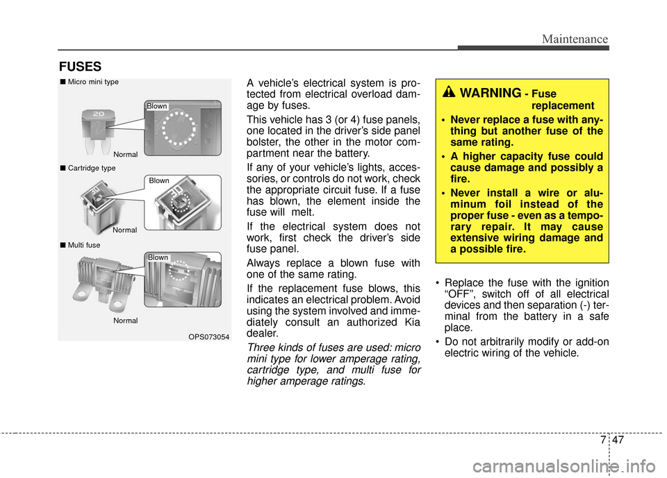
Three kinds of fuses are used: micromini type for lower amperage rating,cartridge type, and multi fuse forhigher amperage ratings.
Replace the fuse with the ignition “OFF”, switch off of all electrical
devices and then separation (-) ter-
minal from the battery in a safe
place.
Do not arbitrarily modify or add-on electric wiring of the vehicle.
WARNING- Fuse
replacement
Never replace a fuse with any- thing but another fuse of the
same rating.
A higher capacity fuse could cause damage and possibly a
fire.
Never install a wire or alu- minum foil instead of the
proper fuse - even as a tempo-
rary repair. It may cause
extensive wiring damage and
a possible fire.
OPS073054
Normal
Normal
■
Micro mini type
■ Cartridge type
■ Multi fuse
Blown
Blown
Normal
Blown
Page 424 of 524
Maintenance
50
7
Fuse switch
Always, put the fuse switch at the ON
position.
If you move the switch to the OFF
position, some items such as audio
and digital clock must be reset and
transmitter (or smart key) may not
work properly.
✽ ✽
NOTICE
If you need to park your vehicle for
prolonged periods more than 1
month, move the transportation fuse
switch to the OFF position to pre-
vent the battery being discharged.
Motor compartment fuse
replacement
1. Turn the ignition switch and all
other switches off.
2. Remove the fuse panel cover by pressing the tab and pulling the
cover up.
3. Check the removed fuse; replace it if it is blown. To remove or insert
the fuse, use the fuse puller in the
motor compartment fuse panel.
4. Push in a new fuse of the same rating, and make sure it fits tightly
in the clips. If it fits loosely, consult
an authorized Kia dealer.
OPSE074009
OPSE075008N
Page 425 of 524
751
Maintenance
Multi fuse
If the multi fuse is blown, it must be
removed as follows:
1. Turn off the vehicle.
2. Disconnect the negative batterycable.
3. Remove the nuts shown in the pic- ture above.
4. Replace the fuse with a new one of the same rating.
5. Reinstall in the reverse order of removal.
✽ ✽NOTICE
If the multi fuse is blown, consult an
authorized Kia dealer.CAUTION- Fuse panel
covers
After checking the fuse panel inthe motor compartment, secure-ly install the fuse panel coverwith using cover locking sound.If not, electrical failures mayoccur from water contact.
OPSE074033
Page 431 of 524
757
Maintenance
Fuse Name Fuse ratingCircuit Protected
IG1 40A Button Start (ACC) Relay, Button Start (IG1) Relay
BLOWER 40A Blower Relay IG3 1 30A IG3 #1/#2/#3/#4/#5 Relay
EPB 1 30A Electronic Parking Brake Module
EPB 2 30A Electronic Parking Brake Module
IG3 2 10A Blower Relay, A/C Control Module, A/C Compressor, E/R Junction Block (Cooling Fan 1/2 Relay), Heater
Assembly (PTC Heater)
CHARGER 1 10A OBC Unit, BMS Control Module EWP 10A Electronic Water Pump
IG3 3 15A EPCU, Transaxle Range Switch, A/V & Navigation Head Unit, Instrument Cluster
HORN 15A Horn Relay
B/UP LAMP 10A Transaxle Range Switch, EPCU
BATTERY C/FAN 25A Battery C/FAN Relay
No. Relay Name Type
E41 Power Outlet Relay PLUG MICRO
E42 C/FAN 1 Relay PLUG MICRO
E43 RR HTD Relay PLUG MICRO
E44 C/FAN 2 Relay PLUG MINI
Page 432 of 524
Maintenance
58
7
Motor compartment fuse panel
(Battery terminal cover)
✽ ✽ NOTICE
The actual fuse/relay panel label
may differ depending on equip-
ment/options.
OPSE074015L
OPSE074014
Page 435 of 524
761
Maintenance
1. Turn off the vehicle and open thehood.
2. Disconnect the power connector from the back of the headlight
assembly.
3. Disconnect the negative batterycable.
4. Loosen the retaining bolts. 5. Pull out the end of the front
bumper.
If you can reach the bulb without
removing the headlight assembly,
you do not need to do step 4,5 and 6.
6. Remove the headlight assembly from the body of the vehicle.
OPSE074018
OPSE074019
Page 459 of 524

Index
2I
Active ECO system. . . . . . . . . . . . . . . . . . . . . . . . . . . . 5-10Active ECO operation . . . . . . . . . . . . . . . . . . . . . . . 5-10
Air bag - advanced supplemental restraint system . . . . 3-34 Adding equipment to or modifying your airbag-equipped vehicle . . . . . . . . . . . . . . . . . . . . . . . 3-57
Air bag warning label. . . . . . . . . . . . . . . . . . . . . . . . 3-57
Air bag warning light . . . . . . . . . . . . . . . . . . . . . . . . 3-37
Curtain air bag . . . . . . . . . . . . . . . . . . . . . . . . . . . . . 3-50
Do not installing a child restraint on a front passenger's seat . . . . . . . . . . . . . . . . . . . . . . . . . . . 3-37
Driver's and passenger's front air bag . . . . . . . . . . . 3-46
How does the air bag system operate . . . . . . . . . . . 3-35
Inflation and non-inflation conditions of the air bag . . 3-51
Occupant Detection System (ODS) . . . . . . . . . . . . . 3-41
Side air bag. . . . . . . . . . . . . . . . . . . . . . . . . . . . . . . . 3-49
SRS Care . . . . . . . . . . . . . . . . . . . . . . . . . . . . . . . . . 3-56
SRS components and functions . . . . . . . . . . . . . . . . 3-38
Air conditioning system . . . . . . . . . . . . . . . . . . . . . . . . . 8-3
Appearance care . . . . . . . . . . . . . . . . . . . . . . . . . . . . . . 7-69 Exterior care . . . . . . . . . . . . . . . . . . . . . . . . . . . . . . . 7-69
Interior care . . . . . . . . . . . . . . . . . . . . . . . . . . . . . . . 7-74
Audio system . . . . . . . . . . . . . . . . . . . . . . . . . . . . . . . 4-126 Antenna . . . . . . . . . . . . . . . . . . . . . . . . . . . . . . . . . 4-126
Audio . . . . . . . . . . . . . . . . . . . . . . . . . . . . . . . . . . . 4-\
140
Audio remote control . . . . . . . . . . . . . . . . . . . . . . . 4-127
Aux, USB and iPod
®port . . . . . . . . . . . . . . . . . . . 4-128 How vehicle audio works . . . . . . . . . . . . . . . . . . . . 4-130
Precautions for Safe Driving . . . . . . . . . . . . . . . . . 4-137
Speaker lights . . . . . . . . . . . . . . . . . . . . . . . . . . . . . 4-129
Using iPod
®device . . . . . . . . . . . . . . . . . . . . . . . . 4-135
Using the USB device . . . . . . . . . . . . . . . . . . . . . . 4-134
Voice Recognition . . . . . . . . . . . . . . . . . . . . . . . . . 4-138
When connecting a Bluetooth
®Phone. . . . . . . . . . 4-137
Auto defogging system . . . . . . . . . . . . . . . . . . . . . . . . 4-114
Automatic climate control system . . . . . . . . . . . . . . . . 4-94 Automatic heating and air conditioning. . . . . . . . . . 4-95
Checking the amount of air conditioner refrigerantand compressor lubricant . . . . . . . . . . . . . . . . . . . 4-109
Climate control air filter. . . . . . . . . . . . . . . . . . . . . 4-108
Manual heating and air conditioning . . . . . . . . . . . . 4-96
System operation . . . . . . . . . . . . . . . . . . . . . . . . . . 4-106
Battery. . . . . . . . . . . . . . . . . . . . . . . . . . . . . . . . . . . . \
. . 7-31 Battery recharging . . . . . . . . . . . . . . . . . . . . . . . . . . 7-32
For best battery service . . . . . . . . . . . . . . . . . . . . . . 7-31
Reset items . . . . . . . . . . . . . . . . . . . . . . . . . . . . . . . . 7-33
Before driving . . . . . . . . . . . . . . . . . . . . . . . . . . . . . . . . . 5-3 Before entering vehicle . . . . . . . . . . . . . . . . . . . . . . . 5-3
Before starting . . . . . . . . . . . . . . . . . . . . . . . . . . . . . . 5-3
Necessary inspections . . . . . . . . . . . . . . . . . . . . . . . . 5-3
Brake fluid . . . . . . . . . . . . . . . . . . . . . . . . . . . . . . . . . . 7-23\
A
B