2016 KIA Soul EV roof
[x] Cancel search: roofPage 381 of 524
77
Maintenance
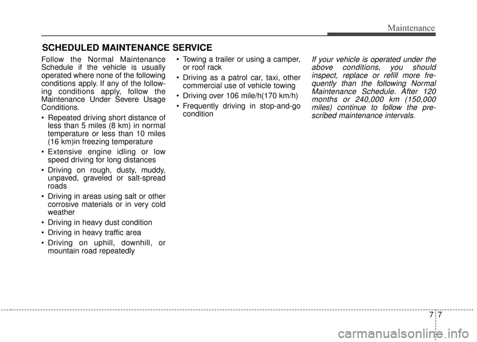
SCHEDULED MAINTENANCE SERVICE
Follow the Normal Maintenance
Schedule if the vehicle is usually
operated where none of the following
conditions apply. If any of the follow-
ing conditions apply, follow the
Maintenance Under Severe Usage
Conditions.
Repeated driving short distance ofless than 5 miles (8 km) in normal
temperature or less than 10 miles
(16 km)in freezing temperature
Extensive engine idling or low speed driving for long distances
Driving on rough, dusty, muddy, unpaved, graveled or salt-spread
roads
Driving in areas using salt or other corrosive materials or in very cold
weather
Driving in heavy dust condition
Driving in heavy traffic area
Driving on uphill, downhill, or mountain road repeatedly Towing a trailer or using a camper,
or roof rack
Driving as a patrol car, taxi, other commercial use of vehicle towing
Driving over 106 mile/h(170 km/h)
Frequently driving in stop-and-go conditionIf your vehicle is operated under theabove conditions, you shouldinspect, replace or refill more fre-quently than the following NormalMaintenance Schedule. After 120months or 240,000 km (150,000miles) continue to follow the pre-scribed maintenance intervals.
Page 392 of 524
Maintenance
18
7
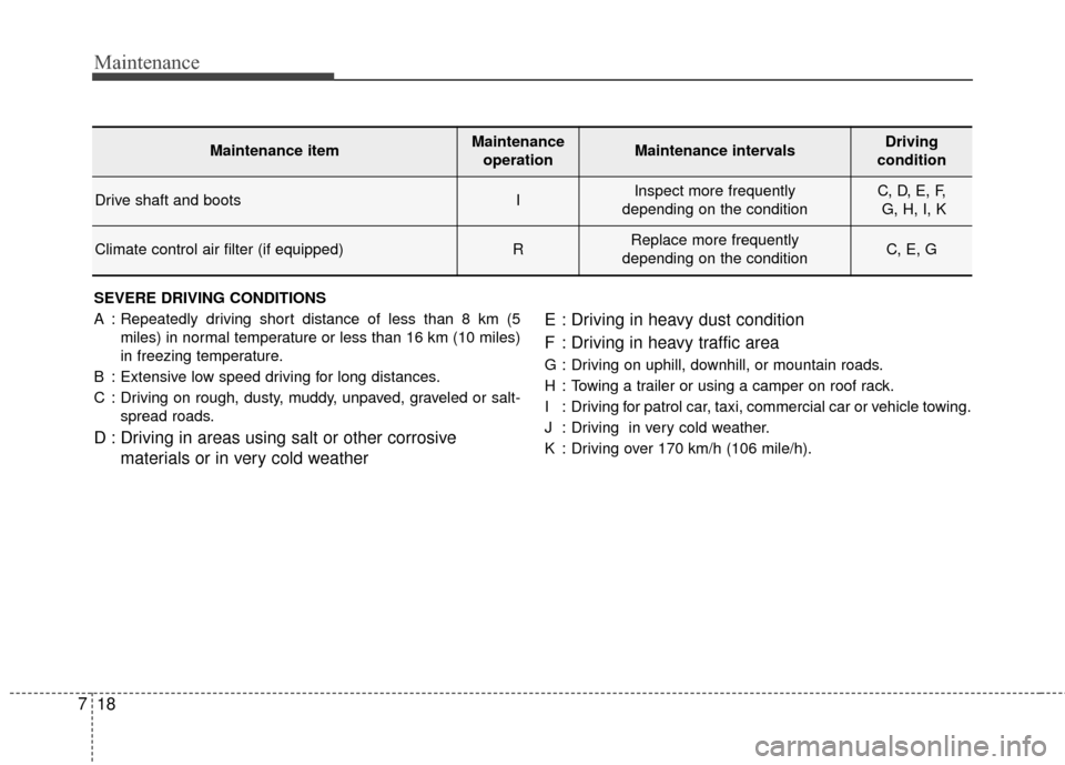
SEVERE DRIVING CONDITIONS
A : Repeatedly driving short distance of less than 8 km (5
miles) in normal temperature or less than 16 km (10 miles)
in freezing temperature.
B : Extensive low speed driving for long distances.
C : Driving on rough, dusty, muddy, unpaved, graveled or salt- spread roads.
D : Driving in areas using salt or other corrosive materials or in very cold weather E : Driving in heavy dust condition
F : Driving in heavy traffic area
G : Driving on uphill, downhill, or mountain roads.
H : Towing a trailer or using a camper on roof rack.
I : Driving for patrol car, taxi, commercial car or vehicle towing.
J : Driving in very cold weather.
K : Driving over 170 km/h (106 mile/h).
Maintenance itemMaintenance
operationMaintenance intervalsDriving
condition
Drive shaft and bootsIInspect more frequently
depending on the conditionC, D, E, F, G, H, I, K
Climate control air filter (if equipped)RReplace more frequently
depending on the conditionC, E, G
Page 418 of 524
Maintenance
44
7
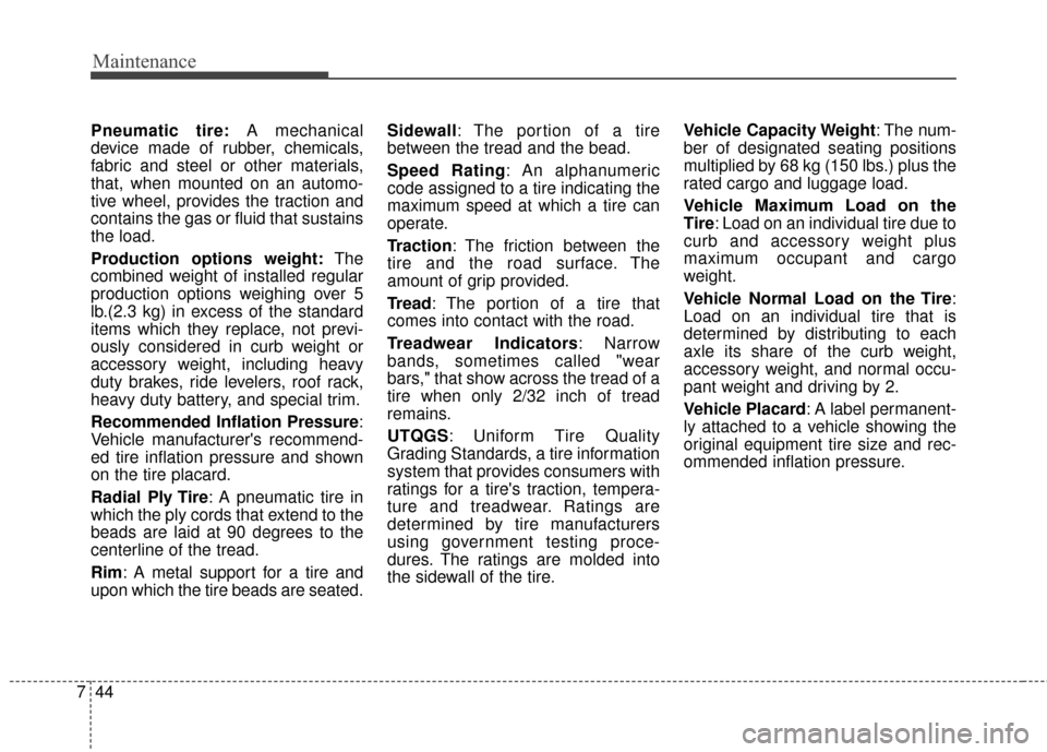
Pneumatic tire: A mechanical
device made of rubber, chemicals,
fabric and steel or other materials,
that, when mounted on an automo-
tive wheel, provides the traction and
contains the gas or fluid that sustains
the load.
Production options weight: The
combined weight of installed regular
production options weighing over 5
lb.(2.3 kg) in excess of the standard
items which they replace, not previ-
ously considered in curb weight or
accessory weight, including heavy
duty brakes, ride levelers, roof rack,
heavy duty battery, and special trim.
Recommended Inflation Pressure :
Vehicle manufacturer's recommend-
ed tire inflation pressure and shown
on the tire placard.
Radial Ply Tire : A pneumatic tire in
which the ply cords that extend to the
beads are laid at 90 degrees to the
centerline of the tread.
Rim: A metal support for a tire and
upon which the tire beads are seated. Sidewall: The portion of a tire
between the tread and the bead.
Speed Rating: An alphanumeric
code assigned to a tire indicating the
maximum speed at which a tire can
operate.
Traction: The friction between the
tire and the road surface. The
amount of grip provided.
Tread: The portion of a tire that
comes into contact with the road.
Treadwear Indicators: Narrow
bands, sometimes called "wear
bars," that show across the tread of a
tire when only 2/32 inch of tread
remains.
UTQGS: Uniform Tire Quality
Grading Standards, a tire information
system that provides consumers with
ratings for a tire's traction, tempera-
ture and treadwear. Ratings are
determined by tire manufacturers
using government testing proce-
dures. The ratings are molded into
the sidewall of the tire.
Vehicle Capacity Weight
: The num-
ber of designated seating positions
multiplied by 68 kg (150 lbs.) plus the
rated cargo and luggage load.
Vehicle Maximum Load on the
Tire: Load on an individual tire due to
curb and accessory weight plus
maximum occupant and cargo
weight.
Vehicle Normal Load on the Tire :
Load on an individual tire that is
determined by distributing to each
axle its share of the curb weight,
accessory weight, and normal occu-
pant weight and driving by 2.
Vehicle Placard: A label permanent-
ly attached to a vehicle showing the
original equipment tire size and rec-
ommended inflation pressure.
Page 428 of 524
Maintenance
54
7
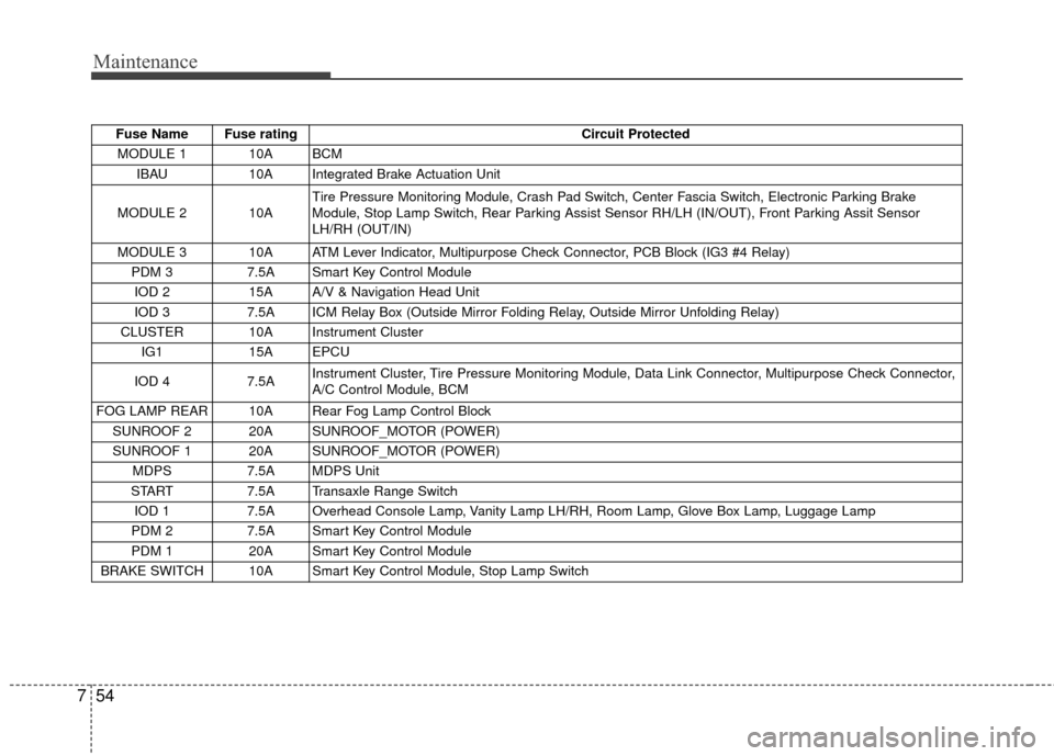
Fuse Name Fuse rating Circuit Protected
MODULE 1 10A BCM IBAU 10A Integrated Brake Actuation Unit
MODULE 2 10A Tire Pressure Monitoring Module, Crash Pad Switch, Center Fascia Switch, Electronic Parking Brake
Module, Stop Lamp Switch, Rear Parking Assist Sensor RH/LH (IN/OUT), Front Parking Assit Sensor
LH/RH (OUT/IN)
MODULE 3 10A ATM Lever Indicator, Multipurpose Check Connector, PCB Block (IG3 #4 Relay) PDM 3 7.5A Smart Key Control Module
IOD 2 15A A/V & Navigation Head Unit
IOD 3 7.5A ICM Relay Box (Outside Mirror Folding Relay, Outside Mirror Unfolding Relay)
CLUSTER 10A Instrument Cluster IG1 15A EPCU
IOD 4 7.5A Instrument Cluster, Tire Pressure Monitoring Module, Data Link Connector, Multipurpose Check Connector,
A/C Control Module, BCM
FOG LAMP REAR 10A Rear Fog Lamp Control Block SUNROOF 2 20A SUNROOF_MOTOR (POWER)
SUNROOF 1 20A SUNROOF_MOTOR (POWER) MDPS 7.5A MDPS Unit
START 7.5A Transaxle Range Switch
IOD 1 7.5A Overhead Console Lamp, Vanity Lamp LH/RH, Room Lamp, Glove Box Lamp, Luggage Lamp
PDM 2 7.5A Smart Key Control Module
PDM 1 20A Smart Key Control Module
BRAKE SWITCH 10A Smart Key Control Module, Stop Lamp Switch
Page 462 of 524
I5
Index
LCD Display . . . . . . . . . . . . . . . . . . . . . . . . . . . . . . . . . 4-46A/V Mode. . . . . . . . . . . . . . . . . . . . . . . . . . . . . . . . . 4-48
EV information mode. . . . . . . . . . . . . . . . . . . . . . . . 4-47
LCD Modes . . . . . . . . . . . . . . . . . . . . . . . . . . . . . . . 4-46
Service Mode . . . . . . . . . . . . . . . . . . . . . . . . . . . . . . 4-48
User Settings Mode . . . . . . . . . . . . . . . . . . . . . . . . . 4-49
Warning Messages . . . . . . . . . . . . . . . . . . . . . . . . . . 4-51
Light bulbs . . . . . . . . . . . . . . . . . . . . . . . . . . . . . . . . . . 7-59\
Front light replacement . . . . . . . . . . . . . . . . . . . . . . 7-59
High mounted stop light bulb replacement . . . . . . . 7-66
Interior light bulb replacement. . . . . . . . . . . . . . . . . 7-68
License plate light bulb replacement . . . . . . . . . . . . 7-67
Rear combination light bulb replacement . . . . . . . . 7-64
Side repeater light bulb replacement . . . . . . . . . . . . 7-64
Lighting. . . . . . . . . . . . . . . . . . . . . . . . . . . . . . . . . . . . \
. 4-81 Abnormal lamp operation . . . . . . . . . . . . . . . . . . . . 4-82
Abnormal lamp operation due to stabilization ofelectric control system . . . . . . . . . . . . . . . . . . . . . . 4-82
Battery saver function . . . . . . . . . . . . . . . . . . . . . . . 4-81
Daytime running light . . . . . . . . . . . . . . . . . . . . . . . 4-81
Front fog light . . . . . . . . . . . . . . . . . . . . . . . . . . . . . 4-86
Headlamp escort . . . . . . . . . . . . . . . . . . . . . . . . . . . . 4-81
High beam operation . . . . . . . . . . . . . . . . . . . . . . . . 4-84
Lighting control . . . . . . . . . . . . . . . . . . . . . . . . . . . . 4-82
Turn signals and lane change signals . . . . . . . . . . . . 4-85
Luggage volume . . . . . . . . . . . . . . . . . . . . . . . . . . . . . . . 8-3 Maintenance services . . . . . . . . . . . . . . . . . . . . . . . . . . . 7-3
Owner maintenance precautions . . . . . . . . . . . . . . . . 7-4
Owner’s responsibility . . . . . . . . . . . . . . . . . . . . . . . . 7-3
Mirrors . . . . . . . . . . . . . . . . . . . . . . . . . . . . . . . . . . . . \
. 4-35 Inside rearview mirror . . . . . . . . . . . . . . . . . . . . . . . 4-35
Outside rearview mirror . . . . . . . . . . . . . . . . . . . . . . 4-36
Motor number . . . . . . . . . . . . . . . . . . . . . . . . . . . . . . . . . 8-8
Motor room compartment. . . . . . . . . . . . . . . . . . . . . . . . 2-6
Owner maintenance . . . . . . . . . . . . . . . . . . . . . . . . . . . . 7-5 Owner maintenance schedule. . . . . . . . . . . . . . . . . . . 7-6
Panoramic sunroof . . . . . . . . . . . . . . . . . . . . . . . . . . . . 4-24 Resetting the sunroof . . . . . . . . . . . . . . . . . . . . . . . . . . . . 4-28
Sliding the sunroof . . . . . . . . . . . . . . . . . . . . . . . . . . 4-25
Sunroof open warning . . . . . . . . . . . . . . . . . . . . . . . 4-25
Sunshade. . . . . . . . . . . . . . . . . . . . . . . . . . . . . . . . . . 4-27\
Tilting the sunroof . . . . . . . . . . . . . . . . . . . . . . . . . . 4-26
Parking assist system . . . . . . . . . . . . . . . . . . . . . . . . . . 4-76 Non-operational conditions of parking assist system . . 4-77
Operation of the parking assist system . . . . . . . . . . 4-76
Self-diagnosis . . . . . . . . . . . . . . . . . . . . . . . . . . . . . . 4-78
M
O
P
L
Page 484 of 524
19
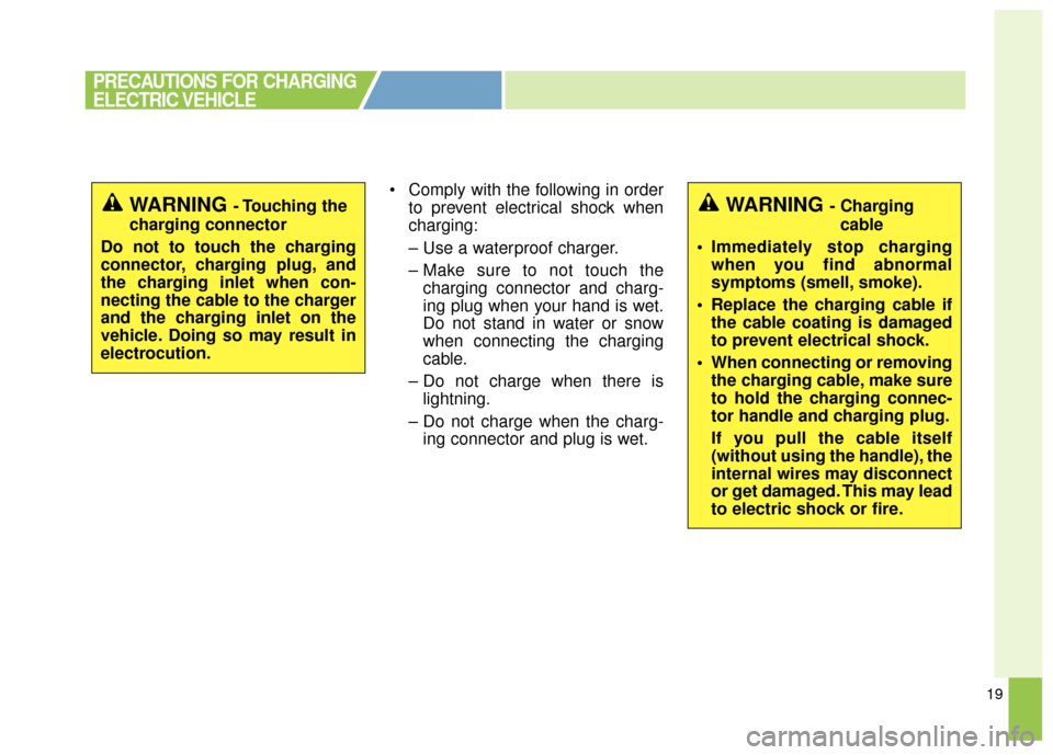
Comply with the following in orderto prevent electrical shock when
charging:
– Use a waterproof charger.
– Make sure to not touch thecharging connector and charg-
ing plug when your hand is wet.
Do not stand in water or snow
when connecting the charging
cable.
– Do not charge when there is lightning.
– Do not charge when the charg- ing connector and plug is wet.
PRECAUTIONS FOR CHARGING
ELECTRIC VEHICLE
WARNING - Touching the
charging connector
Do not to touch the charging
connector, charging plug, and
the charging inlet when con-
necting the cable to the charger
and the charging inlet on the
vehicle. Doing so may result in
electrocution.WARNING - Charging cable
Immediately stop charging when you find abnormal
symptoms (smell, smoke).
Replace the charging cable if the cable coating is damaged
to prevent electrical shock.
When connecting or removing the charging cable, make sure
to hold the charging connec-
tor handle and charging plug.
If you pull the cable itself
(without using the handle), the
internal wires may disconnect
or get damaged. This may lead
to electric shock or fire.
Page 523 of 524
58
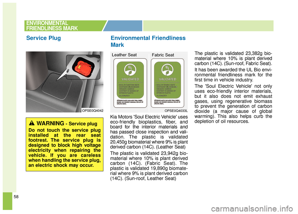
Kia Motors 'Soul Electric Vehicle' uses
eco-friendly bioplastics, fiber, and
board for the interior materials and
has passed close inspection and vali-
dation. The plastic is validated
20,450g biomaterial where 9% is plant
derived carbon (14C). (Leather Seat)
The plastic is validated 23,942g bio-
material where 10% is plant derived
carbon (14C). (Fabric Seat). The
plastic is validated 19,890g biomate-
rial where 9% is plant derived carbon
(14C). (Sun-roof, Leather Seat)The plastic is validated 23,382g bio-
material where 10% is plant derived
carbon (14C). (Sun-roof, Fabric Seat).
It has been awarded the UL Bio envi-
ronmental friendliness mark for the
first time in vehicle industry.
The 'Soul Electric Vehicle' not only
uses eco-friendly interior materials,
but it also does not emit exhaust
gases, using regenerative biomass
to prevent the generation of carbon
dioxide (a major cause of global
warming). This also helps curb the
depletion of oil resources.
Environmental Friendliness
Mark
Service Plug
OPSE0Q4042OPSE0Q4033L
Leather Seat
Fabric Seat
ENVIRONMENTAL
FRIENDLINESS MARK
WARNING- Service plug
Do not touch the service plug
installed at the rear seat
footrest. The service plug is
designed to block high voltage
electricity when repairing the
vehicle. If you are careless
when handling the service plug,
an electric shock may occur.